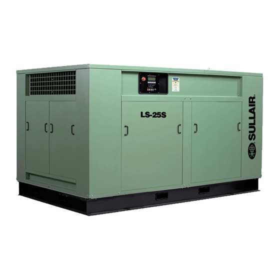
Summarization of Contents
Structure of the Compressor
Overview
General description of the stationary screw compressor unit and its main components.
Air Intake System
Details the air intake process, air filter, and butterfly valve functions.
Air Discharge System
Covers the discharge process, minimum pressure valve, safety valve, and after-cooler.
Lubrication System
Explains the oil circuit, thermostatic valve, oil cooler, and oil filter.
Oil-Gas Separator
Describes the function, structure, and filter element replacement for the oil-gas separator.
Water Circuit System
Details the water circuit, after-cooler, oil cooler, and auto drain valve.
Capacity Control System
Explains how the system automatically adjusts the compressor's air intake based on demand.
Supervisor II Monitor
Covers the functions, display, and buttons of the Supervisor II control monitor.
Installation of the Compressor
Foundation
Requirements for a stable and level base to prevent noise leakage.
Vibration and Noise Reduction
Recommendations for using rubber pads to reduce vibration and noise.
Ventilation and Cooling
Importance of good ventilation for normal operation and temperature control.
Unit Outline and Installation Drawings
Refers to various diagrams for different compressor models.
Installation of Air-Cooled Units
Guidance on connecting separate components of air-cooled units.
Motor Rotation Direction
Procedure to check and correct the motor's rotation direction.
Operation of the Compressor
Safety Operation Regulations
Essential safety guidelines for personnel and machine protection.
Preparation Work Before Initial Startup
Steps to follow before the first start, including parameter setting and checks.
Normal Operation
How to start the compressor for routine operation after initial setup.
Shutdown
Instructions on how to properly shut down the compressor.
Maintenance and Service
Overview
General statement on the low maintenance requirements and monitoring system.
Daily Maintenance
Checks to perform before and after starting the unit for daily operation.
Maintenance After 50 Hours of Operation
Specific maintenance tasks to be performed after the initial 50 operating hours.
Maintenance After 1000 Hours of Operation
Scheduled maintenance for every 1000 operating hours.
Lubricating Oil Change
Guidelines for when and how to change the lubricating oil.
Oil Filter Maintenance
Procedure for maintaining and replacing the oil filter element.
Air Filter Maintenance
How to clean or replace the air filter elements.
Oil-Gas Separator Maintenance
Primarily focuses on replacing the oil-gas separator core.
Shut-off Valve Maintenance
Maintenance procedure for the shut-off valve, mainly O-ring replacement.
Pressure Regulator Maintenance
Maintenance for the pressure regulator, typically replacing seals and diaphragms.
Minimum Pressure Valve Maintenance
Maintenance for the minimum pressure valve, focusing on O-ring replacement.
Blowdown Valve Maintenance
Procedure for maintaining the blowdown valve, mainly O-ring replacement.
Control Line Filter Maintenance
Maintenance of control line filters, including replacing elements and seals.
Electromagnetic Valve Maintenance
Guidance on cleaning and maintaining electromagnetic valves.
Coupling Installation and Maintenance
How to install and maintain the flexible coupling.
Maintenance Instructions for Sullair Compressor Dedicated Motor
Maintenance guidelines for the dedicated motors used with Sullair compressors.
Electrical Schematic Diagram
Water-Cooled Unit Electrical Schematic Diagram
Electrical diagram specific to water-cooled compressor units.
Air-Cooled Unit Electrical Schematic Diagram
Electrical diagram specific to air-cooled compressor units.
High Voltage Unit (Water-Cooled and Air-Cooled) Electrical Schematic Diagram
Electrical diagram for high voltage units, covering both water and air-cooled types.
Fault Analysis and Troubleshooting
Overview
General advice on analyzing and troubleshooting compressor faults.
Possible Compressor Faults and Troubleshooting Methods
A table detailing common symptoms, causes, and solutions for compressor issues.
Sensor Usage and Monitor Parameter Calibration
Instructions on how to use sensors and calibrate monitor parameters.
Spare Parts List
List of Spare Parts Required for Compressor Component Maintenance
A comprehensive list of spare parts for compressor maintenance.


Need help?
Do you have a question about the LS25S-350 and is the answer not in the manual?
Questions and answers