
Related Manuals for Sullair LS-25S-257KW


Summary of Contents for Sullair LS-25S-257KW
- Page 1 INDUSTRIAL ROTARY SCREW AIR COMPRESSOR LS---25S---257KW SUPERVISOR II EQUIPMENT NO. 1---MC---QB001 0---MC---QB001 2---MC---QB001 OPERATOR’S MANUAL AND PARTS LIST Part Number 02250127---759 eSullair Corporation...
- Page 2 AIR CARE SEMINAR TRAINING Sullair Air Care Seminars are 3--day courses that provide hands--on instruction in the proper operation, maintenance and service of Sullair equipment. Individual seminars on Industrial compressors and compressor electrical systems are presented at regular intervals throughout the year at a dedicated training facility at Sullair’s corporate headquarters in Michigan City, Indiana.
-
Page 3: Table Of Contents
1.8 ELECTRICAL SHOCK 1.9 LIFTING 1.10 ENTRAPMENT Section 2 DESCRIPTION 2.1 INTRODUCTION 2.2 DESCRIPTION OF COMPONENTS 2.3 SULLAIR COMPRESSOR UNIT, FUNCTIONAL DESCRIPTION 2.4 COMPRESSOR COOLING AND LUBRICATION SYSTEM, FUNCTIONAL DESCRIPTION 2.5 COMPRESSOR DISCHARGE SYSTEM, FUNCTIONAL DESCRIPTION 2.6 CONTROL SYSTEM, FUNCTIONAL DESCRIPTION 2.7 AIR INLET SYSTEM, FUNCTIONAL DESCRIPTION... - Page 4 TABLE OF CONTENTS (CONTINUED) Section 4 PAGE INSTALLATION (CONT) 4.7 ELECTRICAL PREPARATION 4.8 MOTOR ROTATION CHECK Section 5 OPERATION 5.1 GENERAL 5.2 PURPOSE OF CONTROLS 5.3 PARAMETER SETUP 5.4 OPERATING THE COMPRESSOR 5.5 SUPERVISOR OUTPUT RELAYS 5.6 INITIAL START---UP PROCEDURE 5.7 SUBSEQUENT START---UP PROCEDURE 5.8 SHUTDOWN PROCEDURE Section 6...
- Page 5 TABLE OF CONTENTS (CONTINUED) Section 7 PAGE ILLUSTRATIONS AND PARTS LIST 7.4 COMPRESSOR AIR INTAKE SYSTEM (CONT) 7.5 FLUID COOLING PIPING SYSTEM --- AIR---COOLED REMOTE COOLER 7.6 FLUID COOLING SYSTEM --- AIR---COOLED REMOTE COOLER 7.7 FLUID COOLING SYSTEM --- AIR---COOLED REMOTE (LOW NOISE) 7.8 COMPRESSOR DISCHARGE SYSTEM 7.9 SULLICON CONTROL...
- Page 6 SAFETY 1.1 GENERAL of hose failure, per all applicable Federal, State and Sullair Corporation and its subsidiaries design and Local codes, standards and regulations. manufacture all of their products so they can be op- erated safely. However, the responsibility for safe B.
- Page 7 Section 1 SAFETY 1.4 FIRE AND EXPLOSION K. DO NOT attempt to operate the compressor in any classification of hazardous environment unless the compressor has been specially designed and WA R N I N G manufactured for that duty. 1.5 MOVING PARTS When installing a Base Load Transfer (BLT) Sys- A.
- Page 8 Section 1 SAFETY C. Operate the compressor only in open or ade- E. Disconnect, lock out, and tag all power at source quately ventilated areas. prior to attempting repairs or adjustments to rotating machinery and prior to handling any ungrounded D.
-
Page 9: Entrapment
Section 1 SAFETY O. DO NOT use the lifting eye bolt on the compres- before doing so, or else secure and tag the access sor motor, if supplied, to lift the entire compressor door in the open position to avoid the possibility of package. -
Page 10: Introduction
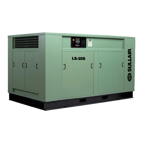
The bricated---type compressor. This unit provides con- complete package includes compressor, electric tinuous pulse---free air compression to meet your Figure 2 ---1 Sullair Series LS ---25S Rotary Screw Compressor... - Page 11 Section 2 DESCRIPTION Figure 2 ---2 Compressor Piping and Instrument Diagram...
-
Page 12: Compressor Cooling And Lubrication System, Functional Description
Section 2 DESCRIPTION needs. With a Sullair compressor, there is no The fluid stop valve prevents fluid from filling the maintenance or inspection of the internal parts of compressor unit when the compressor is shut the compressor unit permitted in accordance with down. -
Page 13: Control System, Functional Description
Section 2 DESCRIPTION The compressor is also equipped with high pres- con Control inactive. Both the spiral valve, as well sure shutdown protection to shut down the com- as the inlet butterfly valve, remain in the full load po- pressor at 135 psig (9.3 bar). This prevents the re- sition as long as the compressor is running at 100 lief valve from opening and dumping fluid under psig (6.9 bar) or below. - Page 14 Section 2 DESCRIPTION Figure 2 ---3A Control System Diagram (Start/ Full Load)
- Page 15 Section 2 DESCRIPTION Figure 2 ---3B Control System Diagram (Modulation/ Unload)
-
Page 16: Air Inlet System, Functional Description
Section 2 DESCRIPTION Figure 2 ---4 Air Inlet System vented through the solenoid valve exhaust port. S ec tion 2 . 6 , Contr ol S y stem, Func tional D esc r ip - The blowdown valve closes, and the inlet butterfly tion) . - Page 17 Section 2 DESCRIPTION Figure 2 ---5 Supervisor II Panel S Continuous --- Starts machine if no alarm Logo --- Used for various functions de- conditions are present. Also used to clear scribed in later sections alarm conditions while machine is running. S Program --- Used to enter the parameter change mode where control parameters S Auto --- Starts machine and selects auto...
-
Page 18: Status Displays
Section 2 DESCRIPTION eter setup mode to increment a value. displays press the up arrow or down arrow keys. When in the default display the key will light Up arrow moves to the next display, down arrow all the lamps for three seconds. the previous display. -
Page 19: Lamp Indicators
Section 2 DESCRIPTION P4 --- (Pressure before oil filter) running. ΔP1 --- (Separate differential pressure) If lit steady, HRS RUN signifies that ΔP1 is being displayed, if flashing de- 001234.0 notes replacement of separator is needed. S Total hours that the compressor has been ΔP2 --- (Oil filter differential pressure) loaded. -
Page 20: A Identification
Section 3 SPECIFICATIONS 3.1A Identification --- LS25S 02250122---158R2... - Page 21 Section 3 SPECIFICATIONS 3.1B Identification --- LS25S Cooler Pack 02250122---154R1...
-
Page 22: Lubrication Guide
3.3 APPLICATION GUIDE particulate level, corrosive gases or strong oxidiz- Sullair encourages the user to participate in a fluid ing gases are present in the air. analysis program with the fluid suppliers. This... - Page 23 NOTES...
-
Page 24: Mounting Of Compressor
Consult a Sullair fluid cooler is not part of the standard scope of sup- office for assistance in utilizing this heat. -
Page 25: Coupling Alignment Check
However, due to shipping and handling, etc. Sullair provides a wiring diagram for use by the it is necessary to recheck the coupling alignment. installer. Refer to Coupling Alignment procedure explained in the Maintenance section of this manual. -
Page 26: Motor Rotation Check
Section 4 INSTALLATION starter. Pull out the EMERGENCY STOP button Pull out the EMERGENCY STOP button and press on the control panel. Depress the PROG pad once, quickly and in succession, the (START) I and twice to get to AUTOMATIC/MANUAL mode se- (STOP) O pads. - Page 27 NOTES...
-
Page 28: General
OPERATION 5.1 GENERAL call for service or indicate the beginning of a mal- While Sullair has built into this compressor a com- function. Before starting your Sullair compressor, prehensive array of controls and indicators to as- read this section thoroughly and familiarize your-... -
Page 29: Parameter Setup
Section 5 OPERATION 5.2 PURPOSE OF CONTROLS (CONTINUED) CONTROL OR INDICATOR PURPOSE LINE PRESSURE TRANSDUCER (P2) Senses service line pressure. When line pressure reaches maximum setting, the Supervisor signals the solenoid valve to OFF LOAD the compressor. The message “ON LOAD” or “OFF LOAD” will be dis- played to indicate the status of the control. -
Page 30: Operating The Compressor
Section 5 OPERATION S Language select --- English, German, Protocol Manual for details. Spanish, Italian and French may be se- lected for display language. LAST COM LANGUAGE S Lowest Allowable Pressure --- Used only ENGLISH for sequencing, see Sequencing & Proto- col Manual for details. -
Page 31: Supervisor Output Relays
Section 5 OPERATION sor is already off when “O” is pressed, the common power up. If this time is set to a value the machine fault relay will be turned off, if engaged, and it will try will go into standby after power up. When the line to clear the alarm and maintenance indicators. -
Page 32: Initial Start
Section 5 OPERATION 5.6 INITIAL START---UP PROCEDURE 6. Slowly close the shut---off valve and check that The following procedure should be used to make the maximum pressure (P2) and pressure differ- the initial start---up of the compressor: ential (P2) are correctly programmed. 7. - Page 33 NOTES...
-
Page 34: Maintenance Introduction
A fluid sample at every 4000 hours is recom- LED on the graphics map as a visual reminder. mended. Return fluid to Sullair Corporation in Michigan City for free analysis. To facilitate this, a WARNING sample bottle is included with the compressor. -
Page 35: Air Filter Maintenance
ONLY replacement elements viously stated, the Supervisor will alert you as to identified with the Sullair name, logo and appropri- when the primary element maintenance is neces- ate part numbers be used, and that substitute ele- sary. -
Page 36: Separator Elements Replacement
Section 6 MAINTENANCE rod running through the element and pull the above the bottom of the separator element. This element out of the housing. will assure proper fluid return flow to the com- 7. Install the new secondary element and replace pressor. -
Page 37: Drive Coupling Installation And Alignment
Section 6 MAINTENANCE removed. Leave the dampener inside the spring Figure 6 ---4 Pressure Regulator Valves as there is no need to remove it. (P/N 408275 ---Control) & (P/N 406929 ---Spiral Valve) 4. After removing the spring, remove the gasket stop and brass gasket. - Page 38 Section 6 MAINTENANCE Figure 6 ---5 Drive Coupling * Repair Kit P/N 02250127---781 Compressor Hub --- This hub has a slide fit to the disc assembly on to the compressor shaft. Shaft compressor. A special shrink disc hub is used to should be recessed 3/8”...
- Page 39 Section 6 MAINTENANCE Figure 6 ---7 Compressor Hub Cutaway Figure 6 ---8 Parallel Offset Alignment Pa rallel Offset --- R e f e r t o F i g u r e 6 --- 8 . L a y a straight edge squarely across the top of the flanges of both shaft hubs as shown and also at a point 90_ away.
-
Page 40: Troubleshooting Introduction
MOTOR CONNECTION INSTRUCTIONS Should your problem persist after making the rec- 1. Once a year while the equipment is discon- ommended check, consult your nearest Sullair nected from the power source and locked out r epr esentative or the S ul l a ir Cor por ation. - Page 41 (specified on nameplate). Low Incoming Voltage Consult power company. The Sullair Supervisor will provide indication of most maintenance problems if control power has not been lost. Shutdowns will occur upon a faulty condition or a bad sender condition.
-
Page 42: Procedure For Ordering Parts
ILLUSTRATIONS AND PARTS LIST 7.1 PROCEDURE FOR ORDERING PARTS Parts should be ordered from the nearest Sullair Representative or the Representative from whom the com- pressor was purchased. If for any reason parts cannot be obtained in this manner, contact the factory directly at the addresses, phone or fax numbers below. -
Page 43: Motor, Compressor, Frame And Parts
Section 7 ILLUSTRATIONS AND PARTS LIST 7.3 MOTOR, COMPRESSOR, FRAME AND PARTS 02250126---798R0... - Page 44 (I) There is an exchange program whereby a remanufactured compressor unit can be obtained from Sullair distributors or the factory at less cost than the owner could repair the unit. For infor- mation regarding the unit exchange program, contact your nearest Sullair representative or the Sullair Corporation.
-
Page 45: Compressor Air Intake System
Section 7 ILLUSTRATIONS AND PARTS LIST 7.4 COMPRESSOR AIR INTAKE SYSTEM 02250126---797R0... - Page 46 Section 7 ILLUSTRATIONS AND PARTS LIST 7.4 COMPRESSOR AIR INTAKE SYSTEM part number description number quantity nut, hex jam rh pltd 5/16---24 868205---195 nut, hex jam lh pltd 5/16---24 866605---195 washer, spr lock reg pltd 7/8 837814---219 washer, spr lock reg pltd 1/2 837808---125 washer, spr lock reg pltd 3/8 837806---094...
-
Page 47: Fluid Cooling Piping System
Section 7 ILLUSTRATIONS AND PARTS LIST 7.5 FLUID COOLING PIPING SYSTEM --- AIR---COOLED REMOTE COOLER 02250126---800R0... - Page 48 Section 7 ILLUSTRATIONS AND PARTS LIST 7.5 FLUID COOLING PIPING SYSTEM --- AIR---COOLED REMOTE COOLER part number description number quantity valve, min press check 3” (spl) (I) 250033---821 support, 3” pipe 250007---791 nipple,pipe---xs plt 3 x cl 866448---000 elbow, pipe 90 deg plt 3” 866215---120 flange, thrd 3”...
- Page 49 Section 7 ILLUSTRATIONS AND PARTS LIST 7 . 6 F LU ID C OOLIN G SY STEM- A IR --- C OOLED REMOTE C OOLER 02250126---801R0...
- Page 50 Section 7 ILLUSTRATIONS AND PARTS LIST 7. 6 F LU ID COOLIN G SYSTEM- A IR --- COOLED REMOTE COOLER part number description number quantity tee, reducing pltd 2 x 2 x 1/2 867508---082 tee, reducing pltd 2 x 1/2 x 2 867508---028 bushing,red pltd 1/2 x 1/8 867102---005...
-
Page 51: Fluid Cooling System
Section 7 ILLUSTRATIONS AND PARTS LIST 7.7 FLUID COOLING SYSTEM--- AIR---COOLED REMOTE (LOW NOISE) 02250127---327R0... -
Page 52: Fluid Cooling System
Section 7 ILLUSTRATIONS AND PARTS LIST 7.7 FLUID COOLING SYSTEM--- AIR---COOLED REMOTE (LOW NOISE) part number description number quantity frame, ac base 32---300/450 250000---454 support, assy---rem clr fan 250032---391 panel, left hand 32---300/450 250000---468 core, cooler 64 x 62 ie---2995 250007---856 panel, right side 32---300/450 250000---472... -
Page 53: Compressor Discharge System
Section 7 ILLUSTRATIONS AND PARTS LIST 7.8 COMPRESSOR DISCHARGE SYSTEM 02250126---799R0... - Page 54 Section 7 ILLUSTRATIONS AND PARTS LIST 7.8 COMPRESSOR DISCHARGE SYSTEM part number description number quantity plug, pipe 1 1/2” 150# plt 868815---060 bushing,red pltd 1 1/2 x 1/4 867106---010 bushing,red pltd 1/2 x 1/4 867102---010 plug, pipe 1/4” 3000# stl plt 866900---010 tee, pipe 150# plt 1 1/2 866815---060...
- Page 55 Section 7 ILLUSTRATIONS AND PARTS LIST 7.8 COMPRESSOR DISCHARGE SYSTEM 02250126---799R0...
- Page 56 Section 7 ILLUSTRATIONS AND PARTS LIST 7.8 COMPRESSOR DISCHARGE SYSTEM (CONTINUED) part number description number quantity valve, blwdwn 1”nc 2way #c6654 (I) 409783 valve, relief 1---1/2 150 psi 407003 element, sep/sec (II) 250034---129 element, sep/pri (III) 250034---123 bracket, tubing manifold 250014---757 gasket, discharge flange 4”...
-
Page 57: Sullicon Control
Section 7 ILLUSTRATIONS AND PARTS LIST 7.9 SULLICON CONTROL... - Page 58 Section 7 ILLUSTRATIONS AND PARTS LIST 7.9 SULLICON CONTROL part number description number quantity control, Sullicon (I) 011682---003 elbow, tube---m 1/4” x 1/4” 810504---025 tubing, steel 1/4” 841115---004 62 ft. capscrew, hex head 3/8”---16 x 2 1/4” 828606---225 nut, hex unfinished 3/8”---16 824206---337 bracket, control stop 020864...
-
Page 59: Compressor Actuator
Section 7 ILLUSTRATIONS AND PARTS LIST 7.10 COMPRESSOR ACTUATOR... - Page 60 Section 7 ILLUSTRATIONS AND PARTS LIST 7.10 COMPRESSOR ACTUATOR part number description number quantity shaft, indicator 250030---979 screw, machine hex 1/4”---20 x 1 3/4” 830104---175 capscrew, socket 3/8”---16 x 1” 828906---100 ring, retaining Viton 826502---236 bearing, ball 499002---207 seal, lip 250016---200 set, screw 1/2”---13 x 1.62 250024---465...
-
Page 61: Electro
Section 7 ILLUSTRATIONS AND PARTS LIST 7.11 ELECTRO---PNEUMATIC CONTROL SYSTEM... - Page 62 Section 7 ILLUSTRATIONS AND PARTS LIST 7.11 ELECTRO---PNEUMATIC CONTROL SYSTEM part number description number quantity frame, control box support 02250103---086 box, control 02250104---633 block, terminal and track 041493 panduit 047322 track, snap mounting 250024---522 control, temperature dual 250039---911 pin, socket for 120V plug---in relay 045497 relay, control 120V 10A 3PDT 045496...
- Page 63 Section 7 ILLUSTRATIONS AND PARTS LIST 7.11 ELECTRO---PNEUMATIC CONTROL SYSTEM...
- Page 64 Section 7 ILLUSTRATIONS AND PARTS LIST 7.11 ELECTRO---PNEUMATIC CONTROL SYSTEM (CONTINUED) part number description number quantity valve, solenoid 1/4” 3---way 115V (III) 250038---755 plug, pipe 1/4” 807800---010 valve, differential pressure regulator (IV) 406929 bracket, fluid stop valve 231584 screw, hex serrated washer 5/16” x 3/4” 829705---075 nut, hex plated 5/16”...
-
Page 65: Enclosure
Section 7 ILLUSTRATIONS AND PARTS LIST 7.12 ENCLOSURE 02250126---791R0... - Page 66 Section 7 ILLUSTRATIONS AND PARTS LIST 7.12 ENCLOSURE part number description number quantity channel, side sill t532 encl. 250007---119 channel, end sill 250007---121 panel, side header 250007---115 panel, end header 250007---126 panel, btm end lub/wat con 25s 250019---885 panel, bottom end 250007---122 support, end enclosure 250007---124...
- Page 67 Section 7 ILLUSTRATIONS AND PARTS LIST 7.12 ENCLOSURE 02250126---791R0...
- Page 68 Section 7 ILLUSTRATIONS AND PARTS LIST 7.12 ENCLOSURE (CONTINUED) part number description number quantity panel, fib 8.50 x 52.00 x 2 m 047823---162 panel, fib 6.00 x 74.00 x 2 m 047823---179 panel, fib 4.50 x 74.00 x 2 m 047823---180 panel, fiberglass 2 x 47.5 x 41.5 mw 02250127---179...
-
Page 69: Unit Tubing
Section 7 ILLUSTRATIONS AND PARTS LIST 7.13 UNIT TUBING... - Page 70 Section 7 ILLUSTRATIONS AND PARTS LIST 7.13 UNIT TUBING part number description number quantity plug, pipe 1/2” 807800---020 tee, pipe 1/2” 802415---020 connector, tube---M 1/2” x 1/2” 810208---050 nipple, pipe 1/2” x close 822208---000 manifold, 2” in x .5” out 250023---950 elbow, tube---M 1/2”...
-
Page 71: Decal Group
Section 7 ILLUSTRATIONS AND PARTS LIST 7.14 DECAL GROUP ... - Page 72 Section 7 ILLUSTRATIONS AND PARTS LIST 7.14 DECAL GROUP part number description number quantity sign, warning sever---fan port 049965 sign, warning sever --- fan 049855 sign, air breathing (danger) 250027---935 decal, rotation 250021---564 decal, rotation 250021---286 decal, 460 volt (I) 02250069---399 decal, fluid Sullube (II) 02250069---389...
- Page 73 Section 7 ILLUSTRATIONS AND PARTS LIST 7.14 DECAL GROUP OIL STOP VALVE P/N 16742...
- Page 74 250029---836 decal, danger high voltage 042218 decal, warning mixing fluids 02250110---891 decal, fluid sample 250022---675 decal, fluid stop valve P/N 016742 410239 decal, Sullair logo 02250059---048 (Continued on page 71) PLEASE NOTE: WHEN ORDERING PARTS, INDICATE SERIAL NUMBER OF COMPRESSOR...
- Page 75 Section 7 ILLUSTRATIONS AND PARTS LIST 7.14 DECAL GROUP...
- Page 76 Section 7 ILLUSTRATIONS AND PARTS LIST 7.14 DECAL GROUP (CONTINUED) part number description number quantity decal, ISO 9001 02250057---624 decal, actuator valve positioning 250029---784 sign, warning “food grade” lube 250003---144 sign, warning “compressor fluid fill cap” 049685 decal, warning auto start 250017---903 sign, warning---hot surfaces 407408...
-
Page 77: Decal Locations
Section 7 ILLUSTRATIONS AND PARTS LIST 7.15 DECAL LOCATIONS... - Page 78 02250069---399 sign, warning “food grade” lube 250003---144 sign, air breathing (danger) 250027---935 decal, warning auto start 250017---903 sign, danger electrocution 049850 decal, Sullair logo 02250059---048 decal, ISO 9001 02250057---624 decal, LS---25S 02250061---361 decal, autostart 041065 sign, warning sever---fan port (III)
-
Page 79: Piping And Instrumentation
Section 7 ILLUSTRATIONS AND PARTS LIST 7.16 PIPING AND INSTRUMENTATION 02250122---160R8... - Page 80 Section 7 ILLUSTRATIONS AND PARTS LIST 7.16 PIPING AND INSTRUMENTATION 02250122---159R2...
-
Page 81: Wiring Diagram
Section 7 ILLUSTRATIONS AND PARTS LIST 7.17 WIRING DIAGRAM 02250122---159R2... - Page 83 WORLDWIDE SALES AND SERVICE SULLAIR ASIA, LTD. SULLAIR EUROPE, S.A. Sullair Road, No. 1 Zone Des Granges BP 82 Chiwan, Shekou 42602 Montbrison Cedex, France Shenzhen, Guangdong PRV. Telephone: 33- -477968470 PRC POST CODE 518068 Fax: 33- -477968499 Telephone: 755- -6851686...