Sullair LS20T Operator's Manual And Parts List
Industrial air compressor 250-350hp/ 186-261kw 525 psig supervisor controller
Hide thumbs
Also See for LS20T:
- Operator's manual (36 pages) ,
- Operator's manual and parts list (106 pages)

Related Manuals for Sullair LS20T


Summary of Contents for Sullair LS20T
- Page 1 INDUSTRIAL AIR COMPRESSOR LS20T 250-350HP/ 186-261KW 525 PSIG SUPERVISOR™ CONTROLLER OPERATOR’S MANUAL AND PARTS LIST KEEP FOR FUTURE REFERENCE Part Number 02250139-694 ©Sullair Corporation...
- Page 2 AIR CARE SEMINAR TRAINING Sullair Air Care Seminars are 3-day courses that provide hands-on instruction in the proper operation, maintenance and service of Sullair equipment. Individual seminars on Industrial compressors and com- pressor electrical systems are presented at regular intervals throughout the year at a dedicated training facility at Sullair’s corporate headquarters in Michigan City, Indiana.
-
Page 3: Table Of Contents
2.5 COMPRESSOR DISCHARGE SYSTEM, FUNCTIONAL DESCRIPTION 2.6 CONTROL CAPACITY SYSTEM, FUNCTIONAL DESCRIPTION 2.7 AIR INLET SYSTEM, FUNCTIONAL DESCRIPTION Section 3 SPECIFICATIONS 3.1 SPECIFICATIONS- LS20T (525 PSIG) 3.2 LUBRICATION GUIDE 3.3 APPLICATION GUIDE Section 4 INSTALLATION 4.1 MOUNTING OF COMPRESSOR 4.2 VENTILATION AND COOLING 4.3 SERVICE AIR PIPING... - Page 4 TABLE OF CONTENTS Section 4 PAGE INSTALLATION (CONTINUED) 4.5 FLUID LEVEL CHECK 4.6 ELECTRICAL PREPARATION 4.7 MOTOR ROTATION DIRECTION CHECK Section 5 SUPERVISOR CONTROLLER Figure 5-1 Supervisor Controller Panel Section 6 OPERATION 6.1 GENERAL 6.2 PURPOSE OF CONTROLS 6.3 INITIAL START-UP PROCEDURE 6.4 SUBSEQUENT START-UP PROCEDURE 6.5 SHUTDOWN PROCEDURE Section 7...
- Page 5 Section 9 PAGE ILLUSTRATIONS AND PARTS LIST 9.1 PROCEDURE FOR ORDERING PARTS 9.2 SPARE PARTS LIST- LS20T (525 PSIG) 9.3 MOTOR, FRAME, COMPRESSOR AND PARTS 9.4 AIR INLET SYSTEM 9.5 AIR INLET SUB-ASSEMBLY 9.6 WATER COOLING SYSTEM 9.7 AIR PIPING SYSTEM 9.8 FLUID PIPING SYSTEM...
-
Page 7: General
SAFETY 1.1 GENERAL the service air outlet and the shut-off (throttle) Sullair Corporation and its subsidiaries design and valve, either at the compressor or at any other point manufacture all of their products so they can be along the air line, when an air hose exceeding operated safely. -
Page 8: Fire And Explosion
Section 1 SAFETY death or serious injury may result. environment unless the compressor has been spe- cially designed and manufactured for that duty. 1.4 FIRE AND EXPLOSION A. Clean up spills of lubricant or other combustible 1.5 MOVING PARTS substances immediately, if such spills occur. A. -
Page 9: Electrical Shock
Section 1 SAFETY supplying respirators or other breathing air utiliza- or repairs with one hand only, so as to minimize the tion equipment and DO NOT discharge air from possibility of creating a current path through the these systems into unventilated or other confined heart. -
Page 10: Entrapment
Section 1 SAFETY pallet if provided. If neither fork pockets or pallet are cause the compressor to tumble off, possibly caus- provided, then make sure compressor is secure ing serious injury or property damage in the and well balanced on forks before attempting to process. -
Page 11: Introduction
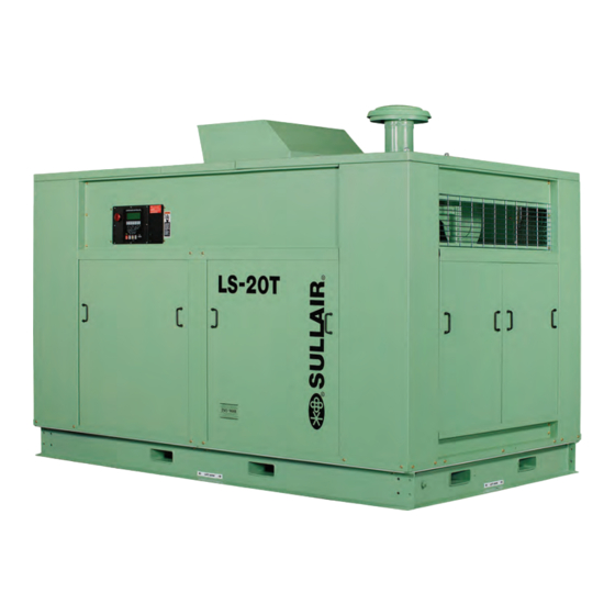
Section 2 DESCRIPTION 2.1 INTRODUCTION 2.4 COMPRESSOR COOLING AND LUBRICATION Your new Sullair lubricated rotary screw air com- SYSTEM, FUNCTIONAL DESCRIPTION pressor will provide you with a unique experience in Refer to Figures 2-2, and 2-3. The cooling and improved reliability and greatly reduced mainte- lubrication system consists of a fluid cooler, nance. - Page 12 Section 2 DESCRIPTION Figure 2-1 Sullair Series LS20TS Rotary Screw Compressor- Water-cooled (Typical)
- Page 13 Section 2 DESCRIPTION Figure 2-2 Compressor Cooling, Lubrication and Discharge System significantly reduced, thus causing large droplets of Sight glasses are located in the return lines to fluid to form and fall to the bottom of the observe this fluid flow. There are also orifices in this receiver/sump.
- Page 14 Section 2 DESCRIPTION The receiver is an ASME pressure vessel. A combi- compressor with any other pressure range would nation minimum pressure/check valve, located operate in a similar manner except for the stated downstream from the separator, assures a mini- pressures.
- Page 15 Section 2 DESCRIPTION control pressure regulator valve modulates the inlet earlier. This cycle will repeat itself, maintaining the poppet valve. demand required on the system line supply. UNLOAD MODE - EXCESS OF 535 PSIG (36.8 SHUTDOWN MODE BAR) When the compressor is shut down based on a As the required air is reduce, the discharge pres- manual shutdown, a safety shutdown or an auto- sure and line pressure rise above the 535 psig (36.8...
- Page 16 Section 2 DESCRIPTION Figure 2-3 Compressor Piping and Instrumentation Diagram- LS20T 250-300 525 PSIG 02250139-843R01...
- Page 17 Section 2 DESCRIPTION Figure 2-3 Compressor Piping and Instrumentation Diagram- LS20T 250-300 525 PSIG part number description number quantity filter, air 048456 valve, poppet 02250138-707 compressor, h.p. unit compressor, h.p. unit 2nd stage p,rtd 100 ohm 250039-909 xdcr,press 0-750# 1-5vdc n4...
- Page 18 Section 2 DESCRIPTION Figure 2-3 Compressor Piping and Instrumentation Diagram- LS20T 250-300 525 PSIG 02250139-843R01...
- Page 19 Section 2 DESCRIPTION Figure 2-3 Compressor Piping and Instrumentation Diagram- LS20T 250-300 525 PSIG (continued) part number description number quantity valve, solenoid 3-way n.o. 02250125-657 valve, solenoid 3-way n.o. 407390 regulator, back pressure 02250139-080 valve, relief gearbox-150psi 02250107-045 glass, sight 02250126-129 orifice, 3/32”...
- Page 20 Section 2 DESCRIPTION Figure 2-4A Control System Diagram- Functional Components...
- Page 21 Section 2 DESCRIPTION Figure 2-4B Control System Diagram- START...
- Page 22 Section 2 DESCRIPTION Figure 2-4C Control System Diagram- MODULATION...
- Page 23 Section 2 DESCRIPTION Figure 2-4D Control System Diagram- FULL LOAD...
- Page 24 Section 2 DESCRIPTION Figure 2-4E Control System Diagram- UNLOAD...
-
Page 25: Control Capacity System, Functional Description
Section 2 DESCRIPTION 2.7 AIR INLET SYSTEM, FUNCTIONAL DESCRIP- Figure 2-5 Air Inlet System TION Refer to Figure 2-5. The Compressor Inlet System consists of a dry-type air filter, a vacuum switch, and an air inlet valve. At 20” water column the inlet vacuum switch will allow the Supervisor Controller to indicate that “AIR FILTER MAINT”... - Page 26 NOTES...
-
Page 27: Specifications- Ls20T (525 Psig)
92.09 2339 (II) (II) (I) Enclosure height = 73.87in/ 1876mm. (II) For information concerning compressor weight, please contact the Sullair Factory Sales Department. For noise level information, please contact the Sullair Factory Service Department. COMPRESSOR: Type: 2-Stage Oil Flooded Rotary Maximum Full Load Operating Pressure: 525 psig (36.1 bar) -
Page 28: Application Guide
Section 3 SPECIFICATIONS 3.3 APPLICATION GUIDE Sullair encourages the user to participate in a fluid Mixing of other lubricants within the compressor analysis program with the fluid suppliers. This could unit will void all warranties result in a fluid change interval differing from that “The Plastic Pipe Institute recommends against... - Page 29 Section 3 SPECIFICATIONS Figure 3-2 Identification- LS20T 250-300 525# Water-cooled with Supervisor Controller 02250139-799R00...
- Page 30 NOTES...
-
Page 31: Mounting Of Compressor
It is recom- created across the fan. Consult a Sullair office for mended that the frame be grouted to the founda- assistance in utilizing this heat. - Page 32 With the control system in MANUAL MODE, pull out Sullair provides a wiring diagram for use by the the EMERGENCY STOP button and press once, installer.
- Page 33 Section 5 SUPERVISOR CONTROLLER Figure 5-1 Supervisor Controller Panel For information concerning all aspects of the Supervisor Controller, consult the Supervisor Controller manual no. 02250133-517.
- Page 34 NOTES...
-
Page 35: General
OPERATION 6.1 GENERAL will call for service or indicate the beginning of a While Sullair has built into this compressor a com- malfunction. Before starting your Sullair compres- prehensive array of controls and indicators to sor, read this section thoroughly and familiarize... -
Page 36: Initial Start-Up Procedure
Section 6 OPERATION 6.2 PURPOSE OF CONTROLS (CONTINUED) CONTROL OR INDICATION PURPOSE BLOWDOWN SOLENOID VALVE Opens when a demand for an unload/shutdown condition exists. When valve is opened, it will supply air to the blow- down valve. BLOWDOWN VALVE Vents sump pressure to the atmosphere during unload/shut- down conditions. -
Page 37: Maintenance Introduction
Section 7 MAINTENANCE 7.1 MAINTENANCE INTRODUCTION 4-46 fluid should be changed under the following The Supervisor Controller monitors the status of conditions, whichever occur first: the air filter, fluid filter, and separator elements. 1. Every 1200-1400 hours. When maintenance to these devices is required, 2. -
Page 38: Air Filter Maintenance
As previously ture, it is important that ONLY replacement ele- ments identified with the Sullair name, logo and stated, the Supervisor Controller will alert you as to appropriate part numbers be used, and that sub-... -
Page 39: Separator Maintenance
1. Place a bright light inside the element to inspect for damage or leak holes. Concentrated light To assist with the removal of the tank lid, Sullair will shine through the element and disclose any has provided a 1”-8 nut to the top lid so it can be removed by a 1”-8 eye bolt (which is available... -
Page 40: Oil Return/Sight Glass Maintenance
Section 7 MAINTENANCE Figure 7-3 Separator Element Replacement 8. Clean the fluid return line orifice installed in the side of the compressor unit air end. OIL RETURN/SIGHT GLASS MAINTENANCE Refer to Figure 7-4. The oil return/sight glass sub- assembly is attached to the separator tank. Oil return/sight glass maintenance should be per- formed on a routine basis parallel to that of the fluid filter, or as indicated in the Troubleshooting Section... -
Page 41: Differential Pressure Regulator Adjustment
Section 7 MAINTENANCE DIFFERENTIAL PRESSURE REGULATOR Figure 7-5 Pressure Regulator Adjustments ADJUSTMENT Refer to Figure 7-5. The differential pressure regu- lators are adjusted by loosening the adjusting screw on the end of the cone-shaped cover of the pres- sure regulator. When the jam nut is loose, turn the adjusting screw clockwise to increase or counter- clockwise to decrease the setting. - Page 42 NOTES...
-
Page 43: Troubleshooting
Should your problem persist after making the rec- nent replacement procedures. ommended check, consult your nearest Sullair rep- resentative or the Sullair Corporation factory. A detailed visual inspection is worth performing for almost any problems which may prevent unneces- 8.2 TROUBLESHOOTING GUIDE... - Page 44 Section 8 TROUBLESHOOTING 8.2 TROUBLESHOOTING GUIDE(CONTINUED) SYMPTOM PROBABLE CAUSE REMEDY Cooler plugged; clean tubes. If plugging per- COMPRESSOR SHUTS DOWN High Discharge Temperature (Cont.) sists, install water conditioner. (water-cooled). (CONTINUED) Low fluid level; add fluid. Clogged filter; change the fluid filter element if maintenance indicator shows red, and/or dP2 on controller indicates high dP.
- Page 45 Section 8 TROUBLESHOOTING 8.2 TROUBLESHOOTING GUIDE (CONTINUED) SYMPTOM PROBABLE CAUSE REMEDY Check all pipes, connections and compo- EXCESSIVE COMPRESSOR Leak in the Lubrication System nents. LUBRICANT CONSUMPTION (CONTINUED) Drain fluid and change. Excessive Fluid Foaming Drain excess fluid. Fluid Level Too High Readjust below pressure relief valve setting.
- Page 46 NOTES...
-
Page 47: Procedure For Ordering Parts
ILLUSTRATIONS AND PARTS LIST 9.1 PROCEDURE FOR ORDERING PARTS Parts should be ordered from the nearest Sullair Representative or the Representative from whom the com- pressor was purchased. If for any reason parts cannot be obtained in this manner, contact the factory directly at the addresses, phone or fax numbers below.When ordering parts always indicate the Serial Number of the... - Page 48 Section 9 ILLUSTRATIONS AND PARTS LIST 9.2 SPARE PARTS LIST- LS20T (525 PSIG) (CONTINUED) DESCRIPTION KIT NUMBER Repair kit for shaft seal 001811A Replacement drive-coupling element (250-300hp/186-224kw) (I)(II) 02250075-399 Replacement drive-coupling element (350hp/261kw) (I)(II) 250006-267 LLL-4-46 fluid (5-gal can) 249775-001 25-gal (I) Recommended spare parts.
- Page 49 NOTES...
-
Page 50: Motor, Frame, Compressor And Parts
Section 9 ILLUSTRATIONS AND PARTS LIST 9.3 MOTOR, FRAME, COMPRESSOR AND PARTS 02250137-909R00... - Page 51 350HP/261KW: drive coupling replacement no. 250006-267. (III) There is an exchange program whereby a remanufactured compressor unit can be obtained from Sullair distributors or the factory at less cost than the owner could repair the unit. For information regarding the unit exchange program, contact your nearest Sullair representative or the Sullair Corporation.
-
Page 52: Air Inlet System
Section 9 ILLUSTRATIONS AND PARTS LIST 9.4 AIR INLET SYSTEM 02250137-907R03... - Page 53 Section 9 ILLUSTRATIONS AND PARTS LIST 9.4 AIR INLET SYSTEM part number description number quantity orifice,.040 1/4fnpt x 1/4mnpt 02250091-395 tube, 7” x 6.5” w/3/8” conn 02250120-368 pipe, 6” aluminum 150# (m) 02250126-548 tube,alum air inlet 7”od x 13” 02250135-629 sub assembly, 6.50”invlv w/orif 20t 575# (I) 02250138-707 hose, hump 7”...
- Page 54 Section 9 ILLUSTRATIONS AND PARTS LIST 9.4 AIR INLET SYSTEM 02250137-907R03...
- Page 55 Section 9 ILLUSTRATIONS AND PARTS LIST 9.4 AIR INLET SYSTEM (CONTINUED) part number description number quantity bushing, red pltd 1/2 x 3/8 867102-015 elbow, pipe-90m 1/4 x 1/4 ss 872204-025 plug, str thd hol hx 1 5/16-12 875716-131 tee, pipe 300# 1/4 ss 876730-010 connector, tube-m 1/4 x 1/4 ss 876804-025...
-
Page 56: Air Inlet Sub-Assembly
Section 9 ILLUSTRATIONS AND PARTS LIST 9.5 AIR INLET SUB-ASSEMBLY 02250138-702R00... - Page 57 Section 9 ILLUSTRATIONS AND PARTS LIST 9.5 AIR INLET SUB-ASSEMBLY (I) part number description number quantity housing, body 6.5” inlet valve 02250054-750 shaft, 6.50” inlet valve 02250054-756 cover, inter 6.50”valve 02250054-757 piston, 6.50 inlet valve 02250054-759 spring, compresion, 1.50 lbs 02250054-761 cover, assembly 6.50”...
-
Page 58: Water Cooling System
Section 9 ILLUSTRATIONS AND PARTS LIST 9.6 WATER COOLING SYSTEM 02250137-908R00... - Page 59 Section 9 ILLUSTRATIONS AND PARTS LIST 9.6 WATER COOLING SYSTEM part number description number quantity cooler, oil/wtr 06054 575# 300hp 02250138-166 cooler, air/wtr 06036 575# 300hp 02250138-167 nut, hex pltd 1/2-13 825208-448 capscr, hex gr5 1/2-13 x 1 1/4 829108-125 capscr, hex gr5 1/2-13 x 1 1/2 829108-150 washer, spr lock reg pltd 1/2...
-
Page 60: Air Piping System
Section 9 ILLUSTRATIONS AND PARTS LIST 9.7 AIR PIPING SYTEM 02250137-910R01... - Page 61 2 w/1/4”tap 02250110-165 valve, ball 3/4” npt apollo 02250117-792 separator, water vert ls20t 600# 02250138-527 tube, msep/out ls20t wc 575# 02250138-577 tube, mpv/clr ls20t wc 575# 02250138-579 plate, cust conn ls20t 2”npt 02250138-589...
-
Page 62: Fluid Piping System
Section 9 ILLUSTRATIONS AND PARTS LIST 9.8 FLUID PIPING SYSTEM 02250137-912R01... - Page 63 80cn full flow 575# 02250138-316 mount, fltr plt 80cn 575# 02250138-317 tube, thrmvlv/clr ls20t 575# 02250138-571 tube, clr/thrmvlv ls20t wc 575# 02250138-573 tube, thrmvlv/fltr ls20t wc 575# 02250138-575 nipple, pipe-xs 316s 1/4 x cl 250019-142 fitting, compress non-adj d 250028-633 probe, rtd 100 ohm plat 3.5”x 12ft...
-
Page 64: Water Piping System
Section 9 ILLUSTRATIONS AND PARTS LIST 9.9 WATER PIPING SYSTEM 02250139-798R00... - Page 65 2w nc 1 1/2” 150#vac n4 (I) 02250125-653 support, water conn 1-1/2”npt 02250138-590 tube, clg wtr in ls20t-200/300 02250139-805 tube, clg wtr out ls20-200/300 02250139-807 tube, clr/clr ls20t-200/300 575 02250139-809 valve, globe 1-1/2” 125lb 047834...
-
Page 66: Discharge System
Section 9 ILLUSTRATIONS AND PARTS LIST 9.10 DISCHARGE SYSTEM 02250137-911R01... - Page 67 02250126-129 valve, assy 3”x m85 (III) 02250127-507 nut, hex m85-2 6h 02250130-997 plate, scav line assy - ls20t 02250132-464 boom, ls16t sump head lifting 02250135-164 tank, air-oil separator ls20t 575# 02250137-929 plate, separator hold down ls20t 575#...
- Page 68 Section 9 ILLUSTRATIONS AND PARTS LIST 9.10 DISCHARGE SYSTEM 02250137-911R01...
- Page 69 575# 02250138-751 valve, relief 1 x 1-1/2 575# ls20t 02250140-330 plug, o-ring boss sae 1 1/4 040029 valve, pneu (nc) 500# rn bdv (IV) 045116 orifice, 1/2m x 1/2f x .156 234125-156 gasket, asa flange 300# 2-1/2”...
- Page 70 Section 9 ILLUSTRATIONS AND PARTS LIST 9.10 DISCHARGE SYSTEM 02250137-911R01...
- Page 71 Section 9 ILLUSTRATIONS AND PARTS LIST 9.10 DISCHARGE SYSTEM (CONTINUED) part number description number quantity elbow, tube 90 deg m 1/4 x 1/4 ss 877004-025 elbow, tube 90 deg m 1/2 x 1/2 ss 877008-050 elbow, female str thd 1 1/16 878312-106 tee, pipe 1/2”...
-
Page 72: Control/Start System
Section 9 ILLUSTRATIONS AND PARTS LIST 9.11 CONTROL/START SYSTEM 02250137-914R02... - Page 73 3wno 1/4 235# n4 (II) 02250125-657 transducer, pressure 0-750psi 1-5vdc n4 02250134-099 starter assembly consult factory support, bracket fltr assy ls20t 575# 02250138-840 valve, pressure reducing 1/4” vit 2-150# (III) 02250139-030 valve, pressure regulator 1/4” 200-575#set (IV) 02250139-080...
- Page 74 Section 9 ILLUSTRATIONS AND PARTS LIST 9.11 CONTROL/START SYSTEM 02250137-914R02...
- Page 75 Section 9 ILLUSTRATIONS AND PARTS LIST 9.11 CONTROL/START SYSTEM (CONTINUED) part number description number quantity nut, hex f pltd 3/8-16 825306-347 capscr, hex gr5 3/8-16 x 1 829106-100 capscr, hex gr5 1/2-13 x 1 1/2 829108-150 screw, hex ser washer 1/4-20 x 1/2 829704-050 screw, hex ser washer 5/16-18 x 1/2 829705-050...
-
Page 76: Control Panel
Section 9 ILLUSTRATIONS AND PARTS LIST 9.12 CONTROL PANEL 02250138-633R00... - Page 77 Supervisor II 02250048-822 panel, cover Supervisor II 02250054-854 nameplate, Sullair serial number 02250059-318 gasket, ctl pnl super II 02250071-093 grip, cord n4 .250-.375 x 1/2” 02250071-381 control, Supervisor III display mod 02250119-330 decal, Supervisor front...
-
Page 78: Enclosure
Section 9 ILLUSTRATIONS AND PARTS LIST 9.13 ENCLOSURE 02250138-672R00... - Page 79 02250103-203 panel, assembly end 20/25 enclosure 02250103-205 panel, assembly side 20/25 enclosure 02250116-349 hinge, door 02250125-402 door,can-ts20 elem roof access 02250132-711 panel, roof enclosure ls20t 575# 02250138-674 grommet,rubber 040125 clamp, wire 043194 support member, 20-25 encl 231516 guard,fan 20” diameter...
- Page 80 Section 9 ILLUSTRATIONS AND PARTS LIST 9.13 ENCLOSURE 02250138-672R00...
- Page 81 Section 9 ILLUSTRATIONS AND PARTS LIST 9.13 ENCLOSURE (CONTINUED) part number description number quantity screw, hex ser washer 1/4-20 x 3/4 829704-075 screw, hex ser washer 5/16-18 x 3/4 829705-075 screw, hex ser washer 5/16-18 x 1 829705-100 washer, spr lock reg pltd 3/8 837806-094 washer, pl-b reg pltd 5/16 838205-071...
- Page 82 Section 9 ILLUSTRATIONS AND PARTS LIST 9.14 DECAL GROUP...
- Page 83 Section 9 ILLUSTRATIONS AND PARTS LIST 9.14 DECAL GROUP part number description number quantity sign, air breathing (danger) 250027-935 sign, warning “food grade” lube 250003-144 sign, warning ground fault 049852 decal, warning auto start 250017-903 sign, danger electrocution 049850 sign, warning hot surfaces 407408 sign, warning sever - fan 049855...
- Page 84 Section 9 ILLUSTRATIONS AND PARTS LIST 9.14 DECAL GROUP...
-
Page 85: Decal Group
Section 9 ILLUSTRATIONS AND PARTS LIST 9.14 DECAL GROUP (CONTINUED) part number description number quantity sign, warning “compressor fluid fill cap” 049685 decal, warning mixing fluids 02250110-891 decal, danger high voltage 042218 decal, rotation 250021-564 decal, rotation 250021-286 decal, fluid LLL-4-46 02250145-602 decal, water inlet-outlet 049873... - Page 86 Section 9 ILLUSTRATIONS AND PARTS LIST 9.14 DECAL GROUP...
- Page 87 02250075-045 decal, earth ground 02250075-046 decal, PE designation 02250075-540 decal, electrical component ID 250038-457 decal, LS-20T black 4” ht. 02250071-287 decal, Sullair logo 4 x 32” black 02250059-060 PLEASE NOTE: WHEN ORDERING PARTS, INDICATE THE SERIAL NUMBER OF COMPRESSOR...
-
Page 88: Decal Location- Open Model
Section 9 ILLUSTRATIONS AND PARTS LIST 9.15 DECAL LOCATION- OPEN MODEL... - Page 89 - fan 049855 decal, LS20T black 4” ht. 02250071-287 decal, water drain 250022-810 decal, ISO 9001 02250057-624 decal, Sullair logo 4 x 32” black 02250059-060 decal, fork lifting 241814 sign, warning hot surfaces 407408 decal, warning mixing fluids 02250110-891...
-
Page 90: Decal Location- Enclosed Model
Section 9 ILLUSTRATIONS AND PARTS LIST 9.16 DECAL LOCATION- ENCLOSED MODEL... - Page 91 041065 decal, LS20T black 4" ht. 02250071-287 decal, ISO 9001 02250057-624 decal, fork lifting 241814 decal, Sullair logo 4 x 32" black 02250059-060 sign, warning sever-fan port 049965 sign, warning "compressor fluid fill cap" 049685 decal, rotation 250021-564...
-
Page 92: Decal Location- Control Box
Section 9 ILLUSTRATIONS AND PARTS LIST 9.17 DECAL LOCATION- CONTROL BOX... - Page 93 02250075-046 (I) Due to custom voltage requests, voltage decal may vary. For positive identification of machine volt- age decal, consult Sullair Factory with serial number of compressor. PLEASE NOTE: WHEN ORDERING PARTS, INDICATE THE SERIAL NUMBER OF COMPRESSOR...
-
Page 94: Wiring Diagram- Ls20Ts (525 Psig)
Section 9 ILLUSTRATIONS AND PARTS LIST 9.18 WIRING DIAGRAM- LS20T 525 PSIG 02250137-917R01... - Page 95 NOTES...
- Page 96 WORLDWIDE SALES AND SERVICE SULLAIR ASIA, LTD. SULLAIR EUROPE, S.A. Sullair Road, No. 1 Zone Des Granges BP 82 Chiwan, Shekou 42602 Montbrison Cedex, France Shenzhen, Guangdong PRV. Telephone: 33-477968470 PRC POST CODE 518068 Fax: 33-477968499 Telephone: 755-6851686 www.sullaireurope.com Fax: 755-6853473 www.sullair-asia.com...
Need help?
Do you have a question about the LS20T and is the answer not in the manual?
Questions and answers