Table of Contents
Advertisement
Quick Links
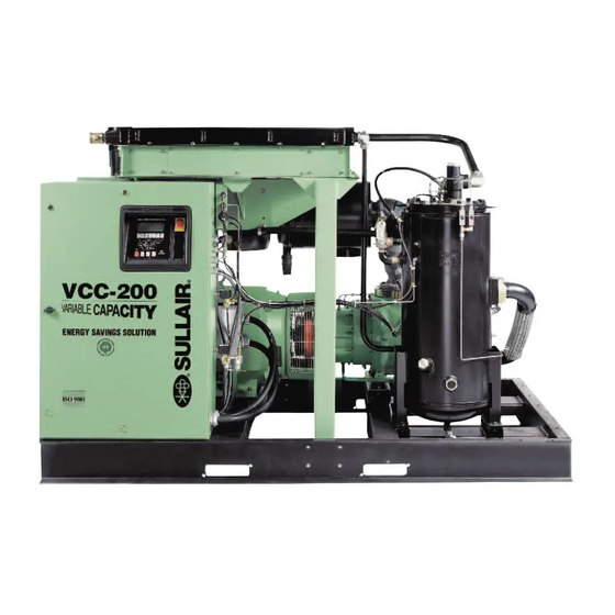
VCC-2 2 00
AIR-COOLED AND WATER-COOELD
SERIES MODEL DESIGNATIONS:
LS
Lubricated Screw Compressor
V
Variable Speed Drive Compressor
VCC
Variable Capacity Compressor
INDUSTRIAL AIR
COMPRESSOR
LS-2 2 00
200
100HP/ 75KW
STANDARD AND 24KT
OPERATOR'S
MANUAL AND
PARTS LIST
KEEP FOR
FUTURE
REFERENCE
Part Number
02250145-907
©Sullair Corporation
Advertisement
Table of Contents


Need help?
Do you have a question about the LS-200 and is the answer not in the manual?
Questions and answers