
Related Manuals for Leadshine iSV2-CAN Series


Summary of Contents for Leadshine iSV2-CAN Series
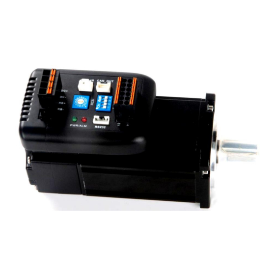
- Page 1 User Manual of iSV2-CAN Servo User Manual Of iSV2-CAN Series Integrated Servo Motor Prelimilary version 0.01 www.leadshine.com...
-
Page 2: Introduction
User Manual of iSV2-CAN Servo Introduction Thanks for purchasing Leadshine iSV2 series integrated servo motor, this instruction manual provides knowledge and attention for using this motor. Contact tech@leadshine.com for more technical service . Incorrect operation may cause unexpected accident, please read this manual carefully before using product. - Page 3 ⚫ The rate torque of servo motor should be larger than effective continuous load torque. ⚫ The ratio of load inertia and motor inertia should be smaller than recommended value. ⚫ The servo drive should be matched with servo motor. www.leadshine.com...
-
Page 4: Table Of Contents
4.2.5【Class 4】I/F Monitor Setting ..................36 4.2.6【Class 5】Extended Setup....................41 4.2.7【Class 6】Special Setup ....................44 4.2.8【Class 7】Factory setting.....................46 4.3 402 Parameters Function......................47 Chapter 5 CANopen ...........................52 5.1 CAN Interface ........................52 5.2 CANopen protocol .........................52 5.2.1 CANopen frame ......................52 5.2.2 CANopen objects ......................53 www.leadshine.com... - Page 5 6.8 Homing mode ........................72 6.8.1 Controlword in profile homing mode ................72 6.8.2 Statusword in profile homing mode ................73 6.8.3 Related objects......................74 6.8.4 Example of homing mode....................74 6.8.5 Homing Method......................75 6.9 Security Features ........................89 6.9.1 BRK-OFF output ......................89 6.9.2 Servo stop mode ......................91 www.leadshine.com...
- Page 6 6.13 Regenerative resister setting ....................94 Chapter 7 Alarm and Processing......................96 7.1 Alarm List..........................96 7.2 Alarm Processing Method .......................97 Chapter 8 Product Specification ......................105 8.1 Drive Technical Specification ....................105 8.2 Accessory selection ......................106 Contact us ............................107 www.leadshine.com...
-
Page 7: Chapter 1 Introduction
4000 Rated Voltage(Vdc) Weight(kg) 0.95 1.25 24~70 24 -70 Input Voltage(Vdc) 24~70 Continuous Current(Arms) Peak Current(A) Logic Signal Current(mA) Isolation Resistance(MΩ) Control method IGBT PWM sinusoidal Wave Drive Overload 250% ~ 300% Brake resistor External connection Protection rank IP54 www.leadshine.com... -
Page 8: Part Numbering Information
Check the following thing before using the products : a. Check if the product is damaged or not during transportation. b. Check if the servo drive & motor are complete or not. c. Check the packing list if the accessories are complete or not www.leadshine.com... -
Page 9: Chapter 2 Installation
Motor shaft does not bear the axial load, radial load, otherwise you may damage the motor. ⚫ Use a flexible with high stiffness designed exclusively for servo application in order to make a radial thrust caused by micro misalignment smaller than the permissible value. ⚫ Install must be steady, prevent drop from vibrating. www.leadshine.com... -
Page 10: Chapter 3 Wiring
When it rises to a certain voltage value, the excess energy needs to be consumed by the regenerative resistance The recommended regenerative resistance specifications for the iSV2 series are as follows: Recommend resister value (Ω) Drive Recommend resister power (W) iSV2-CAN6020V48 iSV2-CAN6040V48 iSV2-CAN8075V48 www.leadshine.com... - Page 11 10Ω+/-5%, 100w RXFB-1, Part num Code : 10100469 Attention ⚫ Match the colors of the motor lead wires to those of the corresponding motor output terminals (U.V.W) ⚫ Never start nor stop the servo motor with this magnetic contactor. www.leadshine.com...
-
Page 12: Wiring
4.7K 4.7K COM_OUT RS232 Figure 3.1 Position Control Mode Wiring Notes: 1. 4 digital inputs DI3~DI6, support NPN and PNP connection, recommend 12~24V input signal. 2. 2 digital outputs DO1~DO2, support NPN and PNP connection, recommend 24V output signal. www.leadshine.com... -
Page 13: Drive Terminals Function
(NOT), low level available in default , max voltage is 24V input 20KHz Output Digital output signal 1 , default value is alarm output,24V, <100mA Digital output signal 2 , default value is servo-ready output,24V, Output <100mA COMO Output Digital output signal commonality ground, 24V www.leadshine.com... -
Page 14: Power Port
Power Ground (Negative) Regenerative resistor + RBR+ Regenerative resistor - RBR- The recommend resistor for most application is 10Ω+/-5%, 100watt Leadshine can provide resistor: RXFB-1, Part num Code : 10100469 3.2.3 Communication Port Signal RS232 3.2.4 CAN bus connector Signal... -
Page 15: I/O Interface Principle
Digital Input function allocation Name Input selection DI3 Mode Pr4.02 — Range 0~00FFFFFFh Unit Default 0x14 Index 2402h Name Input selection DI4 Mode Pr4.03 — Range 0~00FFFFFFh Unit Default 0x16 Index 2403h www.leadshine.com... - Page 16 I/O input digital filtering; higher setup will arise control delay. Digital Output function allocation Name Output selection DO1 Mode Pr4.10 — Range 0~00FFFFFFh Unit Default Index 2410h 0x01 Name Output selection DO2 Mode Pr4.11 — Range 0~00FFFFFFh Unit Default Index 2411h 0x02 www.leadshine.com...
- Page 17 Speed command ON/OFF output V-CMD Servo enable state output SRV-ST Homing process finish HOME-OK · Normally open:Active low · Normally closed:Active high · Don’t setup to a value other than that specified in the table . · Pr4.10~Pr4.11 correspond to DO1~DO2 respectively. www.leadshine.com...
-
Page 18: Chapter 4 Parameter
Adjust 2107h Pr_107 velocity loop integration 2nd filter of velocity 2108h Pr_108 detection 2nd time constant of 2109h Pr_109 torque filter 2110h Pr_110 Velocity feed forward gain Velocity feed forward 2111h Pr_111 filter Torque feed forward gain 2112h Pr_112 www.leadshine.com... - Page 19 2436h Pr_436 At-speed Mechanical brake action 2437h Pr_437 setting when stopping Mechanical brake action 2438h Pr_438 setting Brake release speed setup 2439h Pr_439 2443h Pr_443 E-stop function active Drive inhibit input setup 2504h Pr_504 Sequence at servo-off 2506h Pr_506 www.leadshine.com...
- Page 20 2620h Pr_620 waiting time of trial 2621h Pr_621 running cycling times of trial 2622h Pr_622 running Acceleration of trial 2625h Pr_625 running Mode of trial running 2626h Pr_626 Frame error window time 2634h Pr_634 Frame error window 2635h Pr_635 www.leadshine.com...
-
Page 21: Manufacturer Parameters (Group 5000H)
832h Alarm detection 0000 Sync0 Bit0: 818h Alarm enable switch Bit1: 819h Bit2: 81Ah Bit3: 824h Bit4: 825h Synchronous alarm 0xFFF 0xFFF Bit5: Reserved 5006 setting Bit6: Reserved Bit7: 82Ch Bit8: 82Dh Bit9: 832h Bit10~15: Reserved Notes: 0 invalid;1 valid www.leadshine.com... - Page 22 Unit 32 bit low The actual mechanical position Unit 32 bit high Number of encoder communication exceptions Motor Speed r/min Speed of position r/min command Speed command r/min 5501 Actual torque 0.1% Torque command 0.1% Relative position Pulse error www.leadshine.com...
-
Page 23: Device Profile Parameters (Group 6000H)
Actual internal position value unit Command 6064 Actual feedback position value unit Command 2147483 6065 Follow error window 10000 unit 6066 Follow error detection time 65535 Command 606B Internal command speed unit Command 606C Actual feedback speed value unit www.leadshine.com... - Page 24 Low speed of homing 5000 unit /s Command 2147483 609A Homing acceleration 10000 unit /s Command -214748 2147483 60B0 Position feedforward unit 3648 Velocity feedforward(Restricted by Command -214748 2147483 pp/pv/ 60B1 6080) unit /s 3648 0.1% 60B2 Torque feedforward -32768 32767 www.leadshine.com...
-
Page 25: Parameters Function
Supported operation mode 4.2 Parameters Function Here is the explanation of parameters, you can check them or modify the value using configuration software or the front panel of drive. Contact tech@leadshine.com if you need more technical service . 【 】 4.2.1... - Page 26 Pr1.00- 1.14, just change the value of Pr0.03 ,then all values of Pr1.00-1.14 will be changed Selection of machine stiffness at Name Mode Pr0.03 real- time auto-gain tuning — Range 50 ~ 81 Unit Default Index 2003h www.leadshine.com...
- Page 27 0~500 Unit 0.1rev Default Index 2014h Set excess range of positional deviation by the command unit(default).Setting the value too small will cause Err180 (position deviation excess detection) Name Absolute Encoder Setup Mode Pr0.15 Range 0~15 Unit Default Index 2015h www.leadshine.com...
- Page 28 CAN baud rate (KHz) Pr0.24 CAN baud rate (KHz) 1000 Name Synchronous compensation time 1 Mode Pr0.25 Range 1~100 Unit 0.1us Default Index 2025h Synchronous jitter compensation range, used in poor synchronization of the master station. Note:Valid after restart power. www.leadshine.com...
-
Page 29: Class 1】Gain Adjust
You can set the filter parameters through the loop gain, referring to the following table: Setup Speed Detection Filter Setup Speed Detection Filter Value Cut-off Frequency(Hz) Value Cut-off Frequency(Hz) 2500 2250 2100 2000 1800 1600 1500 1400 1300 1200 1100 1000 www.leadshine.com... - Page 30 Multiply the velocity control command calculated according to the internal positional command by the ratio of this parameter and add the result to the speed command resulting from the positional control process. Name Velocity feed forward filter Mode Pr1.11 Range 0~6400 Unit 0.01ms Default Index 2111h www.leadshine.com...
- Page 31 (level + hysteresis)[r/min]previously with the Speed command is 1st gain. large ⚫ Return to the 1st gain when the absolute value of the speed command was kept below (level + hysteresis) [r/min] previously during delay time with the 2nd gain. www.leadshine.com...
- Page 32 Name Mode switching Pr1.18 Mode Range 0~20000 Unit Default Index 2118h specific Combining Pr1.17(control switching level)setup Notice: when level< hysteresis, the hysteresis is internally adjusted so that it is equal to level. Pr1.19 Name position gain switching time Mode www.leadshine.com...
-
Page 33: Class 2】Vibration Suppression
After updated, Pr2.00 returns to 0, stop self-adaptation. Adaptive filter, 1 filter One adaptive filter is valid, parameters related to the is valid, It will be valid 3rd notch filter will be updated all the time based on all the time adaptive performance. www.leadshine.com... - Page 34 2000 Index 2207h Set the center frequency of the 3rd notch filter Notice: the notch filter function will be invalidated by setting up this parameter to “2000”. Setup invalid after opening self-adaptation function. Pr2.14 Name 1st damping frequency Mode www.leadshine.com...
-
Page 35: Class 3】Velocity/ Torque Control
⚫ When a square wave command for the target speed Vc is applied , set up the Vc arrival time as shown in the figure below. 【 】 4.2.4 Class 3 Velocity/ Torque Control Name time setup acceleration Mode Pr3.12 Range 0~10000 Unit Default Index 2312h (1000RPM) Pr3.13 Name time setup deceleration Mode www.leadshine.com... -
Page 36: Class 4】I/F Monitor Setting
Input selection DI4 Mode Pr4.03 — Range 0~00FFFFFFh Unit Default 0x16 Index 2403h Name Input selection DI5 Mode Pr4.04 — Range 0~00FFFFFFh Unit Default 0x01 Index 2404h Name Input selection DI6 Mode Pr4.05 — Range 0~00FFFFFFh Unit Default 0x02 Index 2405h www.leadshine.com... - Page 37 Speed command ON/OFF output V-CMD Servo enable state output SRV-ST Homing process finish HOME-OK · Normally open:Active low · Normally closed:Active high · Don’t setup to a value other than that specified in the table . · Pr4.10~Pr4.11 correspond to DO1~DO2 respectively. www.leadshine.com...
- Page 38 The hold time is maintained definitely, keeping ON state until next positional command is received. ON state is maintained for setup time (ms) but switched to OFF state as the 1-15000 positional command is received during hold time. Name Zero-speed Mode Pr4.34 Range 10~2000 Unit Default Index 2434h www.leadshine.com...
- Page 39 Because the speed coincidence detection is associated with 10 r/min hysteresis, actual detection range is as shown below. Speed coincidence output OFF -> ON timing (Pr4.35 -10) r/min Speed coincidence output ON -> OFF timing (Pr4.35 +10) r/min Name At-speed(Speed arrival) Mode Pr4.36 Range 10~2000 Unit Default 1000 Index 2436h www.leadshine.com...
- Page 40 Pr4.38 setup time, or time lapse till the motor speed falls below Pr4.39 setup speed. Name Brake release speed setup Mode Pr4.39 Range 30~3000 Unit Default Index 2439h Set up the speed timing of braking output checking during operation www.leadshine.com...
-
Page 41: Class 5】Extended Setup
You can set up the time to detect the shutoff while the main power is kept shut off continuously. The main power off detection is invalid when you set up this to 2000. Name Torque setup for emergency stop Mode Pr5.11 Range 0~500 Unit Default Index 2511h www.leadshine.com... - Page 42 The value of the parameter is limited to the maximum torque of the applicable motor. Compared with the maximum torque 6072, the actual torque limit value is smaller one Name LED initial status Mode Pr5.28 — Range 0~42 Unit Default Index 2528h www.leadshine.com...
- Page 43 Time compensation for signal acquisition of touch probe 2 to provide more accurate capture position and prevent the instantaneous jitter of capture during master and slave cooperation Torque saturation alarm detection Name Mode time Pr5.37 Range 0~5000 Unit Default Index 2537h www.leadshine.com...
-
Page 44: Class 6】Special Setup
Torque command additional Name Mode value Pr6.07 Range -100~100 Unit Default Index 2607h Positive direction torque Name Mode compensation value Pr6.08 Range -100~100 Unit Default Index 2608h Negative direction torque Name Mode compensation value Pr6.09 Range -100~100 Unit Default Index 2609h www.leadshine.com... - Page 45 The waiting time after running each time in JOG run(position control) Name Trial run cycle times Mode Pr6.22 — Range 0~32767 Unit Default Index 2622h The cycling times of JOG run(position control) Name Acceleration of trial running Mode Pr6.25 Range 0~32767 Unit Default Index 2625h Acceleration of trial running www.leadshine.com...
-
Page 46: Class 7】Factory Setting
Enable reactive pump lift suppression function Enable regenerative resistance discharge Notice: Name Regenerative resistance open threshold setting Mode Pr7.32 20~90 Range Unit Default The external resistance is activated when the actual bus voltage is higher than Pr7.32 plus Pr7.33 and is www.leadshine.com... -
Page 47: Parameters Function
Range Default PP, PV Mode :Stop according to 3506h(Sequence at Servo-off),keeping Switch on disabled :Stop according to 6084h(Profile deceleration),keeping Switch on disabled :Stop according to 6085h(Quick stop deceleration),keeping Switch on disabled :Stop according to 60C6h(Max deceleration),keeping Switch on disabled www.leadshine.com... - Page 48 Mode of operation display Structure Type int 8 Index TPDO 6061H Access Mapping Mode Range 0-10 Default Mode Profile position mode Profile velocity mode profile Torque mode Homing mode Index Name Actual internal position value Structure Type Dint 32 www.leadshine.com...
- Page 49 Command RPDO 6091H-02 Access Mapping Mode Range Default unit Set the number of pulses required for one motor rotation. Name Number of pulses per rotation Structure Type Dint 32 Index Command RPDO 6092H-01 Access Mapping Mode Range Default unit www.leadshine.com...
- Page 50 Z signal, the falling edge on the same side of homing switch must come before Z signal Search the homing point in negative direction, deceleration point is homing switch, homing point is motor Z signal, the rising edge on the same side of homing switch must come before Z www.leadshine.com...
- Page 51 DO1 valid valid Index Name Output enable Structure Type Uint 32 60FEH-0 Access Mapping Mode Range 0-ffff Default The bits of a 60FEh object are functionally defined as follow: 31~21 15~0 Sub-index Reserved Reserved enable enable enable enable enable enable www.leadshine.com...
-
Page 52: Chapter 5 Canopen
⚫ Process or system time synchronization. ⚫ Error state supervision. ⚫ Control and monitoring of node states. iSV2-CAN series follow the communication rules: ⚫ Comply with CAN 2.0A standard ⚫ Comply with CANopen standard protocol DS 301 _V4.02 ⚫ Comply with CANopen standard protocol DSP 402 _V2.01 5.2.1 CANopen frame... -
Page 53: Canopen Objects
Device profile area (0x6000 to 0x9FFF): These objects are standardized device profile objects as defined in the DSP402 profile, which is the CANopen profile for servo drives. This chapter is focused on the Communication profile area. DS301 defines special objects for the www.leadshine.com... -
Page 54: Nmt
The initialization state could be divided into three sub-states that are executed in a sequential way: Initializing (performs the basic CANopen initializations), Reset application (in where all manufacturer-specific and standardized profile area parameters are set) and Reset communication (where the communication profile and parameters are set). www.leadshine.com... -
Page 55: Nmt Services
The NMT Master can monitor the communication status of each node using the Node Guarding protocol. During node guarding, a controller is polled periodically and is expected to respond with its communication state within a pre-defined time frame. Note that responses indicating an acceptable state will alternate between www.leadshine.com... - Page 56 Data field(Byte 1) COB-ID(hex) Number of Bytes Bit 7 Bit 6 to 0 0x700+Node-ID Reserved NMT communication state The state of the heartbeat producer could be one of the followings: Communication State value(hex) State definition Boot-up Stopped Operational Pre-operational www.leadshine.com...
-
Page 57: Sdo
However, it is also possible to send information (up to 4bytes) during the initialization process. This mechanism is called SDO expedited transfer. The SDO message will be as follows: www.leadshine.com... -
Page 58: Pdo
A PDO communication parameter ⚫ A PDO mapping object iSV2-CAN series include 4 RPDO and 4 TPDO. Transmit PDO (TPDO) TPDOs are configured to send data from node to master after the occurrence of a trigger event or after a remote request by means of a RTR. -
Page 59: Sync
Zero or more emergency consumers may receive the emergency object. COB-ID(hex) Byte number: Emergency error codes Error registers Reserved 80+Node ID (Object 0x603F) (Object 0x1001) iSV2-CAN series include Emergency error codes (Object 0x603F): Emergency error codes Description 0000H 8110H CAN bus over-run www.leadshine.com... - Page 60 CAN Bus off occurred 8150H Send COB-ID conflicts 8210H PDO not processed due to length error 8220H PDO exceeds length error iSV2-CAN series include Error registers (Object 0x1001): Description Generic Error Current Voltage Temperature Communication Error specified by device protocol...
-
Page 61: Chapter 6 Trial Run
(speed motion parameters and control word). H.When the drive is finished executing the movement (position motion/velocity motion), iSV2-CAN feeds back the position/speed to the master station for monitoring during the motion I.The master station sends commands for the next motion. www.leadshine.com... -
Page 62: Cia 402 State Machine
The stop process is completed, and all the drive function are inhibited. Fault Parameter setting is allowed for users to eliminate faults. The conversion of CIA402 state machine is accomplished by the control word (6040h) of the iSV2-CAN servo system operated by the master station. www.leadshine.com... -
Page 63: Common Functions For All Modes
2、If 6092h_01(Feed constant) is equal to 608Fh(Position encoder resolution), then: Electronic gear ratio = 6091_01/6092h_01 Electronic gear ratio range is 1/1000~8000. Note: when the setting value exceeds this range, the error will be reported and automatically reset to the www.leadshine.com... -
Page 64: Control Word
Homing (PP) (PV) (PT) (HM) Halt Halt Halt Halt Abs / Rel Change set immediately Homing New set-point operation start 6.4.5 Status Word Bit definition of Status Word 6041h. The binary representation of the statusword (6041) is as follows: www.leadshine.com... -
Page 65: Drive Enable
Abnormal stop Abnormal stop 6.4.6 Drive Enable This section describes how to enable the drive by control word (6040h), how to view the drive enable states by status word (6041h) Steps: 1: Write 0 to the control word 6040h www.leadshine.com... -
Page 66: Profile Position Mode
If no positioning is in progress, the rising edge of bit 4 will start the positioning of the axis. In case a positioning is in progress, the definitions given in the following table shall be used. Change set Description www.leadshine.com... -
Page 67: Statusword In Profile Position Mode
Halt=0: Target position not reached Halt=1: Axis decelerates Target reached Halt=0: Target position reached Halt=1: Axis has velocity 0 No following error Following error Following error 6.5.3 Related objects Object Dictionary Description Setup value Units 6060H Mode of operation www.leadshine.com... -
Page 68: Example Of Profile Position Mode
According to the predetermined parameters, the profiler generates and provides the control unit with the instantaneous target torque to be achieved. Upon reaching the target, a statusword is issued as a notification to other nodes. www.leadshine.com... -
Page 69: Controlword In Profile Velocity Mode
Halt=1: Axis decelerates Target reached Halt=0: Target velocity reached Halt=1: Axis has velocity 0 Velocity is not equal 0 Velocity is 0 Velocity is equal 0 6.6.3 Related objects Object Dictionary Description Setup value Units 6060H Mode of operation www.leadshine.com... -
Page 70: Example Of Profile Velocity Mode
Upon reaching the target, a statusword is issued as a notification to other nodes. 6.7.1 Controlword in profile torque mode The profile velocity mode uses some bits of the controlword and the statusword for mode specific purposes. www.leadshine.com... -
Page 71: Statusword In Profile Torque Mode
Halt = 0: Target torque reached Halt = 1: Axis has velocity 0 6.7.3 Related objects Object Dictionary Description Setup value Units 6060H Mode of operation 6040H Controlword 6041H Statusword 6071H Target torque 0.1% Torque change rate 6087H 0.1% www.leadshine.com... -
Page 72: Example Of Profile Torque Mode
6.8.1 Controlword in profile homing mode The profile velocity mode uses some bits of the controlword and the statusword for mode specific purposes. The binary representation of the controlword(6040) in profile homing mode is as follows: www.leadshine.com... -
Page 73: Statusword In Profile Homing Mode
Homing procedure is in progress Homing procedure is interrupted or not started Homing is attained but target is not reached Homing mode carried out successfully Homing error occurred; Homing mode carried out not successfully; Velocity is not zero www.leadshine.com... -
Page 74: Related Objects
Write the control word as 1f, set the 4th digit of 6040H as 1, start 40 60 00 1f 00 00 00 homing mode. Write the control word as 0f, and set the 4th digit of 6040H as 0, do 40 60 00 0f 00 00 00 not start homing mode. www.leadshine.com... -
Page 75: Homing Method
Start Position Stop Position High speed Low speed 6099h-01h 6099h-02h Method -2:Search the homing point with low speed negative direction, when the torque reached then reverse the direction, when the torque is gone and Z signal coming then stop immediately. www.leadshine.com... - Page 76 The motor stops after leaving the positive limit switch and the first encoder Z signal is valid, as shown in figure. If the negative limit signal is valid during the homing process, the status word (6041h) bit 13 will be valid, www.leadshine.com...
- Page 77 Z signal is valid, as shown in figure. If the positive/negative limit switch signal is valid during the homing process, the status word (6041h) bit 13 will be valid, indicating that the homing error and the motor will stop immediately. www.leadshine.com...
- Page 78 Z signal is valid, as shown in figure. If the positive/negative limit switch signal is valid during the homing process, the status word (6041h) bit 13 will be valid, indicating that the homing error and the motor will stop immediately. www.leadshine.com...
- Page 79 Then the motor reverse the direction at low speed. The motor stops after the homing switch valid and the first encoder Z signal is valid, as shown in figure. www.leadshine.com...
- Page 80 Z signal is valid, as shown in figure. If the negative limit switch signal is valid during the homing process, the status word (6041h) bit 13 will be valid, indicating that the homing error and the motor will stop immediately. www.leadshine.com...
- Page 81 If the negative limit switch signal is valid during the homing process, the status word (6041h) bit 13 will be valid, indicating that the homing error and the motor will stop immediately. High speed Low speed Start Position Stop Position 6099h-01h 6099h-02h Z signal HOME-SWITCH POT signal www.leadshine.com...
- Page 82 Z signal is valid, as shown in figure. If the positive limit switch signal is valid during the homing process, the status word (6041h) bit 13 will be valid, indicating that the homing error and the motor will stop immediately. www.leadshine.com...
- Page 83 If the positive limit switch signal is valid during the homing process, the status word (6041h) bit 13 will be valid, indicating that the homing error and the motor will stop immediately. Start Position Stop Position High speed Low speed 6099h-01h 6099h-02h Z signal HOME-SWITCH NOT signal www.leadshine.com...
- Page 84 Low speed 6099h-01h 6099h-02h Z signal HOME-SWITCH NOT signal Method 17: This method is similar to method 1 Start Position Stop Position High speed Low speed 6099h-01h 6099h-02h NOT signal Method 18: This method is similar to method 2 www.leadshine.com...
- Page 85 Start Position Stop Position High speed Low speed 6099h-01h 6099h-02h HOME-SWITCH Method 21: This method is similar to method 5 Start Position Stop Postion High speed Low speed 6099h-01h 6099h-02h HOME-SWITCH Method 22: This method is similar to method 6 www.leadshine.com...
- Page 86 High speed Low speed 6099h-01h 6099h-02h HOME-SWITCH POT signal Method 24: This method is similar to method 8 Start Position Stop Position High speed Low speed 6099h-01h 6099h-02h HOME-SWITCH POT signal Method 25: This method is similar to method 9 www.leadshine.com...
- Page 87 This method is similar to method 10 Start Position Stop Position High speed Low speed 6099h-01h 6099h-02h HOME-SWITCH POT signal Method 27: This method is similar to method 11 Start Position Stop Position High speed Low speed 6099h-01h 6099h-02h HOME-SWITCH NOT signal www.leadshine.com...
- Page 88 This method is similar to method 13 Start Position Stop Position High speed Low speed 6099h-01h 6099h-02h HOME-SWITCH NOT signal Method 30: This method is similar to method 14 Start Position Stop Position High speed Low speed 6099h-01h 6099h-02h HOME-SWITCH NOT signal www.leadshine.com...
-
Page 89: Security Features
Set up to prevent a micro-travel/drop of the motor (work) due to the action delay time(tb) of the brake. ⚫ After setting up Pr4.37>=tb, then compose the sequence so as the drive turns to servo-off after the brake is www.leadshine.com... - Page 90 *1:The delay time between SRV_ON and BRK_OFF is less than 500ms; *2:Time setting in Pr4.38; *3: The delay time between the BRK_OFF signal output and the actual brake release action, which depends on the hardware characteristics of the motor brake; *4:The smaller value of Pr4.37 and Pr4.39; www.leadshine.com...
-
Page 91: Servo Stop Mode
2、Click “CCW” to make motor run to CCW direction,click “Position 1” to save the position limit 1 Click “CW” to make motor run to CW direction,click “Position 2” to save the position limit 2 Click “Run” to start Inertia ratio identification. www.leadshine.com... -
Page 92: Vibration Suppression
3. Execute movement by controller or Motion Studio, drive will record notch frequency automatically. 4. Upload the drive parameters, the record notch frequency saved in Pr2.07. Read the value of Pr2.07, and set this value into Pr2.01. Then reset Pr2.07 to 2000. 5. Saving parameters setting. www.leadshine.com... - Page 93 Pr2.05 Range 0~20 Unit Default Index 2205h Set the width of notch at the center frequency of the 2nd notch filter. Notice: Higher the setup, larger the notch width you can obtain. Use with default setup in normal operation. www.leadshine.com...
-
Page 94: Friction Torque Compensation
Set Pr.0.16 and Pr.0.17 to confirm the threshold value of the discharge loop to give alarm for over current. Name Regenerative resistance control mode setting Mode Pr7.31 0~2 Range Unit Default Setup value Details Disable regenerative resistance discharge Enable reactive pump lift suppression function www.leadshine.com... - Page 95 Regenerative resistance control hysteresis Mode Pr7.33 1~50 Range Unit Default The external resistance is activated when the actual bus voltage is higher than Pr7.32 plus Pr7.33 and is deactivated when the actual bus voltage is lower than Pr7.32 minus Pr7.33 Notice: www.leadshine.com...
-
Page 96: Chapter 7 Alarm And Processing
Read/write bus communication parameters error 5535 Read/write 402 parameters error 6321 input interface allocation error 6322 input interface function set error 6323 output interface function set error 6329 FPGA communication error 7122 Motor code error 7321 Encoder wiring error www.leadshine.com... -
Page 97: Alarm Processing Method
Display: “ ”--“ ” Error code Content: FPGA communication error Cause Confirmation Solution Check the voltage of Vdc/GND under-voltage Make sure voltage of Vdc/GND in proper range Vdc/GND terminal Drive internal fault replace the drive with a new one www.leadshine.com... - Page 98 Display: “ ” Error code Content: temperature detection circuit error Cause Confirmation Solution Vdc/GND under-voltage Check the voltage of Make sure voltage of Vdc/GND in proper range Vdc/GND terminal Drive inner fault replace the drive with a new one www.leadshine.com...
- Page 99 Short of drive output wire, whether Assure drive output wire no short Short of drive output wire short circuit to PG ground or not circuit, assure motor no damage Abnormal wiring of motor Check motor wiring order Adjust motor wiring sequence www.leadshine.com...
- Page 100 Check the load if it is inertia ,increase external regenerative resistor, regenerative resistor . too large or not. improve the capacity of the drive and motor Resistance discharge Increase external regenerative resistor, replace circuit damage the drive with a new one www.leadshine.com...
- Page 101 Communication data and shielded line if it is damaged or not; shielded line well with FG ground, abnormal check encoder cable whether it is ensure encoder cable separated with intertwined with other power wire or not other power wire www.leadshine.com...
- Page 102 (Pr_321) if it is proper or not; check encoder if the wiring assure encoder wiring correctly is correct or not Error Main Extra Display: “ ” www.leadshine.com...
- Page 103 Content: I/F input interface function set error Cause Confirmation Solution Check the value of Pr_410, Assure the value of Pr_410, Pr_411, The input signal are assigned Pr_411, Pr_412, Pr_413, if it is Pr_412,Pr_413 set correctly with two or more functions. proper or not www.leadshine.com...
- Page 104 Solution Forced-alarm input signal Check forced-alarm input signal Assure input signal wiring correctly has been conducted Main Extra Display: “ ” Error code Content: Motor code error Cause Confirmation Solution Motor code error Motor code error Set Pr7.15 correctly www.leadshine.com...
-
Page 105: Chapter 8 Product Specification
User Manual of iSV2-CAN Servo Chapter 8 Product Specification Notice Contact tech@leadshine.com if you need more technical service. 8.1 Drive Technical Specification Specifications Drive model iSV2-CAN6020V48** iSV2-CAN6040V48** iSV2-CAN8075V48** Rated Power(W) Rated Torque(Nm) 0.64 1.27 Peak Torque(Nm) 7.2Nm 1.92 3.81 Rated Speed(rpm) -
Page 106: Accessory Selection
User Manual of iSV2-CAN Servo 8.2 Accessory selection 1. Software configuration cable CABLE-PC-1 2. CAN communication cable CABLE-TX1M0-iSV2 CABLE-TX1M0-iSV2-LD2 CABLE-TX2M0-iSV2 CABLE-TX2M0-iSV2-LD2 3. Regenerative resistor(for application with big ACC and DEC ) 10Ω+/-5%, 100w RXFB-1, Part num Code : 10100469 www.leadshine.com... -
Page 107: Contact Us
Tel: 86-755-2641-8447 86-755-2641-8774 (for Asia, Australia, Africa areas) 86-755-2665-5136 (for America areas) 86-755-8654-2465 (for Europe areas) Fax: 86-755-2640-2718 Email: tech@leadshine.com (for All) Sales Tel: 86-755-2641-7674 (for Asia, Australia, Africa areas) 86-755-2640-9254 (for Europe areas) 86-755-2641-7617 (for America areas) Email: sales@leadshine.com...
Need help?
Do you have a question about the iSV2-CAN Series and is the answer not in the manual?
Questions and answers