Table of Contents
Advertisement
Quick Links
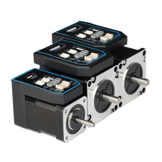
iCS-RS Series Modbus RS485
Integrated Closed Loop Stepper Motor
User Manual
©2022 Leadshine Technology Co., Ltd.
Address: 15-20/F, Block B, Nanshan I Valley, No.3185, Shahe West Road, Nanshan District,
Shenzhen, Guangdong, 518055, China
Tel: (86)755-26409254
Fax: (86)755-26402718
Web:
www.leadshine.com
Sales:
sales@leadshine.com
Support:
tech@leadshine.com
Advertisement
Table of Contents
Troubleshooting

Related Manuals for Leadshine iCS-RS Series


Summary of Contents for Leadshine iCS-RS Series
- Page 1 Series Modbus RS485 Integrated Closed Loop Stepper Motor User Manual ©2022 Leadshine Technology Co., Ltd. Address: 15-20/F, Block B, Nanshan I Valley, No.3185, Shahe West Road, Nanshan District, Shenzhen, Guangdong, 518055, China Tel: (86)755-26409254 Fax: (86)755-26402718 Web: www.leadshine.com Sales: sales@leadshine.com...
- Page 2 Strictly adhere to the technical information regarding installation requirements. This manual is not for use or disclosure outside of Leadshine except under permission. All rights are reserved. No part of this manual shall be reproduced, stored in retrieval form, or transmitted by any means, electronic, mechanical, photocopying, recording, or otherwise without approval from Leadshine.
- Page 3 Series Modbus RS485 Integrated Closed Loop Stepper Motor Safety Precautions Overall Notes Do not remove the housing with the drive powered on. Cables. Connectors and optional equipment. Please disconnect the power supply for at least 2 minutes and make sure the power indicator is off before wiring and checking.
- Page 4 Series Modbus RS485 Integrated Closed Loop Stepper Motor Precautions for Installation Please install the drive in a cabinet that provides fire protection. Electrical protection in the control cabinet. Please install the driver and motor in a position with sufficient weight resistance.
-
Page 5: Table Of Contents
Table of Content 1 Introduction ................................1 1.1 Product Introduction ............................ 1 1.2 Features ................................ 1 1.3 Application Scenarios ..........................1 1.3.1 Hands-on Tuning ..........................1 1.3.2 Practical Application Scenarios ......................1 2 Specifications ................................. 3 2.1 Electrical and Operating Specifications ....................... 3 2.2 Storage and Installation Conditions ...................... - Page 6 5.5.3 Fixed Trigger ..........................37 5.5.4 Immediate Trigger .......................... 37 6 Tuning Operations .............................. 39 6.1 Basic operation of Leadshine MotionStudio....................39 6.1.1 Preparation and Steps........................39 6.1.2 Operation of Trial Run ........................41 6.1.3 Operation of PR Function ....................... 42 6.2 Basic Operation of Serial Port Tools Software ..................
-
Page 7: Introduction
1 Introduction 1.1 Product Introduction iCS-RS Series is an integrated stepper motor integrated 14-bit incremental magnetic encoder and drive, and based on standard Modbus RTU protocol, using RS485 communication can network up to 31 axes. Its built-in PR feature with 16-segment position table (PR Mode) can save additional controllers in most of point-to-point applications, to greatly enhance system reliability and reduce the cost. - Page 8 Series Integrated Closed Loop Stepper Motor (2) Controlled by I/O (switch signal or PLC) The user only needs to turn off the switch signal to realize the PR motion, which is simple to control and low-cost design. Users can also use PLC I/O module to realize PR motion, which is more intelligent than switch signal control.
-
Page 9: Specifications
Series Integrated Closed Loop Stepper Motor 2 Specifications 2.1 Electrical and Operating Specifications Holding Power Peak Input Frame Length Weight Command Output Max Baud Digital Digital Model Torque Voltage Current Logical Size (mm) (Kg) Source Capability Rate Input Output (N.m) -
Page 10: Interface And Connection
Series Integrated Closed Loop Stepper Motor Models Length 47.14 4-φ5 57.2 MAX 21±0.5 L±1 iCS-RS2313 78 mm 22±0.5 iCS-RS2323 99 mm φ8 0.012 Figure 1: Mechanical specifications 3 Interface and Connection 3.1 Interface CN4: Tuning Port CN1: Power Input... -
Page 11: Cn1 &Cn2 Input Power Connector
Series Integrated Closed Loop Stepper Motor RS232 tuning connector Salve ID: SW1-SW5 SW6-SW7 DIP Switch Baud Rate: Terminal Resistance: SW8 3.1.2 CN1 &CN2 Input Power Connector Name Signal Description 20V- 36V Name Signal Description Configurable Single-ended Digital Inputs DI1-DI7, 12V - 24V. -
Page 12: Cn4-Rs232 Tuning Port
3.1.3 CN4-RS232 Tuning Port Name Signal 3.1.4 DIP Switches The iCS-RS series use an 8-bit DIP switched to set Salve ID (also called Site Alias), Baud Rate and Terminal Resistance, they are shown as below: Baud Rate 120Ω Terminal Slave ID... -
Page 13: Wiring Instructions
Series Integrated Closed Loop Stepper Motor Note: (1) When the SW1-SW5 is default (all are on), the Slave ID can be configured by the PC software (2) Baud Rate: SW6 - SW7 Baud Rate 115200 38400 (Factory) 19200 9600... -
Page 14: Power Supply Cable
Series Integrated Closed Loop Stepper Motor Figure 3.1 Wiring Instructions Note: (1) There are two RS485 communication ports above, one of them is input port which connects with master station or previous slave, and the other is output port which connects with the following slave. -
Page 15: Rs485 Communication Cable
Please connect surge absorber to inductive device, such as anti-parallel diode for DC coil, parallel RC-snubbers circuit for AC coil. 3.2.3 RS485 Communication Cable Leadshine can provide specific network cable CABLE-TX*M*-ISV2, the maximum length is 20meter, user can also made by yourself, please contact Leadshine for the part number of connector. 3.3 I/O Connection 3.3.1 Digital Inputs... -
Page 16: Modbus Rtu
Series Integrated Closed Loop Stepper Motor 4 Modbus RTU 4.1 Communication Specifications Items Specifications Remarks Communication RS232 only for fine tuning RS485 and RS232 Port RS485 for motion control Baud Rate 9600/19200/38400/115200[bps] Parameter setting Synchronous Start / Stop Synchronization... -
Page 17: Read Holding Registers Fc= 03
Series Integrated Closed Loop Stepper Motor Read Holding Registers Requests content of holding registers Preset Single Register Writes to single holding register Preset Multiple Registers Writes to multiple holding register 4.2.1 Read Holding Registers FC= 03 Read Holding Registers Query (Master to Slave) -
Page 18: Preset Single Register Fc= 06
Series Integrated Closed Loop Stepper Motor Message 00 00 00 02 00 00 00 01 00 00 00 04 Slave Number Value of Address Value of Value of Value of Value of Description bytes returned 0x01BC 0x01BD 0x01BE 0x01BF... -
Page 19: Preset Multiple Registers Fc= 10
Series Integrated Closed Loop Stepper Motor Details as following: Master->slave data Message: 18 01 22 11 06 06 Description Address Function code Register address Write data CRC check code Slave>master data: Message: 18 01 22 11 06 06 Description... -
Page 20: Modbus & Pr Parameters
4.3.1 Basic Parameters Leadshine RS485 parameter data type is 32 bits, a parameter contains two registers of high 16 bits and low 16 bits, only the lower 16 bits are used in practice. However, when reading or writing multiple parameters in succession, the high 16 bits of the parameter need to be used as the start, usually 00. - Page 21 Series Integrated Closed Loop Stepper Motor 0x29: ADD1 (path address 1); 0x2A: ADD2 (path address 2); 0x0151 Pr4.08 0-65535 DI7(input 7) 0x2B: ADD3 (path address 3); 0x2C: JOG velocity 2 Default is normal-open (N.O) type, it can be set 0x0157 Pr4.11...
-
Page 22: Input And Output Parameters
Series Integrated Closed Loop Stepper Motor 0x01D1 Pr5.32 Switching time to standby 10-65535 Standby current 0x01D3 Pr5.33 0-100 percentage r/mi This JOG is triggered by RS485. 0x01E1 Pr6.00 JOG velocity 0-5000 For JOG triggered by IO, please use Pr8.40/8.41 0x01E3 Pr6.01... -
Page 23: Smooth Filter Time Setting For Digital Inputs
Series Integrated Closed Loop Stepper Motor (normally closed). 0x0147 Pr4.03 SI2 (DI2) 0-65535 (2) Other inputs are N.O (normally open) by 0x0149 Pr4.04 SI3 (DI3) 0-65535 default. (3) The value of bit7 of each input register is 0x014B Pr4.05... - Page 24 The default state is 0000, which correspond to 10ms (2) If you need to set other filter times for the IO port, you can fill in the value manually in the parameter manage table of Leadshine MotionStudio. Example 1: IO input port 1 is set to enable function. Normally closed. Filter time 50ms...
-
Page 25: Status Monitoring Parameters
Series Integrated Closed Loop Stepper Motor achieve the above configuration. Example 2: IO input port 1 is set to enable function. Normally closed. Filter time 10ms (default) The register value is configured as 0000 0000 1000 1000, which translates to 136 in decimal, i.e. write 136 to Pr4.02 to achieve the above configuration. -
Page 26: Error Codes And Troubleshooting
Series Integrated Closed Loop Stepper Motor Show 0x5555: Saving parameter OK status word 0x1901 Show 0xAAAA: Saving parameter fault Note: (1) The read value is 0x1111 when no save instruction has been executed after the first power-up; (2) The first read value is 0x5555 after a save instruction is executed, and then it changes back to 0x1111. -
Page 27: Drive Alarm Codes And Troubleshooting
(1) It can clear over voltage error, but can not clear over current error; Clear current error Current error (2) There are two methods to clear the current alarm: one is via Leadshine MotionStudio, and the second is via external I/O; (3) If the... -
Page 28: Register Mapping Continuous Read/Write Function
Clear history error History error All history error records can be cleared by Leadshine MotionStudio 4.5 Register Mapping Continuous Read/Write Function Address description 0x0F10-0x0F19. By writing the "address to be mapped" to 0x0F10-0x0F19, it is possible to set the address mapping. -
Page 29: S-Code Application
The rest of the unused bits are 0, such as bits 11-14, bits 3-6. iCS-RS Series drivers have only 3 outputs, and the S-code can only use 3 bits, each bit corresponds to an output. Therefore, there are only 8 output combinations (000, 001, 010, 011, 100, 101, 110, 111), and these 8 states can be set freely, depending on the requirements. -
Page 30: Enable Drive
4.7 Enable Drive There are two methods to enable iCS-RS Series drives: I/O enable: DI1 of iCS-RS Series drive is the enable input by default, normally closed, so iCS-RS1706 immediately enters the enable state after power on. RS485 communication:... -
Page 31: Pr Mode (Indexer Table)
Series Integrated Closed Loop Stepper Motor 5 PR Mode (Indexer Table) PR mode is a single-axis motion control function with 16-segment position table, also called indexer table. It can save the motion control function of the controller. 5.1 PR Main Features... -
Page 32: Homing Parameters
Trigger to homing: when IO port set to Home function triggered by external level, or trigger via Modbus RS485. Homing method: Limit switch homing: Set by register address 0x600A, or Leadshine software. If the homing direction is positive, then it is positive limit switch homing. Conversely, the negative limit homing. ... -
Page 33: Homing By Home Switch
Series Integrated Closed Loop Stepper Motor Bit0: homing direction =0:CCW; =1:CW. Bit1: move to the Specified point after homing? =0: No; =1: Yes. Bit2: homing type Pr8.10 0x600A Homing mode =0: Homing by detecting limit switch signal =1: Homing by detecting Home Switch signal... - Page 34 Series Integrated Closed Loop Stepper Motor (2) Home Switch at Positive Direction (3) Home Switch & Negative Limit Switch...
-
Page 35: Homing By Limit Switch
Series Integrated Closed Loop Stepper Motor (4) Home Switch at Negative Direction 5.2.3. Homing by Limit Switch (1) Positive Limit Switch (2) Negative Limit Switch... -
Page 36: Soft Limit & Jog & Quick Stop
It is not requiring hardware, eliminating malfunction due to poor wiring contact, and it can prevent mechanical slip and abnormal action with internal position comparison. And the iCS-RS Series drives carry out homing to find the mechanical home before the soft limit function can be activated. -
Page 37: Quick Stop
When SI5 is switched on, then SI4 on, and start running on Path 1, refer to Chapter 4.6. 5.3.3 Quick Stop The iCS-RS Series drives have two types of quick stop: digital input quick stop signal and register quick stop. Quick stop time sequence Relevant objects: Register Par. -
Page 38: Pr Path
5.4.1 PR Parameters Usually, it is recommended using the PTP window of the Leadshine tuning software to configure the PR path parameters, but it can also use the following objects: Par. -
Page 39: Pr Path Configuration
Series Integrated Closed Loop Stepper Motor paths paths Similar as above Similar as above Pr9.56- Pr9.63 PR path 7 paths paths Similar as above Similar as above Pr9.64- Pr9.71 PR path 8 paths paths 5.4.2 PR Path Configuration If use the digital input ports to configure the PR path, they can be set to ADD0, ADD1, ADD2 and ADD3, thus forming 16-segment PR path, and then trigger the path number to complete the PR motion. - Page 40 Series Integrated Closed Loop Stepper Motor Single path sequence diagram 5.5.3 Multi-segment jump For example: set paths 5 and 9, set path 5 to jump to path 9. Multi-segment jump path sequence diagram Continuous movement The bit5 of Pr9.00 is 0 , which does not overlap the continuous path.
-
Page 41: Trigger Methods
Series Integrated Closed Loop Stepper Motor Continuous movement timing sequence (no overlap). Interrupt function The interrupt function is the priority of a PR path. Interrupts a valid path means that interrupting and abandoning the current path under trigger, and runs another path directly, which is similar as Interrupt priority of function.. As below example, interrupt... -
Page 42: Io Combination Trigger
Series Integrated Closed Loop Stepper Motor Register Par. # Definition Description address Global Control function of PR: Bit0: CTRG =0: Rising edge trigger =1: Double edge trigger; Bit1: Pr8.00 0x6000 PR control setting =0: Soft limit is invalid =1: Soft limit is valid;... -
Page 43: Fixed Trigger
Series Integrated Closed Loop Stepper Motor After triggering SI3, then SI2, SI3, SI4 are “on, on, off”, the path 3 is triggered. After triggering SI3 and SI4, then SI2, SI3, SI4 are “on, on, on”, the path 7 is triggered. - Page 44 Series Integrated Closed Loop Stepper Motor The position & velocity& homing and so on are achieved through one data frame. This method uses PR0 to implement, which has 8 data, the last parameter Pr9.07 is mapped to Pr8.02, writing value 0x10 to it will trigger PR0 motion immediately, thus realizing the immediate trigger operation.
-
Page 45: Tuning Operations
Female DB9 (Look from the front side) It is recommended that users order this cable directly from Leadshine, not to make it yourself (2) USB to RS232 converter, sometimes it needs to manually install the drive program. (3) COM port selection, as shown in the figure below, the communication port is COM3: (4) Connect tuning software Select COM3, do not select baud rate and device number, keep the default settings. - Page 46 Series Integrated Closed Loop Stepper Motor (5) Basic parameter setting (6) Input and output function and polarity setting...
-
Page 47: Operation Of Trial Run
Series Integrated Closed Loop Stepper Motor Note: After setting the parameters, click "OK". Then, in the parameter management window, click the Save button to prevent the parameter values from being lost after the drive is powered off. 6.1.2 Operation of Trial Run... -
Page 48: Operation Of Pr Function
Series Integrated Closed Loop Stepper Motor 6.1.3 Operation of PR Function (1) This window can set the CTGR trigger and Homing parameters of PR motion: (2) This window is the PR path parameter setting, including operation mode, target position, speed value, etc. Double click to... - Page 49 Series Integrated Closed Loop Stepper Motor After the setting is completed, please click to download and save, as follows (3) Manually run the PR path As shown in the figure below, the default is the motion parameter of PR0. As long as click Start, the motor will run according to...
-
Page 50: Basic Operation Of Serial Port Tools Software
Series Integrated Closed Loop Stepper Motor 6.2 Basic Operation of Serial Port Tools Software This is to control the motor through RS485 communication, user can realize the movement of the motor by sending commands to the corresponding registers. 6.2.1 Preparation and Steps... -
Page 51: Operation Instruction Format
Series Integrated Closed Loop Stepper Motor (4) Connect tuning software Select COM3, select the same baud rate as the drive settings. After clicking connect. 6.2.2 Operation Instruction Format Data format: Here is an example of setting the PR0 path: (Data is in hexadecimal) - Page 52 Series Integrated Closed Loop Stepper Motor 01 06 62 02 0D 40 32 D2 Set PR0 position low 01 06 62 03 02 58 66 E8 Set PR0 speed value 01 06 62 04 00 32 56 66 Set PR0 acceleration...
-
Page 53: Appendix A Parameters List
1. Modbus RTU Parameters The Leadshine RS485 parameter data type is 32-bit data, and a parameter contains two registers, high 16 bits and low 16 bits, but in practice most parameters only need to use the low 16 bits. When reading and writing multiple parameters in succession, the high 16 bits of the parameter need to be used as the start. - Page 54 Series Integrated Closed Loop Stepper Motor Bit setting: =1: Yes; =0: No bit0: over-current (Cannot be changed) bit1: over-voltage bit2: position following error 0x016D Pr4.22 Alarm detection selection 0-65535 bit3: ADC sampling failure bit4: Locked shaft alarm bit5: EEPROM alarm bit6: Auto-tuning alarm Distance to send "In Position"...
- Page 55 Series Integrated Closed Loop Stepper Motor Write value Function 0x1111 Reset current alarm 0x1122 Reset history alarm 0x2211 Save all parameters to EEPROM Parameter reset(exclude motor 0x2222 parameters) 0x1801 Control word All parameters are reset to 0x2233 factory Save all mappings into...
- Page 56 Series Integrated Closed Loop Stepper Motor Pr8.23 0x6017 STOP time Deceleration time after quick stop, unit: ms 0: Disable IO combination triggering (factory) IO combination trigger mode Pr8.26 0x601A 1: Enable IO combination triggering, activated after homing is completed...
- Page 57 Series Integrated Closed Loop Stepper Motor Pr9.10 0x620A Position L Pr9.11 0x620B velocity Pr9.12 0x620C Pr9.13 0x620D Pr9.14 0x620E Pause time Pr9.15 0x620F Special parameter Pr9.16 0x6210 Motion of Path 2 Pr9.17 0x6211 Position H Pr9.18 0x6212 Position L Pr9.19...
Need help?
Do you have a question about the iCS-RS Series and is the answer not in the manual?
Questions and answers