
Subscribe to Our Youtube Channel
Related Manuals for Leadshine iSV-B23 Series


Summary of Contents for Leadshine iSV-B23 Series
- Page 1 Hardware Installation Manual Integrated BLDC Servo Motor Version 1.0.0 http://www.Leadshine.com...
- Page 2 Safety Items Make sure the power supply voltage dose not exceed the drive’s input range. Double check the connections and make sure the power lead polarity is correct. Caution Disconnect the motor from the load if you are not sure the move direction when performing any motion.
-
Page 3: Table Of Contents
Table of Contents Table of Contents ................................iii Introduction to Integrated Servo Motor ........................1 Applications ..................................1 Getting Start ................................... 2 Wiring Diagrams..............................2 Connecting Power Supply............................2 Connecting Motion Controller..........................3 Pulse, Direction, Enable Input ........................3 Alarm, In-position Output..........................5 Connecting PC ................................. -
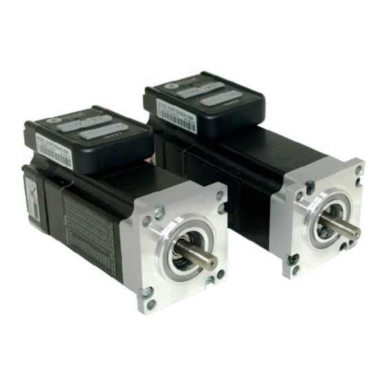
Page 4: Introduction To Integrated Servo Motor
Measured Position Applications Leadshine’s iSV-B23xxx can be used in various applications such as laser cutters, laser markers, high precision X-Y tables, labeling machines, CNC router, etc. Its unique features make the iSV-B23xxx an ideal choice for applications that require both low-speed smoothness and small mounting space. -
Page 5: Getting Start
Hardware installation manual of the integrated servo motor Getting Start To get start you need one integrated servo motor, one DC power supply and one motion controller. The motion controller such as indexer, pulse generator or PLC is only required when you need to rotate the motor. -
Page 6: Connecting Motion Controller
Hardware installation manual of the integrated servo motor + (Positive) +Vdc - (Negative) DC Power iSV-x23xxx DC power connection of ISV-B23xxx Connecting Motion Controller Pulse, Direction, Enable Input The pulse, direction and enable input of the iSV motor is differential. It can also be connected to PNP (sourcing) or NPN (sinking) type controller. - Page 7 Hardware installation manual of the integrated servo motor Pulse, Direction, Enable Input (Continued) In a PNP (sinking) type output, the control signals are refer to the same ground terminal. iSV-x23xxx Controller VCC = 5-24V 5V recommended Step PUL+ PUL- Direction DIR+ DIR- Enable...
-
Page 8: Alarm, In-Position Output
The ProTuner can be downloaded from our website: http://www.leadshine.com or you may also get it from Leadshine CD. It is recommended to get it from the website because it is always the latest. Install it on your PC and make it ready for use later. RS232 Cable... -
Page 9: Configuration
Hardware installation manual of the integrated servo motor connections! Configuration There are not much parameters need to be configured for the integrated servo motor. You can configure it by the DIP switch or PC software. Configuring iSV Motor by DIP Switches A 6-bit DIP switch which is on side of the drive case can be used to set the pulses/rev setting, motion direction and active of pulse. -
Page 10: Configuring Isv Motor In Pc Software
Hardware installation manual of the integrated servo motor Configuring ISV motor in PC Software Leadshine already loads default current-loop parameters and position-loop parameters. The default parameter values of the current loop have been optimized and there is no need to tune them. -
Page 11: Power Supply Selection
Hardware installation manual of the integrated servo motor for more information. Power Supply Selection To achieve good driving performances, it is important to choose a suitable supply voltage and use a matching current value. Generally speaking, supply voltage determines the high speed performance of the motor, while output current determines the output torque of the driven motor (particularly at lower speed). -
Page 12: Recommended Supply Voltage
Driver Lower Input limit Driver Input Voltage Driver Input Voltage Power Supply Voltage Power Supply Voltage Recommended Supply Voltage Both Leadshine’s regulated and unregulated power supply has been designed specially for motion control. Model Input Voltage Range Typical Voltage Leadshine Power Supply... -
Page 13: Control Signal Setup Timing
>2.5us / >1.0us Fine Tuning Leadshine already loads default current-loop parameters and position-loop parameters. The default parameter values of the current loop have been optimized and there is no need to tune them. However, you need to tune the position loop parameters for your application to achieve the best performance. -
Page 14: Protection Functions & Indications
Hardware installation manual of the integrated servo motor Protection Functions & indications To improve reliability, the IES incorporates some built-in protection functions. The Integrated stepper uses one red LED to indicate the protection type. The periodic time of red is 4 s (seconds), and the blinking times of red LED indicates what protection has been activated. -
Page 15: Over-Current Protection
Hardware installation manual of the integrated servo motor Protection Functions & indications (Continued) Over-current Protection Over-current protection will be activated when continuous current exceeds 18A or in case of short circuit between motor coils or between motor coil and ground, and RED LED will blink once within each periodic time. -
Page 16: Frequently Asked Questions
Hardware installation manual of the integrated servo motor Frequently Asked Questions In the event that your drive doesn’t operate properly, the first step is to identify whether the problem is electrical or mechanical in nature. The next step is to isolate the system component that is causing the problem. -
Page 17: Warranty
Leadshine Technology Co., Ltd. warrants its products against defects in materials and workmanship for a period of 12 months from shipment out of factory. During the warranty period, Leadshine will either, at its option, repair or replace products which proved to be defective. -
Page 18: Contact Us
Web: http://www.leadshine.com Sales Hot Line: Tel: 86-755-2641-7674 (for Asia, Australia, Africa areas) 86-755-2640-9254 (for Europe areas) 86-755-2641-7617 (for America areas) Fax: 86-755-2640-2718 Email: sales@leadshine.com. Technical Support: Tel: 86-755-2641-8447, 86-755-2641-8774, 86-755-2641-0546 Fax: 86-755-2640-2718 Email: tech@leadshine.com(for All) Leadshine U.S.A Address: 25 Mauchly, Suite 318 Irvine, California 92618...
Need help?
Do you have a question about the iSV-B23 Series and is the answer not in the manual?
Questions and answers