
Related Manuals for Nussbaum OTTO 18


Summary of Contents for Nussbaum OTTO 18
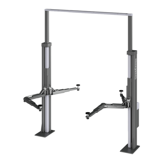
- Page 1 Operating manual | Inspection book including spare parts list Version: USA Manual date: 13.01.2020 POWER LIFT HDL 15000 POWER LIFT HDL 18000 Serial No. Made Germany...
- Page 2 OPI-POWER LIFT HDL 15000 - HDL 18000-V1.0-EN...
-
Page 3: Table Of Contents
General informations ........5 Installation ............37 Lift purpose ..............5 Operating manual ..........37 Liability ................ 5 Owner/Employer responsibilities ......5 Lifting the vehicle ........... 37 Lift operator responsibilities ........6 Lowering the vehicle ..........38 Safety regulations ............. 6 Travel measurement ..........38 Safety devices ............ -
Page 5: General Informations
National Standard for Automotive Lifts-Safety Requirement for Operation, Inspection and Main- Lift purpose tenance; ALI/WL Series, ALI Uniform Warning Label Nussbaum lifting systems are the result of over 35 Decals/Placards; and in case of frame engaging years’ experience in the automotive lifting industry. lifts, ALI/LP-GUIDE, Vehicle Lifting Points/Quick Refer-... -
Page 6: Lift Operator Responsibilities
• Shall not allow unauthorized personnel to operate • For unusual vehicles you may choose to instruct the Lift. the user to contact Nussbaum for lifting advice. • The main electrical switch must be switched off and locked out or tagged out according to OSHA... -
Page 7: Safety Devices
Save these instructions! Safety devices Nussbaum has designed several saftety features into each Lift to ensure safe and efficient opera- tions under a variety of conditions. Warranties will be voided and dangerous working conditions exist if any of the listed devices are altered or disabled. -
Page 8: Safety Labels Affixed To Lift
Automotive Lift Institute, Inc. WL101 Series Label Kit Safety labels affixed to lift NOTICE NOTICE Warning Label pictographs Read operating Proper maintenance and safety manuals and inspection used with permission of Auto- before using lift. is necessary for safe operation. motive Lift Institute. -
Page 9: Protocols
Read all labels and verify that all authorized users fully understand the meaning of each caution / warning / safety instruction. Do not remove or de- face safety labels from the lift. Protocols Technical documentation contains important infor- mation for safe operation and for retaining func- tional safety of the lift. -
Page 10: Set Up Protocol
After successful set up, complete this form fully, sign it, make a copy and send the original to the man- ufacturer within a week. The copy remains in the inspection book. Nussbaum Automotive Solutions, LP 1932 Jordache Court Gastonia, NC 28052 Fax: 1-704-864-2476 Email: warranty@nussbaum-usa.com... -
Page 11: Transfer Protocol
Transfer protocol The lift with serial number _________________________ was set up on (date) ______________________________ at (company name) _____________________________ in (town, city) _____________________________________ checked for function and safety and put into operation. The following listed people (operators) were trained to handle the lift after it was set up by a trained assem- bler of the manufacturer or a contract partner (specialist). -
Page 12: System Master Sheet
System master sheet Manufacturer Otto Nussbaum GmbH & Co. KG Korker Straße 24 D-77694 Kehl-Bodersweier Purpose The lift is a lifting tool for raising vehicles up to a total weight of 15000 lbs (7000 kg) or 18000 lbs (8000 kg) for normal workshop operation. -
Page 13: Technical Information
Technical information Safety devices • Over-pressure valve Hydraulic system fuse against over-pressure Technical data • Check valve Secure the vehicle against unauthorised lowering Load carrying capacity HDL 15000 = 15000 lbs • Lockable main switch (6500 kg) Fuse to prevent unauthorised use HDL 18000 = 18000 lbs •... -
Page 14: Data Sheets
Data sheets OPI-POWER LIFT HDL 15000 - HDL 18000-V1.0-EN... - Page 15 OPI-POWER LIFT HDL 15000 - HDL 18000-V1.0-EN...
- Page 16 Clearance around the lift recommended clearance above the lift, if there is no specification in the datasheet recommended clearance around the lift 2 0 " 2 0 " OPI-POWER LIFT HDL 15000 - HDL 18000-V1.0-EN...
-
Page 17: Hydraulic Plan / Per Lift Column
Hydraulic plan / per lift column 1 .1 WEP06DA 13B 0240S 1 .4 1 .2 30 bar 1 .6 1 .5 1 .3 Dr D1,3 1 .7 1 .0 V 0 0 SPX 240 POWER UNIT 162406 PRESSURE REDUCING VALVE 161060 PROPORTIONAL VALVE 99-540-11-00-5 BLOCK COMPLETE... -
Page 18: Pneumatic Plan
Pneumatic plan AIR PRESSURE 6–10 BAR 960049 COIL 960047 VALVE 265HDL28220 CYLINDER Stückliste: 0.1 Druckluftanschluss 6-10 bar air pressure 0.2 Pneumatikventil 960047 valve Spule 960049 coil 1.0 Zylinder kpl. 265HDL28220 cylinder 041214 V 01 Version Datum OPI-POWER LIFT HDL 15000 - HDL 18000-V1.0-EN... -
Page 19: Electrical Circuit Diagram
Electrical circuit diagram Grounding according to local regulations Before commissioning check whether the nominal motor current matches the motor protection relay. Check all terminal points for proper connection and that all contact screws are tight. Before commissioning, check all wiring and controls for proper function. - Page 20 OPI-POWER LIFT HDL 15000 - HDL 18000-V1.0-EN...
- Page 21 OPI-POWER LIFT HDL 15000 - HDL 18000-V1.0-EN...
- Page 22 OPI-POWER LIFT HDL 15000 - HDL 18000-V1.0-EN...
- Page 23 OPI-POWER LIFT HDL 15000 - HDL 18000-V1.0-EN...
- Page 24 OPI-POWER LIFT HDL 15000 - HDL 18000-V1.0-EN...
- Page 25 OPI-POWER LIFT HDL 15000 - HDL 18000-V1.0-EN...
- Page 26 OPI-POWER LIFT HDL 15000 - HDL 18000-V1.0-EN...
- Page 27 ...
- Page 28 ...
- Page 29 ...
- Page 30 ...
- Page 31 OPI-POWER LIFT HDL 15000 - HDL 18000-V1.0-EN...
- Page 32 OPI-POWER LIFT HDL 15000 - HDL 18000-V1.0-EN...
- Page 33 OPI-POWER LIFT HDL 15000 - HDL 18000-V1.0-EN...
- Page 34 OPI-POWER LIFT HDL 15000 - HDL 18000-V1.0-EN...
- Page 35 OPI-POWER LIFT HDL 15000 - HDL 18000-V1.0-EN...
- Page 36 OPI-POWER LIFT HDL 15000 - HDL 18000-V1.0-EN...
-
Page 37: Installation
Installation to consult a qualified person to address any local or state requirements (per the ALCTV standard: “a The installation of the Lift is performed by manufactur- qualified person should be consulted to address er trained technicians or by the manufacturer’s distri- any seismic loads and other local or state require- bution partner. -
Page 38: Lowering The Vehicle
• Switch on controls. Turn the main switch to posi- • Place the vehicle to the desired work position or tion “1” lower it to the lowest position. • Lift the vehicle until the wheels are off the ground. Push the “Lower” button. The lift raises briefly (un- Push the “Lift”... - Page 39 5.4.1 Axle controller ASC2010 Settings Jumper settings 31 32 OPI-POWER LIFT HDL 15000 - HDL 18000-V1.0-EN...
- Page 40 LED OUT 1 X1100 DISPLAY CONNECTOR LED OUT 2 GREEN LED: CPU STATUS (FLASHES) LED OUT 3 P1101 POTENTIOMETER CONTRAST DISPLAY LED OUT 4 X501 ZERO JUMPER PIC 2 LED RED ENCODER AXIS 1 LED GREEN 5 V 2 LED RED ENCODER AXIS 2 LED GREEN 3.3 V 2 LED RED ENCODER AXIS 3 RED LED: IN 1...
-
Page 41: Behaviour In Cases Of Error
Power supply interrupt- Inform customer service The meaning of the switch is determined in the pro- gram, i.e. it has no application-specific functions. Thermal fuse of the mo- Let the water cool Normal HB: tor is active • Dip switch 5 – Automatic Controlled operation (only for trained persons!): Lift rails are uneven by Manual equalisation see more than 40 mm... -
Page 42: Moving Onto An Obstacle
Problem: The lift arms cannot be swivelled in or • Push the “▲” button until the obstacle can be re- out. moved. • The lift rail that is higher must be lowered with the possible causes: Repair: help of the dip switch, (see Section “5.4”) The lift rails first move to unlock up- The unlock switch is not Have the button wards. - Page 43 Do an emergency discharge • Switch off the main switch and secure against re- start (shut down). • Loosen and remove all unit covers. • For safety reasons, block off the endangered area and the lift leaving ample room. • Loosen and remove 2 counter nuts (spanner width 41) at the upper end of the lift rails in the di- rection of the arrow.
-
Page 44: Reset After An Emergency Discharge
Reset after an emergency discharge A reset may only be done once the lift is in its lowest position. Access to the DIP switch may only be done by a trained, authorised spe- cialist. a) There may not be any vehicles on the lift. b) Remove the rear column covers on the operat- ing column. -
Page 45: Maintenance Plan
Maintenance plan Before beginning service, disconnect from power. The work area around the lift is to be secured against unauthorised use. Visual Spray Lubricate Clean with Clean Inspect inspection compressed Time frame Position Maintenance plan Person in Type of charge maintenance Lift owner / The lift cylinder can sweat and small oil droplets can... - Page 46 Time frame Position Maintenance plan Person in Type of charge maintenance Lifting arm booms, lifting arm bolts, carrier plate Trained ser- threaded bolts are to be checked for ease of running. 1 x / 12 vice personnel If required, lightly grease with multi-purpose grease. Do not over-lubricate.
- Page 47 Time frame Position Maintenance plan Person in Type of charge maintenance All weld seams must have a visual inspection. Stop Trained ser- 1 x / 12 the system and contact the manufacturer if there are vice personnel cracks or breaks in weld seams of the lift. Check electrical components for function and con- dition.
- Page 48 Time frame Position Maintenance plan Person in Type of charge maintenance According to manufacturer instructions, the hydraulic oil should be changed every two years in normal op- erations. Various environmental influences e.g. loca- tion, temperature swings, intensive operation etc, can have an influence on the quality of the hydraulic oil.
- Page 49 Time frame Position Maintenance plan Person in Type of charge maintenance Hydraulic hose lines Storage and duration of use Excerpt from DIN20066:2002-10 • For permitted loading, hoses undergo a natural change. This limits the duration of use. • Improper storage, mechanical damage and unper- mitted loads are the most frequent cause of break- downs.
-
Page 50: Cleaning The Lift
Cleaning the lift secured on-site with 16 ampere fuses. The con- A regular and expert clean helps retain the value nection point is located on the operating boxes. of the lift. • To protect the electrical cable all cable conduits Additionally, it can also be a pre-requisite for the are to be fitted with cable sleeves or flexible plas- preservation of guarantee claims for any eventual tic pipes. -
Page 51: Commissioning
• Tighten the anchor to the required torque (see Before re-commissioning, a safety inspection the conditions of the anchor manufacturer). must be done by a specialist (use the regular safety inspection form) Each anchor must be tightened to the required torque. - Page 52 8.3.1 Selection the Liebig anchor without floor cover (2.65 HDL SST, 2.70 HDL SST, 2.80 HDL SST) Liebig anchor Anchor type BM16-25/100/40 Drill depth (mm) Min. anchoring depth (mm) Concrete thickness (mm) min. 200* Drill diameter (mm) Drilled part thickness (mm) 0 –...
- Page 53 8.3.2 Selection the Liebig anchor with floor cover (2.65 HDL SST, 2.70 HDL SST, 2.80 HDL SST) Liebig anchor Anchor type BM16-25/100/65 BM16-25/100/100 Drill depth (mm) Min. anchoring depth (mm) Concrete thickness (mm) min. 200* min. 200* Drill diameter (mm) Component thickness (mm) e + f 40 –...
- Page 54 8.3.3 Fischer anchor Marking the anchoring depth subject to alterations! fischer anchor 2.65 HDL SST 2.70 HDL SST 2.80 HDL SST typ of dowel FH 24/100 B Order No. 970267 drilling depth (mm) min.anchorage depth (mm) thickness of concrete (mm) see current founda- tion-diagram draw- diameter of bore (mm)
- Page 55 8.3.4 Hilti injection anchor (2.65 HDL SST, 2.70 HDL SST, 2.80 HDL SST) Quality of concrete Normal armouring subject to alterations! Adhesive and anchor rod: HIT-HY 200-A + HIT-V (5.8) M16 Art. Hilti: 387066 HIT-V-5.8 M16x300 / 2022696 Seismic / filling set or suitable filling method Effective anchoring depth: = 190.0 mm Material:...
-
Page 56: Safety Inspection
Safety inspection The safety inspection is required to guarantee oper- ational safety of the lift. It is to be done: 1. before first commissioning after setting up the lift Use the “single safety inspection” form 2. After first commissioning, check regularly at least once per year. Use the “regular safety inspection” form 3. After changes to the lift construction. Use the “extraordinary safety inspection” form Single and regular safety inspections must be done by a specialist. -
Page 57: Single Safety Inspection Before Commissioning
Single safety inspection before commissioning Copy, Complete and leave in the inspection book Serial number: _______________________________ Test step Defect Retest Remarks Missing □ □ □ General condition of lift .............._______________________________ □ □ □ Model plate .................. -
Page 58: Regular Safety Inspection And Maintenance
Regular safety inspection and maintenance Copy, Complete and leave in the inspection book Serial number: _______________________________ Test step Defect Retest Remarks Missing □ □ □ General condition of lift .............._______________________________ □ □ □ Model plate .................. - Page 59 Regular safety inspection and maintenance Copy, Complete and leave in the inspection book Serial number: _______________________________ Test step Defect Retest Remarks Missing □ □ □ General condition of lift .............._______________________________ □ □ □ Model plate ..................
- Page 60 Regular safety inspection and maintenance Copy, Complete and leave in the inspection book Serial number: _______________________________ Test step Defect Retest Remarks Missing □ □ □ General condition of lift .............._______________________________ □ □ □ Model plate ..................
- Page 61 Regular safety inspection and maintenance Copy, Complete and leave in the inspection book Serial number: _______________________________ Test step Defect Retest Remarks Missing □ □ □ General condition of lift .............._______________________________ □ □ □ Model plate ..................
- Page 62 Regular safety inspection and maintenance Copy, Complete and leave in the inspection book Serial number: _______________________________ Test step Defect Retest Remarks Missing □ □ □ General condition of lift .............._______________________________ □ □ □ Model plate ..................
- Page 63 Regular safety inspection and maintenance Copy, Complete and leave in the inspection book Serial number: _______________________________ Test step Defect Retest Remarks Missing □ □ □ General condition of lift .............._______________________________ □ □ □ Model plate ..................
- Page 64 Regular safety inspection and maintenance Copy, Complete and leave in the inspection book Serial number: _______________________________ Test step Defect Retest Remarks Missing □ □ □ General condition of lift .............._______________________________ □ □ □ Model plate ..................
- Page 65 Regular safety inspection and maintenance Copy, Complete and leave in the inspection book Serial number: _______________________________ Test step Defect Retest Remarks Missing □ □ □ General condition of lift .............._______________________________ □ □ □ Model plate ..................
- Page 66 Regular safety inspection and maintenance Copy, Complete and leave in the inspection book Serial number: _______________________________ Test step Defect Retest Remarks Missing □ □ □ General condition of lift .............._______________________________ □ □ □ Model plate ..................
- Page 67 Regular safety inspection and maintenance Copy, Complete and leave in the inspection book Serial number: _______________________________ Test step Defect Retest Remarks Missing □ □ □ General condition of lift .............._______________________________ □ □ □ Model plate ..................
-
Page 68: Exceptional Safety Inspection
Exceptional safety inspection Copy, Complete and leave in the inspection book Serial number: _______________________________ Test step Defect Retest Remarks Missing □ □ □ General condition of lift .............._______________________________ □ □ □ Model plate .................._______________________________ □... - Page 71 Spare parts list POWER LIFT HDL 15000 POWER LIFT HDL 18000 Made Made Germany Germany...
- Page 72 Column complete 265HDL05501_2 12.08.19 265HDL01758_BG DOWNPIPE 18 ELEKTROKASTEN 265HDL02050 PIPE 19 265HDL02712 ADAPTER PLATE 265HDL02053 20 265HDL05219 MOUNTING PANEL 265HDL05503 LIFTING COLUMN 21 265HDL01766 BLOCK COVER 265HDL26400 LIFT RAILS WITH LIFTING ARMS 22 265HDL05218 POWER CHAIN GUIDE 265HDL01750 ASSEMBLY UNIT BLOCK 23 ZS15_01_L10RB3_8 STRAIGHT SCREW IN FITTING 265HDL01755_BG P-PIPE TO THE UNIT 24 175RGK05074...
- Page 73 Cylinder assy. 265HDL22000_1 27.03.2004 OPI-POWER LIFT HDL 15000 - HDL 18000-V1.0-EN...
- Page 74 SPX Unit USA OPI-POWER LIFT HDL 15000 - HDL 18000-V1.0-EN...
- Page 75 Block Mounting Assembly 265HDL01750_1 01.07.19 1 99-540-11-00-5 CONTROL BLOCK 4 93901-L10A-G4_4 SUPPORTS WHEEL GRIPPER 5 265HDL01754 BLOCK HOLDER 2 91125_1-A8_4 WASHER 6 9933M8X12ZN HEXAGONAL SCREW 3 93901-L8A-G1_4 STRAIGHT SCREW-IN SOCKET 7 93901-L06-G1_4 SUPPORTS OPI-POWER LIFT HDL 15000 - HDL 18000-V1.0-EN...
- Page 76 Lift rails with lifting arms 265HDL26400 17.10.1996 265HDL06413 SCREW ON PLATE 265HDL06442 SPACER BAR 265HDL06403 LIFT RAILS RO12X1K5X400 CABLE PIPE 250TSAPH28000 LIFTING ARM FIXTURE LR211KDDUAH09 ROLLER COMPLETE LR5307KDD ROLLER RO12X1K5X52 - 9125_1-A5_3 WASHER 9S933M24X80 9S933M24X80 250TSAPH08126 HOSE COVER 265HDL06432 COVER 265HDL06445 U-PROFILE 265HDL06436 FASTENING BRACKET 9912-M5X20...
- Page 77 Hood 265HDL01032 15.03.2004 OPI-POWER LIFT HDL 15000 - HDL 18000-V1.0-EN...
- Page 78 Lifting arm fixture complete 250TSAPH28000_1 24.07.2003 250TSAPH28079 BOLTS ASSY. 250TSAPH08084 BOLT RETAINER 250TSAPH28001 LIFTING ARM 250TSAPH08104 LIFTING ARM FIXTURE COMPLETE 250TSAPH28002 LIFTING ARM 250TSAPH08088 TOOTHED LOCK WASHER 9912-M5X30 CYLINDER SCREW OPI-POWER LIFT HDL 15000 - HDL 18000-V1.0-EN...
- Page 79 Lifting arm fixture complete 280HDL08000_1 08.06.2005 280HDL08079 BOLTS ASSY. 250TSAPH08084 BOLT RETAINER 280HDL08001 LIFTING ARM 1 280HDL08094 LIFTING ARM FIXTURE COMPLETE 280HDL08002 LIFTING ARM 2 250TSAPH08088 TOOTHED LOCK WASHER 1 OPI-POWER LIFT HDL 15000 - HDL 18000-V1.0-EN...
- Page 80 Dealer address/phone: Nussbaum Automotive Solutions, LP • 1932 Jordache Court • Gastonia, NC 28052 www.nussbaum-usa.com • E-Mail: warranty@nussbaum-usa.com Fax: 1-704-864-2476 Service Hotline International: +49 180-5 288 911 OPI-POWER LIFT HDL 15000 - HDL 18000-V1.0-EN_012020 - Artikelnummer: 975539...
Need help?
Do you have a question about the OTTO 18 and is the answer not in the manual?
Questions and answers