Table of Contents
Advertisement
DIN A4: 7.10003.32.00
©
KROHNE 12/2002
US size: 7.10003.72.00
GR
How to use these Instructions
The flowmeters are supplied ready for operation.
The primary head must be installed in the pipeline as described in the installation
instructions inside the packing of the primary head.
–
Installation location and connection to power (Section 1)
–
Electrical connection of outputs and inputs (Section 2)
–
Factory settings and start-up (Section 3)
Power the flowmeter. THAT'S ALL. The system is operative.
Installation and
operating instructions
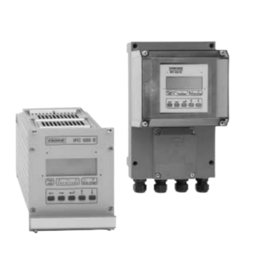
IFC 020 K
IFC 020 F
IFC 020 E
Signal converters for
electromagnetic flowmeters
Applicable to
Software Versions
G IFC 020 K and
G IFC 020 E
Pages 1/1-1/8
Pages 2/1-2/4
Pages 3/1-3/2
IFC 020 F
No. 3170330200
No. 3175870200
Variable area flowmeters
Vortex flowmeters
Flow controllers
Electromagnetic flowmeters
Ultrasonic flowmeters
Mass flowmeters
Level measuring instruments
Communications technology
Engineering systems & solutions
Switches, counters, displays and recorders
Heat metering
Pressure and temperature
Advertisement
Table of Contents

Related Manuals for KROHNE IFC 020 K


Summary of Contents for KROHNE IFC 020 K
- Page 1 IFC 020 K IFC 020 F IFC 020 E Signal converters for electromagnetic flowmeters Applicable to Software Versions G IFC 020 K and IFC 020 F No. 3170330200 G IFC 020 E No. 3175870200 Variable area flowmeters Vortex flowmeters Flow controllers...
-
Page 2: Table Of Contents
Factory settings Setting data Part B IFC 020 / D Signal converter 4/1-5/12 Operation of the signal converter 4/1-4/12 Krohne operator control concept Operating and check elements Function of keys 4/3-4/4 Table of settable functions 4/5-4/9 Error messages in measuring mode... - Page 3 Cleaning the signal converter housing Turning the converter housing of the compact flowmeters IFC 020 K and F: Directions for folding the ribbon cable on the display unit IFC 020 K and F: Illustrations of the PCBs IFC 020 E: Illustrations of the PCBs...
-
Page 4: Items Included With Supply
(standard: signal cable A, length 10 m / 30 ft) Software history Display & control unit Handheld HHT 020 CONFIG user software IFC 020 K and F IFC 020 E ImoCom, RS 485, HART Software Status... -
Page 5: System Description
In addition, the “General conditions of sale” forming the basis of the purchase contract are applicable. If flowmeters need to be returned to Krohne, please note the information given on the last-but-one page of these Instructions. Krohne regrets that it cannot repair or check your flowmeter(s) unless accompanied by the completed form sheet. -
Page 6: Part A System Installation And Start-Up
Refer to Sect. 1.3.4 for maximum permissible length of signal and field current cables. • Use the supplied Krohne signal cable A (Type DS), standard length 10 m (33 ft). • Always calibrate primary head and signal converter together. Therefore, when installing, ensure primary constant GK is identical;... -
Page 7: Connection To Power
Connection to power PLEASE NOTE ! • Rated values: The flowmeter housings protecting the electronic equipment from dust and moisture must always be kept closed. The selected creepage distances and clearances have been dimensioned in conformity with VDE 0110 and IEC 664 for contamination category 2. -
Page 8: Electrical Connection Of Separate Primary Head (F- And E Versions)
Electrical connection of separate primary heads (F- and E- versions) 1.3.1 General remarks on signal lines A and B and field current line C Proper operation of the equipment is ensured when Krohne signal lines A and B are used with foil screen and magnetic shield. -
Page 9: Stripping (Preparation) Of Signal Cable A And B 1.3.3
Stripping (preparation) of signal cable A and B 1.3.3 Please note the different lengths given in the table for signal converter and primary head. Customer-supplied materials Length Converter Primary W Insulation tubing (PVC), Ø 2.0 - 2.5 mm (dia. 1”) IFC 020 F + E only IFC 020 E head... - Page 10 1.3.4 Cable lengths (max. distance between signal converter and primary head) Abbreviations and explanatory notes used in the following tables, diagrams and connection diagrams A Signal cable A (type DS), with double shielding, see diagram A for max. length B Signal line B (type BTS) with triple shielding, max. length see diagram B (IFC 020 E only) C Field current cable min.
-
Page 11: Connection Diagrams I And Ii (Ifc 020 F Signal Converter And Primary Head)
Connection diagrams I and II (IFC 020 F signal converter and primary head) 1.3.5 Important information on connection diagrams PLEASE NOTE! • The figures in brackets indicate the stranded drain wires for the shields, see cross-sectional drawing of signal cable in Section 1.3.1. •... -
Page 12: Connection Diagrams Iii And Iv (Ifc 020 E Signal Converter And Primary Head)
1.3.6 Connection diagrams III to VI (IFC 020 E signal converter and primary head) Important information on connection diagrams PLEASE NOTE! • The figures in brackets indicate the stranded drain wires for the shields (see cross-sectional drawing of signal cable in Section 1.3.1). •... - Page 13 Process temperature > 150 °C (302 °F) Signal cable A (type DS) Signal cable B (type BTS) IFC 020 E IFC 020 E 24 V DC 0L = 1L = 24 V DC 0L = 1L = Primary head Primary head Installation and operating instructions IFC 020...
-
Page 14: Electrical Connection Of Outputs And Inputs
Electrical connection of outputs and inputs Current output I • The current output is galvanically isolated from all input and output circuits. • Factory-set data and functions can be noted down in Sect. 5.16. Please also refer to Sect. 3.2 “Factory settings”. I+ approx. - Page 15 • Characteristics of the status outputs Switch open Switch closed OFF (switched off) without function ON (e.g. operation indicator) Power supply OFF Power supply ON F/R INDICATOR (F/R mode) Forward flow Reverse flow TRIP POINT (Limit switch) Inactive Active ALL ERRORS (all errors) Errors No errors FATAL ERRORS (fatal errors only)
- Page 16 IFC 020 E separated, 19” plug-in unit, connection cap X2 IFC 020 F separated, field housing Milliammeter 0 or 4-20mA and others IFC 020 K compact Key, N/O contact External voltage source (U DC or AC voltage, connection polarity arbitrary...
-
Page 17: Control Input E (Applicable With Ifc 020 E Only)
Control input E RS 485 Interface passive (IFC 020 E only) For connection and operation of the Krohne RS 485 ≤ 30 V DC/≤ 24 V AC Interface, ≤ 6 mA see Section 6.2. Installation and operating instructions IFC 020... -
Page 18: Start-Up
Start-up Power- on and measurement • Before powering the system, please check that it has been correctly installed according to Sect. 1 and 2. • The flowmeter is delivered ready for operational use. All operating data have been factory set in accordance with your specifications. Please refer to Sect. -
Page 19: Setting Data
→ → → ↵ ↵ ↵ ↑ ↑ ↑ 3.05 User-defined unit 3.06 Application Flow is - steady - pulsating 3.07 Measuring point 3.08 Communication interface o Off o HART o KROHNE RS 485 Address Baud rate Installation and operating instructions IFC 020... -
Page 20: Operation Of The Signal Converter
IFC 020 _ / D Signal converter Teil B Operation of the signal converter Krohne operator control concept Measuring mode 1 3 6. 4 9 m 3 / h r → When this display appears, press following keys: CodE 1 →... -
Page 21: Operating And Check Elements
Operating and check elements IFC 020 The controls are accessible after unscrewing the 4 screws and removing the housing cover. • Display, 1st line ‚ Display, 2nd line ƒ Display, 3rd line: arrows to identify display Flowrate current flowrate Totalizer totalizer –... -
Page 22: Function Of Keys
Function of keys The cursor (flashing part of display) has a grey background in the following descriptions. To start operator control Operator control mode Measuring mode → 1 3 . 5 7 1 F c t . 1. 0 0 m 3 / h r O P E R A T I O N PLEASE NOTE: When “YES”... - Page 23 To change numbers increase number ↑ 3 9 7. 3 5 3 9 7. 4 5 ↓ m 3 / h r m 3 / h r decrease number To shift cursor (flashing position) shift to right → 3 9 7. 3 5 3 9 7.
-
Page 24: Table Of Settable Functions
Table of settable functions Abbreviations used actual flowrate Control input (IFC 020 E only) 100% flow = full scale range Nominal size, meter size 100% Highest frequency of pulse output π / max. full-scale range (Q Lowest frequency of pulse output 100% at v = 12 m/s / 40 ft/s... - Page 25 Fct. Text Description and settings 1.04 DISPLAY Display functions → DISP.FLOW Select flow display • NO DISP. • user unit, factory set is “Liter/hr” or “US MGal/day (see Fct. 3.05) • m3/hr • PERCENT • Liter/Sec • BARGRAPH (value and bargraph display in %) •...
- Page 26 Fct. Text Description and settings 1.06 PULS B1 Pulse output P → FUNCT. P Select function for pulse output P • OFF (switched off) • 1 DIR. (1 flow direction) • 2 DIR. (forward/reverse flow, F/R flow measurement) Press key ↵ to transfer to subfunction “SELECT P”. →...
- Page 27 Fct. Text Description and settings 3.00 INSTALL. Installation menu 3.01 LANGUAGE Select language for display texts • GB / USA (English) • F (French) • D (German) • others on request Press ↵ key to return to Fct. 3.01 “LANGUAGE”. 3.02 FLOWMETER Set data for primary head...
- Page 28 Press ↵ key to return to Fct. 3.07 ”MEASURING POINT” 3.08 Set comminucation interface • OFF (switched off) • HART (HART-interface switched on) • KROHNE (RS 485 interface switched on) • Address:”HART” 00-15 / “KROHNE” 000-239 • BAUD RATE: -1200 -2400 -4800...
-
Page 29: Error Messages In Measuring Mode
Error messages in measuring mode The following list gives all errors that can occur during process flow measurement. Errors shown in display when “YES“ set in Fct. 1.04 DISPLAY, subfunction “DISP. MSG.“. Error messages Description of error Error clearance LINE INT. Power failure Note: Cancel error in RESET/QUIT. -
Page 30: Reset Totalizer And Cancel Error Messages, Reset/Quit Menu
Reset totalizer and cancel error messages, RESET / QUIT menu Cancel error messages in RESET / QUIT menu Display Description - - - - - - - - - - - - / - - - Measuring mode ↵ CodE 2 Key in entry code 2 for RESET / QUIT menu: ↑... -
Page 31: Examples Of Setting The Signal Converter
Examples of setting the signal converter As an example the cursor, flashing part of display, is shown below in bold type. • Change measuring range of current output and value for error messages (Fct. 1.05): • Change measuring range from 04-20 mA to 00 -20 mA •... -
Page 32: Description Of Functions
Description of functions Full-scale range Q 100% Fct. 1.01 FULL SCALE Press → key. Choice of unit for full-scale range Q 100% • m3/hr (cubic metres per hour) • Liter/Sec (litres per second) • US.Gal/min (US gallons per minute) • User-defined unit, factory-set is „Liter/hr“... -
Page 33: Display
Low-flow cutoff Fct. 1.03 L.F.CUTOFF Press → key. Choice • (fixed tripping point: ON = 0.1 % / OFF = 0.2 % with 100Hz and 1000Hz, see Fct. 1.06; 1% resp. 2%) • PERCENT (variable tripping points: ON = 1 - 19 % / OFF = 2 - 20 %) Select with ↑... -
Page 34: Internal Electronic Totalizer
Setting of totalizer format • Auto (exponent notation) • # . ####### • ##### . ### • ## . ###### • ###### . ## • ### . ##### • ####### . # • #### . #### • ######## Select with ↑ or ↓ key.. Press ↵... -
Page 35: Current Output I
Current output I Fct. 1.05 CURRENT I Press → key. → FUNCT. I = Select function for current output, press → key • (switched off, no function) • 1 DIR. (1 flow direction) • 2 DIR. (2 flow directions, F/R mode, forward/reverse) Select using ↑... -
Page 36: 5.7 Pulse Output P
5.7 Pulse output P Fct. 1.06 PULS.OUTP. P Press key → . → FUNCT. P = select function for pulse output, press → key • (switched off, no function) • 1 DIR. (1 flow direction) • 2 DIR. (2 flow directions, F/R mode, forward/reverse) Select with key ↑... - Page 37 → VALUE P = set pulse value per unit volume (appears only when “PULSE/VOL.” set under “SELECT P”, press → key. • XXXX PulS/m3 • XXXX PulS/Liter • XXXX PulS/US.Gal • XXXX PulS/ user unit, factory-set: “Liter” or “US MGal”, see Sect. 5.12. Select using ↑...
-
Page 38: Status Output S
Status output S Fct. 1.07 STATUS S Press key → . Select function of status outputs, press → key • ALL ERROR (indicates all errors) • FATAL.ERROR (indicates fatal errors only) • (switched off, no function) • (indicates that flowmeter is operative) •... -
Page 39: Language
Language Fct. 3.01 LANGUAGE Press → key. Select language for texts in display • (German) • GB/USA (English) • (French) • others on request Select using ↑ or ↓ key. Press ↵ key to return to Fct. 3.01 LANGUAGE. Entry code 5.10 Fct. -
Page 40: Primary Head
5.11 Primary head Fct. 3.02 FLOW METER Press → key. → DIAMETER = set meter size (see instrument nameplate) press → key Select size from table of meter sizes: • DN 2.5 - 1000 mm equivalent to - 40 inch Select using ↑... -
Page 41: User-Defined Unit
User-defined unit 5.12 Fct. 3.05 USER UNIT Press → key. → TEXT VOL = set text for user-defined unit, press → key • Liter (max. 5 characters, factory-set: “Liter” or “US MGal”) Characters assignable to each place: A-Z, a-z, 0-9, or “–” (= blank character) Change flashing place (cursor) using ↑... -
Page 42: F/R Mode, Forward/Reverse Flow Measurement
5.13 F/R mode, forward/reverse flow measurement • Refer to Sect. 2.4 for electrical connection of outputs. • Define direction of forward (normal) flow, see Fct. 3.02, subfunction “FLOW DIR.”: in conjunction with F/R operation, set the direction for the forward flow here. “+”... - Page 43 Press key ↵ dto return to Fct. 3.08 COM. Use key ↑ or ↓ to set ADDRESS 000-239 after selecting "KROHNE" (RS 485). Press key → and set up BAUD RATE: • 1200 • 2400 • 4800 • 9600 • 19200. Use key ↑ or ↓ to select baud rate.
- Page 44 The following HART features are supported: • point-to-point connection • multidrop (up to 15 HART devices) The burst mode is not normally used. Further information about HART is available from the HART Communication Foundation, of which Krohne is a member. Electrical connection ® ®...
- Page 45 S6 and S7 on the amplifier PCB. For further information refer to sections 8.8 and 8.9. The RS 485 protocol is available. Please contact your local Krohne supplier / company. Settings for use in interface operation Fct.
- Page 46 - Homogeneous liquid products, free of solids and gasses an do not tend to electrical or catalytic reactions. IFC 020 K and IFC 020 F Changes on amplifier PCB, see Fig. in Sect. 8.8. Switch off power source before opening the housing! Fig.
- Page 47 IFC 020 E Changes on amplifier PCB, see Fig. in Sect. 8.9. Switch off power source before opening the housing! Illustrations 1 till 3 are situated in Section 8.1 Unscrew the 4 recessed head screws (S1) on the front side (Fig. 1). Carefully remove the plug-in unit from the subassembly support.
- Page 48 6.4 Pulsating flow Application downstream of positive-displacement pumps (reciprocating or diaphragm pumps) without pulsation dampener Operator control of the signal converter for the new settings, see Sect. 4 and 5 To change settings • Fct. 3.02 FIELD FREQ. (change magnetic field frequency) –...
- Page 49 Unsteady display and outputs Unsteady display and outputs can occur in connection with – high solids contents, – non-homogeneity, – poor blending, or – chemical reactions still in progress in the process liquid. If, in addition, flow is also pulsating due to the use of diaphragm or reciprocating pumps, refer to Sect.
- Page 50 Functional checks Zero check Fct. 3.03 Switch off power supply before opening the housing • Set “zero” flow in the pipeline, but make sure that the measuring tube is completely filled with fluid. • Switch on the system and wait 15 minutes. •...
- Page 51 - - - - - / - - - Measuring mode If you need to return your flowmeter to Krohne, please refer to last but one page of these Instructions ! Faults and symptons during start-up and process flow measurement •...
- Page 52 Test ok, check connection cables and receiver instrument, replace if necessary. Test faulty, current output defective. Replace signal converter (see Sect. 8.4) or contact Krohne Service Current output disabled, Activate under Fct. 1.05. see Fct. 1.05 Short-circuit between current Check connection and cables, output and pulse output.
- Page 53 Test faulty, pulse output defective, replace signal converter (see Sect. 8.4) or contact Krohne Service. Current output is external Check connection and cables, voltage source, short circuit see Sect. 2.4. Voltage between I + and I⊥ approx. 15 V.
- Page 54 IFC 020K and IFC 020 F Electrical connection Using GS 8 simulator Additional adapter is required between GS 8 and IFC 020 K and IFC 020 F signal converter. Order No. 2.10764.00. Outputs U-clamp terminal Power I⊥...
- Page 55 Potentiometer "zero point" Switch, Measuring ranges Electrical connection Leitung zwischen GS 8A und IFC 020 K und IFC 020 F Meßumformer Electrical connection of IFC 020 E and GS 8A Electrical connection of mA meter and electronic frequency counter (see Sect. 2.4).
- Page 56 7.5.3 Check of setpoint display Switch on power supply, allow at least 15 minutes’ warm-up time. Set switch D (front panel of GS 8A) to “0” position. Adjust zero to 0 or 4 mA with the 10-turn potentiometer P (front panel of GS 8A), depending on setting in Fct.
- Page 57 61.905 Deviations are permissible between 127.3 and 131.1 pulses/hr (equivalent to ± 1.5 %). If you need to return your flowmeter to Krohne, please refer to last but one page of these Instructions ! Installation and operating instructions IFC 020...
- Page 58 Service Illustrations used for service work IFC 020 K IFC 020 F Switch off power supply before starting service work! Fig. G Fig. A Fig. D Fig. B Fig. E Fig. C Fig. F Installation and operating instructions IFC 020...
- Page 59 IFC 020 E Switch off power supply before starting service work! Fig. 1 Fig. 2 Front plate / Display Fig. 3 Socket on display PCB Ribbon cable Locking clip of socket B Installation and operating instructions IFC 020...
- Page 60 Reassemble in reverse order, points 2) – 1) above. Power PCB Power supply Fuse F1 IFC 020 K and IFC 020 F for Section 8.3 Location and position of voltage selector Rating Order No. 1. AC version 230/240 V AC 125 mA T 5.06627...
- Page 61 8.3. Switch off power source before opening the housing ! IFC 020 E IFC 020 K and IFC 020 F Refer to Sect. 8.1 for Figs. A to F. Refer to Sect. 8.1 for Figs. 1 to 3. Unscrew the 4 recessed head screws Unscrew the 4 screws (S1), (Fig.
- Page 62 Replacement of electronics unit of signal converter Switch off power source before opening the housing ! IFC 020 E IFC 020 K and IFC 020 F Refer to Sect. 8.1 for Figs. A to G. Refer to Sect. 8.1 for Figs. 1 to 3.
- Page 63 IFC 020 K and IFC 020 F: Turning the display PCB Switch off power supply before opening the housing! r the illustrations A, B and D refer to Section 8.1. 1) Unscrew the 4 recessed head screws (Fig. A), and remove transparent cover from signal converter housing 2) Unscrew recessed head screw (Fig.
- Page 64 IFC 020 K and IFC 020 F: Directions for folding the ribbon cable on the display unit Version 2 Socket X7 on amplifier PCB, see Sect. 8.8 Socket on display PCB Contact side Display Ribbon cable Insulated side 5 keys for operator control Reference point, power terminals 90°...
- Page 65 IFC 020 K and IFC 020 F: Illustrations of the PCBs A) Amplifier PCB IC 13 DATAPROM (sensor), see Sect. 8.4. S1, S3 for “empty tube” cut-out, see Sect. 6.3. S2, S4 not used S6, S7 for blanking off the bus...
- Page 66 See Section 8.4 S2, S3 For use of empty tube cut-off See Section 6.3 Not used S6, S7 Used to blank off electrical bus of Krohne RS 485 Interface See Section 6.2 IC 13 Power supply PCB, AC Versions Voltage selector...
- Page 67 Order-numbers Electronic unit Power supply unit Power supply Order No. IFC 020 K IFC 020 E IFC 020 F AC Version 1 230 / 240 V AC 2.10989.01 2.11502.02 115 / 117 V AC AC Version 2 200 V AC 100 V AC 2.10989.02...
- Page 68 Part D Technical Data, Measuring Principle and Block Diagram Technical data 10.1 Full-scale range Q 100% Full-scale ranges Q 100% Flow rate Q = 100 % 6 liter/h to 33 900 m /h (0.03 - 156 000 US Gal/min), adjustable as required, equivalent flow velocity 0.3 - 12 m/s (1 - 40 ft/s) Unit /hr, Liter/Sec, US gallons/min.
- Page 69 6 and 7 (1) All Krohne signal converters undergo burn-in tests, duration minimum 20 hours at varying ambient temperatures – 20 to + 60°C/– 4 to + 140°F. The tests are controlled by computers.
- Page 70 10.3 IFC 020 signal converter Versions with display / control elements HART and RS 485 interfaces ® IFC 020 K Compact version,converter directly mounted on the signal converter version IFC 020 F Seperate housing fieldversion IFC 020 E Seperate housing, 19” Plug-in unit...
- Page 71 When connected to functional extra-low voltage, galvanic, safety separation (PELV) is essential (to VDE 0100/VDE 0106 and IEC 364/IEC 536 or equivalent national standard). Housing IFC 020 K / IFC 020 F Materials Polyamid (PA) and die-cast aluminium Protection category (IEC 529/EN 60 529)
- Page 72 10.4 IFC 020 and ZD dimensions and weights IFC 020 F ZD Intermediate weight approx. 3.8 kg / 8.4 lb connection box Weight approx. 160 (6.30”) 0.5 kg/1.1 lbs 144 (5.67”) dia. 9 (0.35”) 68 (2.68”) 125 (4.92”) PG 16 ”...
- Page 73 IFC 020 E Dimensions (in mm) Weight approx. 1.4 kg Subassembly support 3 HE, assembly dimensions in compliance with DIN 41491, Part 5 F-shaped multipole connector, DIN 41612 Guiding rails Front plate thread bore hole 1 TE = 05.08 mm (M 2.5) 1 HE = 44.17 mm Multipole connector...
- Page 74 10.5 Instrument nameplates Separate signal converter in rotatable field housing Type designation Magnetic field frequency (here: 1/6 of power Serial No. supply frequency) ALTOFLUX IFC 090F /D/ /6 Holland A96 6008 Altometer Measuring range Q: 0-150 m GK: 2.706 Current output ≤...
- Page 75 Measuring principle The flowmeter is designed for electrically conductive fluids. Measurement is based on Faraday’s law of induction, according to which a voltage is induced in an electrically conductive body which passes through a magnetic field. The following expression is applicable to the voltage.: U = K where: U = induced voltage...
- Page 76 IMoCom-Bus suitable for many in- and external tasks 2 Field power supply n the low-loss field power supply n simple, uniform KROHNE control outline generates the pulsed, electronically n very lowpower consumption controlled DC current for the magnetic n HART and RS 485-interfaces ®...
- Page 77 Index Part E Keyword Section No. Fct. No. Keyword Section No. Fct. No. F = forward flow 4.4, 5.3, 5.14 1.04-1.07 Abbreviations 1.3.2, 1.3.4, F1, F2 = fuses 8.1, 8.5 2.1, 4.4 Factory settings Accuracies 10.3 Fatal error ADC = analog-digital converter 4.5, 12 FE = functional ground 1.2, 1.3.3, 1.3.5...
- Page 78 Keyword Section No. Fct. No. Keyword Section No. Fct. No. Magnetic field frequency 4.4 + 5.11 3.02 S = Status output 2.4, 4.4, 5.8 1.06, 1.07, 3.07 Safety isolation Magnetic sensors Setting level 4.1-4.4 1.00 et seq., Main menu column 2.00 et seq., Main menus 4.1 to 4.3...
- Page 79 Due to statutory regulations concerning protection of the envi- the flowmeter is safe to handle and stating the liquid used. ronment and the health and safety of our personnel, Krohne may only handle, test and repair returned flowmeters that Krohne regret that they cannot service your flowmeter unless have been in contact with liquids if it is possible to do so with- accompanied by such a certificate.
Need help?
Do you have a question about the IFC 020 K and is the answer not in the manual?
Questions and answers