Table of Contents
Advertisement
Quick Links
IFC 050
IFC 050
IFC 050
IFC 050
Handbook
Handbook
Handbook
Handbook
Signal converter for electromagnetic flowmeters
Electronic revision:
ER 3.0.3_
The documentation is only complete when used in combination with the relevant
documentation for the flow sensor.
© KROHNE 09/2016 - 4002184003 - MA IFC 050 R03 en
Advertisement
Table of Contents

Related Manuals for KROHNE IFC 050


Summary of Contents for KROHNE IFC 050
- Page 1 Handbook Handbook Handbook Signal converter for electromagnetic flowmeters Electronic revision: ER 3.0.3_ The documentation is only complete when used in combination with the relevant documentation for the flow sensor. © KROHNE 09/2016 - 4002184003 - MA IFC 050 R03 en...
- Page 2 All rights reserved. It is prohibited to reproduce this documentation, or any part thereof, without the prior written authorisation of KROHNE Messtechnik GmbH. Subject to change without notice. Copyright 2016 by KROHNE Messtechnik GmbH - Ludwig-Krohne-Str. 5 - 47058 Duisburg (Germany) www.krohne.com 09/2016 - 4002184003 - MA IFC 050 R03 en...
-
Page 3: Table Of Contents
4.5.1 Connecting the signal and field current cables to the signal converter, remote version... 27 4.5.2 Connection diagram for signal and field current cable ............28 4.6 Grounding the flow sensor ..................... 29 4.7 Connecting the power supply..................29 09/2016 - 4002184003 - MA IFC 050 R03 en www.krohne.com... - Page 4 7.2 Availability of services ....................67 7.3 Returning the device to the manufacturer..............67 7.3.1 General information......................67 7.3.2 Form (for copying) to accompany a returned device............68 7.4 Disposal .......................... 68 www.krohne.com 09/2016 - 4002184003 - MA IFC 050 R03 en...
- Page 5 8.2 Technical data......................... 70 8.3 Dimensions and weight ....................77 8.3.1 Housing ..........................77 8.3.2 Mounting plate, wall version....................79 8.4 Flow tables ........................80 8.5 Measuring accuracy ....................... 82 9 Notes 09/2016 - 4002184003 - MA IFC 050 R03 en www.krohne.com...
-
Page 6: Safety Instructions
MA IFC 050 R01 2012 ER 3.0.1_ MA IFC 050 R01 2013 ER 3.0.2_ 1; 4 MA IFC 050 R03 2014 ER3.0.3_ 1; 3-F; 3-P; 4 MA IFC 050 R03 www.krohne.com 09/2016 - 4002184003 - MA IFC 050 R03 en... -
Page 7: Intended Use
For full information of the EU directives and standards and the approved certifications, please refer to the CE declaration or the website of the manufacturer. Other approvals and standards • NAMUR recommendations NE 21 and NE 43 09/2016 - 4002184003 - MA IFC 050 R03 en www.krohne.com... -
Page 8: Safety Instructions From The Manufacturer
The manufacturer reserves the right to alter the content of its documents, including this disclaimer in any way, at any time, for any reason, without prior notification, and will not be liable in any way for possible consequences of such changes. www.krohne.com 09/2016 - 4002184003 - MA IFC 050 R03 en... -
Page 9: Product Liability And Warranty
This document is provided to help you establish operating conditions, which will permit safe and efficient use of this device. Special considerations and precautions are also described in the document, which appear in the form of icons as shown below. 09/2016 - 4002184003 - MA IFC 050 R03 en www.krohne.com... -
Page 10: Warnings And Symbols Used
In general, devices from the manufacturer may only be installed, commissioned, operated and maintained by properly trained and authorized personnel. This document is provided to help you establish operating conditions, which will permit safe and efficient use of this device. www.krohne.com 09/2016 - 4002184003 - MA IFC 050 R03 en... -
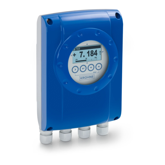
Page 11: Device Description
2 Bar pencil (to operate the signal converter when the housing is closed) 3 Documentation (calibration report, Quick Start, CD-Rom with product documentation for flow sensor and signal con- verter) 4 Signal cable (only for remote version) 09/2016 - 4002184003 - MA IFC 050 R03 en www.krohne.com... -
Page 12: Device Description
OPTIFLUX 2050 C OPTIFLUX 2050 W OPTIFLUX 4000 OPTIFLUX 4050 C OPTIFLUX 4050 W OPTIFLUX 6000 OPTIFLUX 6050 C OPTIFLUX 6050 W WATERFLUX 3000 WATERFLUX 3050 C WATERFLUX 3050 W www.krohne.com 09/2016 - 4002184003 - MA IFC 050 R03 en... -
Page 13: Nameplates
3 Electronic version (ER) 4 Maximum working pressure 5 GK/GKL values (flow sensor constants); size (mm/inch); field frequency; protection category; materials of wetted parts 6 Product designation, serial number and manufacturing date 09/2016 - 4002184003 - MA IFC 050 R03 en www.krohne.com... -
Page 14: Installation
3.5 Mounting of the compact version INFORMATION! The signal converter is mounted directly on the flow sensor. For installation of the flowmeter, please observe the instructions in the supplied product documentation for the flow sensor. www.krohne.com 09/2016 - 4002184003 - MA IFC 050 R03 en... -
Page 15: Mounting Of The Wall Housing, Remote Version
1 Prepare the holes with the aid of the mounting plate. For further information refer to plate, wall version on page 79. 2 Fasten the device securely to the wall with the mounting plate. 09/2016 - 4002184003 - MA IFC 050 R03 en www.krohne.com... - Page 16 Figure 3-2: Dimensions of mounting plate and distances when mounting multiple devices next to each other 1 277 mm / 10.89" 2 310 mm / 12.2" [mm] [inch] Ø6.5 Ø0.26 Ø8.1 Ø0.3 10.5 www.krohne.com 09/2016 - 4002184003 - MA IFC 050 R03 en...
-
Page 17: Electrical Connections
If delivered separately or when installing devices that were not configured together, set the • signal converter to the DN size and GKL of the flow sensor, refer to Function tables on page 09/2016 - 4002184003 - MA IFC 050 R03 en www.krohne.com... -
Page 18: Electrical Cables For Remote Device Versions, Notes
A shielded 2-wire copper cable is used for the field current cable. The shielding MUST MUST be MUST MUST connected in the housing of the flow sensor and signal converter. INFORMATION! The field current cable is not part of the scope of delivery. www.krohne.com 09/2016 - 4002184003 - MA IFC 050 R03 en... -
Page 19: Requirements For Signal Cables Provided By The Customer
• Insulated conductor / insulated conductor 1000 V • Insulated conductor / outer shield 1000 V Twisting of the insulated conductors • At least 10 twists per meter, important for screening magnetic fields. 09/2016 - 4002184003 - MA IFC 050 R03 en www.krohne.com... -
Page 20: Preparing The Signal And Field Current Cables
Cu / AWG 20 3 Insulated wire (3), 0.5 mm Cu / AWG 20 4 Outer sheath 5 Insulation layers 6 Stranded drain wire (6) for the outer shield (60) www.krohne.com 09/2016 - 4002184003 - MA IFC 050 R03 en... -
Page 21: Preparing Signal Cable A, Connection To Signal Converter
4 Crimp the wire end ferrules onto the stranded drain wire. 5 Crimp the wire end ferrules onto the conductors (2, 3). 6 Pull the heat-shrinkable tubing over the prepared signal cable. 09/2016 - 4002184003 - MA IFC 050 R03 en www.krohne.com... -
Page 22: Length Of Signal Cable A
1 Maximum length of signal cable A between the flow sensor and signal converter [m] 2 Maximum length of signal cable A between the flow sensor and signal converter [ft] 3 Electrical conductivity of the medium being measured [μS/cm] www.krohne.com 09/2016 - 4002184003 - MA IFC 050 R03 en... -
Page 23: Preparing Field Current Cable C, Connection To Signal Converter
2 x 0.75 Cu 2 x 18 150...300 492...984 2 x 1.5 Cu 2 x 14 300...600 984...1968 2 x 2.5 Cu 2 x 12 1 Cu = copper cross-section 09/2016 - 4002184003 - MA IFC 050 R03 en www.krohne.com... - Page 24 3 Slide an insulating tube over the stranded drain wire. 4 Crimp a wire end ferrule onto the stranded drain wire. 5 Crimp the wire end ferrules on the conductors. 6 Pull a shrinkable tube over the prepared cable. www.krohne.com 09/2016 - 4002184003 - MA IFC 050 R03 en...
-
Page 25: Preparing Signal Cable A, Connection To Flow Sensor
4 Slide an insulating tube over the stranded drain wire (1). 5 Crimp the wire end ferrules onto conductors 2 and 3 and the stranded drain wire (1). 6 Pull the heat-shrinkable tubing over the prepared signal cable. 09/2016 - 4002184003 - MA IFC 050 R03 en www.krohne.com... -
Page 26: Preparing Field Current Cable C, Connection To Flow Sensor
2 Trim the outer shield to dimension b and pull it over the outer sheath. 3 Crimp wire end ferrules onto both conductors. 4 Pull a shrinkable tube over the prepared cable. www.krohne.com 09/2016 - 4002184003 - MA IFC 050 R03 en... -
Page 27: Connecting The Signal And Field Current Cables
6 Stranded drain wire (1) of the inner shield (10) of the signal cable 7 Electrical conductor (2) 8 Electrical conductor (3) 9 Stranded drain wire (S) of the outer shield (60) 09/2016 - 4002184003 - MA IFC 050 R03 en www.krohne.com... -
Page 28: Connection Diagram For Signal And Field Current Cable
Figure 4-8: Connection diagram for signal and field current cable 1 Electrical terminal compartment in the signal converter 2 Signal cable A 3 Field current cable C 4 Electrical terminal compartment in the flow sensor 5 Functional ground FE www.krohne.com 09/2016 - 4002184003 - MA IFC 050 R03 en... -
Page 29: Grounding The Flow Sensor
III and the output circuits for overvoltage category II. ≤ 16 A) for the infeed power circuit, and also a separator (switch, circuit • Fuse protection (I breaker) to isolate the signal converter must be provided. 09/2016 - 4002184003 - MA IFC 050 R03 en www.krohne.com... - Page 30 • When connecting to functional extra-low voltages, provide a facility for protective separation (PELV) (acc. to VDE 0100 / VDE 0106 and/or IEC 364 / IEC 536 or relevant national regulations). www.krohne.com 09/2016 - 4002184003 - MA IFC 050 R03 en...
-
Page 31: Inputs And Outputs, Overview
R 0 0 Sign. A (D0-) Common Sign. B (D1+) Shielding Description of used abbreviations Current output active or passive Pulse/frequency output active or passive Status output/limit switch active or passive 09/2016 - 4002184003 - MA IFC 050 R03 en www.krohne.com... -
Page 32: Description Of The Inputs And Outputs
• Forward / reverse flow measurement (F/R mode) is possible. INFORMATION! For further information refer to Connection diagrams of outputs on page 36 and refer to Technical data on page 70 www.krohne.com 09/2016 - 4002184003 - MA IFC 050 R03 en... -
Page 33: Pulse Output And Frequency Output
• The pulse and frequency output can also be used as a status output / limit switch. INFORMATION! For further information refer to Connection diagrams of outputs on page 36 and refer to Technical data on page 70 09/2016 - 4002184003 - MA IFC 050 R03 en www.krohne.com... -
Page 34: Status Output And Limit Switch
• For information on the adjustable operating states refer to on page 50. INFORMATION! For further information refer to Connection diagrams of outputs on page 36 and refer to Technical data on page 70 www.krohne.com 09/2016 - 4002184003 - MA IFC 050 R03 en... -
Page 35: Electrical Connection Of The Outputs
• Push the prepared cables through the cable entries and connect the necessary conductors. • Connect the shield. • Close the housing cover. INFORMATION! Ensure that the housing gasket is properly fitted, clean and undamaged. 09/2016 - 4002184003 - MA IFC 050 R03 en www.krohne.com... -
Page 36: Laying Electrical Cables Correctly
• Terminals that are not used should not have any conductive connection to other electrically conductive parts. Description of used abbreviations Current output active or passive Pulse/frequency output active or passive Status output/limit switch active or passive www.krohne.com 09/2016 - 4002184003 - MA IFC 050 R03 en... -
Page 37: Description Of The Electrical Symbols
Electronic or electromagnetic counter At frequencies above 100 Hz, shielded cables must be used to connect the counters. Internal resistance of the counter Button, NO contact or similar Table 4-1: Description of symbols 09/2016 - 4002184003 - MA IFC 050 R03 en www.krohne.com... -
Page 38: Basic And Modbus Outputs
≤ 2 V at I = 22 mA • U • R = (U ) / I L, max ® • HART at connection terminals A Figure 4-14: Current output passive I www.krohne.com 09/2016 - 4002184003 - MA IFC 050 R03 en... - Page 39 = (U ) / I L, min • Can also be set as status output; for the electrical connection refer to status output connection diagram. Figure 4-15: Pulse/frequency output passive P 09/2016 - 4002184003 - MA IFC 050 R03 en www.krohne.com...
- Page 40 ≤ 1 kΩ for f ≤ 10 kHz closed: ≥ 12.5 V at I = 10 mA open: I ≤ 0.05 mA at U = 20 V Figure 4-16: Pulse/frequency output active P www.krohne.com 09/2016 - 4002184003 - MA IFC 050 R03 en...
- Page 41 ≤ 0.2 V at I = 10 mA ≤ 2 V at I = 100 mA open: I ≤ 0.05 mA at U = 32 V Figure 4-17: Status output / limit switch passive S 09/2016 - 4002184003 - MA IFC 050 R03 en www.krohne.com...
-
Page 42: Hart ® Connection
• Multi-drop mode I: I ≤ 32 VDC • U • R ≥ 230 Ω ® Figure 4-19: HART connection passive (I ® 1 HART communicator ® 2 Other devices with HART capability www.krohne.com 09/2016 - 4002184003 - MA IFC 050 R03 en... -
Page 43: Start-Up
↑ and ↓. For information about possible status Status messages and diagnostic information messages, their meaning and cause refer to page 63. 09/2016 - 4002184003 - MA IFC 050 R03 en www.krohne.com... -
Page 44: Operation
7 Magnet keys for operation with closed housing (see table below for function and representation in text) INFORMATION! After 5 minutes of inactivity, there is an automatic return to measuring mode. Previously • changed data is not saved. www.krohne.com 09/2016 - 4002184003 - MA IFC 050 R03 en... - Page 45 Esc (> + ↑) Return to menu mode Return to submenu or without acceptance of function without data acceptance of data Table 6-1: Description of key functionality 09/2016 - 4002184003 - MA IFC 050 R03 en www.krohne.com...
-
Page 46: Display In Measuring Mode With 2 Or 3 Measured Values
(_ _ _ signals in this line the end of the list) 6 Current menu(s), submenu or function 7 Previous menu(s), submenu or function (_ _ _ signals in this line the beginning of the list) www.krohne.com 09/2016 - 4002184003 - MA IFC 050 R03 en... -
Page 47: Display When Setting Parameters, 4 Lines
3 Denotes a changed parameter (simple check of changed data when browsing through lists) 4 Next parameter 5 Currently set data from 6 6 Current parameter (for selection press key >; then see previous chapter) 7 Factory setting of parameter 09/2016 - 4002184003 - MA IFC 050 R03 en www.krohne.com... -
Page 48: Menu Structure
B1 simulation > For details about the > Menu submenus refer to B2 actual values "B test" on page 52. B3 information ↓ ↑ ↓ ↑ ↓ ↑ ↓ ↑ > www.krohne.com 09/2016 - 4002184003 - MA IFC 050 R03 en... - Page 49 C6.4 2. meas. page C6.5 graphic page C6.6 special functions C6.7 units C6.8 quick setup ↓ ↑ ↓ ↑ ↓ ↑ ↓ ↑ > 1 Depending on settings in "C2.2 hardware" 09/2016 - 4002184003 - MA IFC 050 R03 en www.krohne.com...
-
Page 50: Function Tables
A5.2 time constant Time constant for the analogue outputs (current output, frequency output and display). A5.3 low flow cutoff Low flow cutoff for the analogue outputs (current output and frequency output). www.krohne.com 09/2016 - 4002184003 - MA IFC 050 R03 en... - Page 51 A7.6 flow direction Define the polarity of the flow direction. Select: normal direction (according to the arrow on the flow sensor) / reverse direction (in the opposite direction to the arrow) 09/2016 - 4002184003 - MA IFC 050 R03 en www.krohne.com...
-
Page 52: Menu "B Test
Reference identification number, electronic revision and production date of the device; includes all hardware and software changes B3.3 device serial no. Serial number of the system. B3.4 electronic serial no. Serial number of the electronics. www.krohne.com 09/2016 - 4002184003 - MA IFC 050 R03 en... -
Page 53: Menu "C Setup
Only available if "manual" is selected in C1.1.10. Range: 1.0…250 ms C1.1.12 line frequency Setting the line frequency. Select: 50 Hz or 60 Hz C1.1.13 act. coil resistance Display of the actual resistance of the field coil. 09/2016 - 4002184003 - MA IFC 050 R03 en www.krohne.com... - Page 54 Range: xxx.x s; 0.1...100 s A damping is set for empty pipe detection. C1.4 information C1.4.1 liner Shows the material of the liner. C1.4.2 electr. material Shows the material of the electrodes. www.krohne.com 09/2016 - 4002184003 - MA IFC 050 R03 en...
- Page 55 For sequence refer to "B1.2 current output A". C2.2.10 4mA trimming Trimming of the current at 4 mA. Reset to 4 mA restores the factory calibration. ® Used for HART setting. 09/2016 - 4002184003 - MA IFC 050 R03 en www.krohne.com...
- Page 56 Select: off (activated output: switch closed) / on (activated output: switch open) C2.3.8 information Serial number of the I/O board, software version number and production date of the circuit board. C2.3.9 simulation For sequence refer to "B1.3 frequency out D". www.krohne.com 09/2016 - 4002184003 - MA IFC 050 R03 en...
- Page 57 Select: off (activated output: switch closed) / on (activated output: switch open) C2.3.3 information Serial number of the I/O board, software version number and production date of the circuit board. C2.3.4 simulation For sequence refer to "B1.3 status output D". 09/2016 - 4002184003 - MA IFC 050 R03 en www.krohne.com...
- Page 58 Select: no (exits the function without starting the counter) / yes (starts the counter and exits the function) C3._.7 information Serial number of the I/O board, software version number and production date of the circuit board. www.krohne.com 09/2016 - 4002184003 - MA IFC 050 R03 en...
- Page 59 2. meas. page (shows this page) / status page (shows only status messages) / graphic page (trend of the 1st measurement) C6.2.4 magnet keys For activating or deactivating the magnet keys. Select: on (magnet keys are enabled) / off (magnet keys are disabled) 09/2016 - 4002184003 - MA IFC 050 R03 en www.krohne.com...
- Page 60 Display and I/O settings are retained!) Query: go on with copy? (cannot be undone) Select: no (exit function without saving) / yes (load data from the selected storage place) www.krohne.com 09/2016 - 4002184003 - MA IFC 050 R03 en...
- Page 61 Reset counter 2 in menu "quick setup". Select: yes (activated) / no (not activated) C6.8.3 process input Activate quick access to the important process input parameters. Select: yes (activated) / no (not activated) 09/2016 - 4002184003 - MA IFC 050 R03 en www.krohne.com...
-
Page 62: Set Free Units
> Query: reset counter? Select: no ↓ or ↑ Query: reset counter? Select: yes A4.2 counter 1 or A4.3 Counter has been reset. counter 2 3 x ^ Measuring mode www.krohne.com 09/2016 - 4002184003 - MA IFC 050 R03 en... -
Page 63: Deleting Error Messages In The Menu "Quick Setup
Data error in the local data of the measuring Defective, replace electronic unit. sensor electronic equipment. F field current local Data error in the local data of the field Defective, replace electronic unit. current supply. 09/2016 - 4002184003 - MA IFC 050 R03 en www.krohne.com... - Page 64 Error during the CRC check of the active Upload backup 1 or backup 2 settings, check settings. and adjust if necessary. F factory settings Error during the CRC check of the factory settings. www.krohne.com 09/2016 - 4002184003 - MA IFC 050 R03 en...
- Page 65 Message depending on the situation via are possibly simulated values or values with ® HART or FDT. fixed settings. C test sensor Test function of the measuring sensor electronics is active. 09/2016 - 4002184003 - MA IFC 050 R03 en www.krohne.com...
- Page 66 C1.3.2. Check installation. Or set to zero. No measurement possible. electrodes completely insulated e.g. by oil film. Clean! I diagnosis channel off Diagnosis value switched off. Changing of settings in C1.3.17. www.krohne.com 09/2016 - 4002184003 - MA IFC 050 R03 en...
-
Page 67: Service
• such dangerous substances, to enclose a certificate with the device confirming that is safe to handle and stating the • product used. 09/2016 - 4002184003 - MA IFC 050 R03 en www.krohne.com... -
Page 68: Form (For Copying) To Accompany A Returned Device
The user must dispose of the WEEE to a designated collection point for the recycling of WEEE or send them back to our local organisation or authorised representative. www.krohne.com 09/2016 - 4002184003 - MA IFC 050 R03 en... -
Page 69: Technical Data
Q. A signal converter is used to amplify the signal voltage, filter it and convert it into signals for totalizing, recording and output processing. Figure 8-1: Measuring principle 1 Field coils 2 Magnetic field 3 Electrodes 4 Induced voltage (proportional to flow velocity) 09/2016 - 4002184003 - MA IFC 050 R03 en www.krohne.com... -
Page 70: Technical Data
2 internal counters with a max. of 10 counter places (e.g. for counting volume and/or mass units) Verification Integrated verification, diagnostic functions: measuring device, empty pipe detection, stabilisation Communication interfaces ® HART Modbus www.krohne.com 09/2016 - 4002184003 - MA IFC 050 R03 en... - Page 71 Measuring accuracy For detailed information and accuracy curves refer to on page Special calibrations are available on request. Current output electronics: ±10 µA; ±100 ppm/°C (typically: ±30 ppm/°C) Repeatability ±0.1% 09/2016 - 4002184003 - MA IFC 050 R03 en www.krohne.com...
- Page 72 For detailed information refer to chapter "Dimensions and weight". Materials Signal converter housing Aluminum with a polyester topcoat Flow sensor For housing materials, process connections, liners, grounding electrodes and gaskets, refer to technical data for the flow sensor. www.krohne.com 09/2016 - 4002184003 - MA IFC 050 R03 en...
-
Page 73: Electrical Connection
All outputs are electrically isolated from each other and from all other circuits. All operating data and output values can be adjusted. Description of abbreviations = external voltage; R = load + resistance; = terminal voltage; I = nominal current 09/2016 - 4002184003 - MA IFC 050 R03 en www.krohne.com... - Page 74 Load ≥ 250 Ω at HART ® test point; Note maximum load for current output! Multi-drop mode Yes, current output = 4 mA Multi-drop address adjustable in operation menu 1…15 www.krohne.com 09/2016 - 4002184003 - MA IFC 050 R03 en...
- Page 75 = 1.5 V at I ≤ 1 mA 0, max = 2.5 V at I ≤ 10 mA 0, max = 5.0 V at I ≤ 20 mA 0, max 09/2016 - 4002184003 - MA IFC 050 R03 en www.krohne.com...
- Page 76 Other standards and approvals Other standards and approvals Other standards and approvals Shock and vibration resistance IEC 60068-2-3; EN 60068-2-6 and EN 60068-2-27; IEC 61298-3 NAMUR NE 21, NE 43, NE 53 www.krohne.com 09/2016 - 4002184003 - MA IFC 050 R03 en...
-
Page 77: Dimensions And Weight
51.3 1.9 without display Dimensions and weight in inch and lb Dimensions [inch] Weight [lb] Version with & 6.18 1.57 3.15 4.72 9.76 4.39 10.24 1.12 2.02 4.2 without display 09/2016 - 4002184003 - MA IFC 050 R03 en www.krohne.com... - Page 78 Version with & 148.2 95.5 1.8 without display Dimensions and weight in inch and lb Dimensions [inch] Weight [lb] Version with & 6.18 1.57 3.15 5.83 3.98 10.24 3.76 4.0 without display www.krohne.com 09/2016 - 4002184003 - MA IFC 050 R03 en...
-
Page 79: Mounting Plate, Wall Version
TECHNICAL DATA IFC 050 8.3.2 Mounting plate, wall version Dimensions in mm and inch [mm] [inch] Ø6.5 Ø0.26 Ø8.1 Ø0.3 10.5 09/2016 - 4002184003 - MA IFC 050 R03 en www.krohne.com... -
Page 80: Flow Tables
212.06 706.86 2120.58 8482.32 305.37 1017.90 3053.70 12214.80 415.62 1385.40 4156.20 16624.80 542.88 1809.60 5428.80 21715.20 687.06 2290.20 6870.60 27482.40 1000 848.22 2827.40 8482.20 33928.80 1200 1221.45 3421.20 12214.50 48858.00 www.krohne.com 09/2016 - 4002184003 - MA IFC 050 R03 en... - Page 81 7562.58 30250.34 933.86 3112.56 9336.63 37346.53 1344.50 4481.22 13445.04 53780.15 1829.92 6099.12 18299.20 73196.79 2390.23 7966.64 23902.29 95609.15 3025.03 10082.42 30250.34 121001.37 3734.50 12447.09 37346.00 149384.01 5377.88 17924.47 53778.83 215115.30 09/2016 - 4002184003 - MA IFC 050 R03 en www.krohne.com...
-
Page 82: Measuring Accuracy
±0.5% of mv ± 1 mm/s ±0.25% of mv ± 1.5 mm/s OPTIFLUX 2050 10…1200 3/8…48 Extended calibration at OPTIFLUX 4050 2 points OPTIFLUX 6050 10…150 3/8…6 WATERFLUX 3050 25...600 1...24 www.krohne.com 09/2016 - 4002184003 - MA IFC 050 R03 en... -
Page 83: Notes
NOTES IFC 050 09/2016 - 4002184003 - MA IFC 050 R03 en www.krohne.com... - Page 84 • Process Analysis • Services Head Office KROHNE Messtechnik GmbH Ludwig-Krohne-Str. 5 47058 Duisburg (Germany) Tel.: +49 203 301 0 Fax: +49 203 301 10389 info@krohne.com The current list of all KROHNE contacts and addresses can be found at: www.krohne.com...
Need help?
Do you have a question about the IFC 050 and is the answer not in the manual?
Questions and answers