Table of Contents
Advertisement
Quick Links
Advertisement
Table of Contents

Related Manuals for KROHNE MFC 400


Summary of Contents for KROHNE MFC 400
- Page 1 Handbook Handbook Handbook Signal converter for mass flowmeters Electronic Revision: ER 2.0.xx The documentation is only complete when used in combination with the relevant documentation for the flow sensor. © KROHNE 07/2016 - 4002075804 - MA MFC 400 R04 en...
- Page 2 All rights reserved. It is prohibited to reproduce this documentation, or any part thereof, without the prior written authorisation of KROHNE Messtechnik GmbH. Subject to change without notice. Copyright 2016 by KROHNE Messtechnik GmbH - Ludwig-Krohne-Str. 5 - 47058 Duisburg (Germany) www.krohne.com 07/2016 - 4002075804 - MA MFC 400 R04 en...
-
Page 3: Table Of Contents
4.7 Inputs and outputs, overview ..................26 4.7.1 Combinations of the inputs/outputs (I/Os) ................26 4.7.2 Description of the CG number ....................27 4.7.3 Fixed, non-alterable input/output versions................28 4.7.4 Alterable input/output versions.................... 29 07/2016 - 4002075804 - MA MFC 400 R04 en www.krohne.com... - Page 4 6.6.2 Suppress small flow rates ....................92 6.6.3 Polarity of measurement ...................... 93 6.6.4 Current output ........................93 6.6.5 Alarm signalling via current outputs..................94 6.6.6 Pulse output and batching applications ................94 www.krohne.com 07/2016 - 4002075804 - MA MFC 400 R04 en...
- Page 5 9.3.1 Point-to-Point connection - analogue / digital mode............124 9.3.2 Multi-Drop connection (2-wire connection) ............... 125 9.3.3 Multi-Drop connection (3-wire connection) ............... 126 ® 9.4 Inputs/outputs and HART dynamic variables and device variables ............127 10 Notes 07/2016 - 4002075804 - MA MFC 400 R04 en www.krohne.com...
-
Page 6: Safety Instructions
ER 1.0.4x 2-H; 3-P; 3-F MA MFC400 R03 2014-05-06 ER 1.0.5x MA MFC400 R03 2014-08-08 ER 1.0.6x 1; 3-P; 3-I; 2-H MA MFC400 R03 2016-07-01 ER 2.0.0x MA MFC400 R04 www.krohne.com 07/2016 - 4002075804 - MA MFC 400 R04 en... -
Page 7: Intended Use
This device conforms with the most recent and up to date versions of the following: • EMC Directive • ATEX Directive • Low Voltage Directive • Pressure Equipment Directive The manufacturer declares conformity and the device carries the CE mark. 07/2016 - 4002075804 - MA MFC 400 R04 en www.krohne.com... -
Page 8: Safety Instructions From The Manufacturer
The manufacturer reserves the right to alter the content of its documents, including this disclaimer in any way, at any time, for any reason, without prior notification, and will not be liable in any way for possible consequences of such changes. www.krohne.com 07/2016 - 4002075804 - MA MFC 400 R04 en... -
Page 9: Product Liability And Warranty
This document is provided to help you establish operating conditions, which will permit safe and efficient use of this device. Special considerations and precautions are also described in the document, which appear in the form of icons as shown below. 07/2016 - 4002075804 - MA MFC 400 R04 en www.krohne.com... -
Page 10: Warnings And Symbols Used
In general, devices from the manufacturer may only be installed, commissioned, operated and maintained by properly trained and authorized personnel. This document is provided to help you establish operating conditions, which will permit safe and efficient use of this device. www.krohne.com 07/2016 - 4002075804 - MA MFC 400 R04 en... -
Page 11: Device Description
OPTIMASS 2400 C OPTIMASS 2400 F OPTIMASS 3000 OPTIMASS 3400 C OPTIMASS 3400 F OPTIMASS 6000 OPTIMASS 6400 C OPTIMASS 6400 F OPTIMASS 7000 OPTIMASS 7400 C OPTIMASS 7400 F 07/2016 - 4002075804 - MA MFC 400 R04 en www.krohne.com... -
Page 12: Device Description
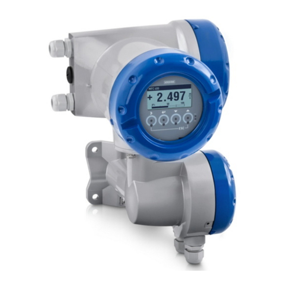
1 Compact version 2 Flow sensor with connection box 3 Field housing Figure 2-3: Versions with straight tube 1 Compact version 2 Flow sensor with connection box 3 Field housing www.krohne.com 07/2016 - 4002075804 - MA MFC 400 R04 en... -
Page 13: Field Housing
Each time a housing cover is opened, the thread should be cleaned and greased. Use only resin- free and acid-free grease. Ensure that the housing gasket is properly fitted, clean and undamaged. 07/2016 - 4002075804 - MA MFC 400 R04 en www.krohne.com... -
Page 14: Nameplates
4 Protection category 5 Electrical connection data 6 Software and hardware revision (Electronics Revision), CG number, order number for signal converter and flow sensor 7 Product description 8 Manufacturer and manufacturer logo www.krohne.com 07/2016 - 4002075804 - MA MFC 400 R04 en... -
Page 15: Electrical Connection Data Of Inputs/Outputs (Example Of Basic Version)
• A = active mode; the signal converter supplies the power for connection of the subsequent devices • P = passive mode; external power supply required for operation of the subsequent devices • N/C = connection terminals not connected 07/2016 - 4002075804 - MA MFC 400 R04 en www.krohne.com... -
Page 16: Installation
Signal converters installed in control cabinets require adequate cooling, e.g. by fan or heat • exchanger. Do not expose the signal converter to intense vibrations. The measuring devices are tested • for a vibration level as described in chapter "Technical data". www.krohne.com 07/2016 - 4002075804 - MA MFC 400 R04 en... -
Page 17: Mounting Of The Compact Version
Figure 3-1: Pipe mounting of the field housing 1 Fix the signal converter to the pipe. 2 Fasten the signal converter using standard U-bolts and washers. 3 Tighten the nuts. 07/2016 - 4002075804 - MA MFC 400 R04 en www.krohne.com... -
Page 18: Wall Mounting
3 Screw the signal converter to the mounting plate with the nuts and washers. Mounting multiple devices next to each other a ≥ 600 mm / 23.6" b ≥ 250 mm / 9.8" www.krohne.com 07/2016 - 4002075804 - MA MFC 400 R04 en... -
Page 19: Turning The Display Of The Field Housing Version
Each time a housing cover is opened, the thread should be cleaned and greased. Use only resin- free and acid-free grease. Ensure that the housing gasket is properly fitted, clean and undamaged. 07/2016 - 4002075804 - MA MFC 400 R04 en www.krohne.com... -
Page 20: Electrical Connections
Use suitable cable entries for the various electrical cables. • The flow sensor and signal converter have been configured together at the factory. For this • reason, please connect the devices in pairs. www.krohne.com 07/2016 - 4002075804 - MA MFC 400 R04 en... -
Page 21: Signal Cable Requirements
• Test voltage: ≥ 100 VAC • Temperature range: -40...+85°C / -40...+185°F • Capacity between cables: ≤ 41 pF/m • Capacity compared to shielding: ≤ 73 pF/m • Inductance: ≤ 0.8 µH/m 07/2016 - 4002075804 - MA MFC 400 R04 en www.krohne.com... -
Page 22: Connecting The Signal Cables
3 Secure the signal cable using the clip. 4 Connect the electrical conductors as shown. The shielding must also be connected to the spring terminal. 5 Re-fit the cover and tighten it by hand. www.krohne.com 07/2016 - 4002075804 - MA MFC 400 R04 en... - Page 23 Each time a housing cover is opened, the thread should be cleaned and greased. Use only resin- free and acid-free grease. Ensure that the housing gasket is properly fitted, clean and undamaged. 07/2016 - 4002075804 - MA MFC 400 R04 en www.krohne.com...
-
Page 24: Connection Diagram
• In hazardous areas, grounding is used at the same time for equipotential bonding. Additional grounding instructions are provided in the supplementary "Ex documentation", which are only supplied together with hazardous area equipment. www.krohne.com 07/2016 - 4002075804 - MA MFC 400 R04 en... -
Page 25: Connecting Power - All Housing Variants
(PELV) (acc. to VDE 0100 / VDE 0106 and/or IEC 364 / IEC 536 or relevant national regulations). INFORMATION! For 24 VDC, 12 VDC - 10% is included in the tolerance range. 07/2016 - 4002075804 - MA MFC 400 R04 en www.krohne.com... -
Page 26: Inputs And Outputs, Overview
• For hazardous areas, all of the input/output variants for the housing designs C and F can be delivered with terminal compartment in Ex d (pressure-resistant casing) or Ex e (increased safety). • For connection and operation of Ex devices, note the supplementary instructions. www.krohne.com 07/2016 - 4002075804 - MA MFC 400 R04 en... -
Page 27: Description Of The Cg Number
Signal converter monitors cable breaks and short circuits acc. to EN 60947-5-6. Errors indicated on LC display. Error messages possible via status output. No additional module installed No further module possible 07/2016 - 4002075804 - MA MFC 400 R04 en www.krohne.com... -
Page 28: Fixed, Non-Alterable Input/Output Versions
E 1 0 active NAMUR V/D+ V/D- V/D+ V/D- passive FISCO Device FISCO Device E 2 0 passive NAMUR V/D+ V/D- V/D+ V/D- passive FISCO Device FISCO Device 1 Changeable www.krohne.com 07/2016 - 4002075804 - MA MFC 400 R04 en... -
Page 29: Alterable Input/Output Versions
H _ _ max. 2 optional modules for term. A + B Common Sign. B Sign. A (D1) (D0) 1 Software configurable 2 Not activated bus terminator 3 Activated bus terminator 07/2016 - 4002075804 - MA MFC 400 R04 en www.krohne.com... -
Page 30: Description Of The Inputs And Outputs
For further information refer to Description of the inputs and outputs on page 36 and refer to Technical data on page 110 DANGER! For devices used in hazardous areas, additional safety notes apply; please refer to the Ex documentation. www.krohne.com 07/2016 - 4002075804 - MA MFC 400 R04 en... -
Page 31: Pulse Output And Frequency Output
For further information refer to Description of the inputs and outputs on page 36 and refer to Technical data on page 110 DANGER! For devices used in hazardous areas, additional safety notes apply; please refer to the Ex documentation. 07/2016 - 4002075804 - MA MFC 400 R04 en www.krohne.com... -
Page 32: Status Output And Limit Switch
For further information refer to Description of the inputs and outputs on page 36 and refer to Technical data on page 110 DANGER! For devices used in hazardous areas, additional safety notes apply; please refer to the Ex documentation. www.krohne.com 07/2016 - 4002075804 - MA MFC 400 R04 en... -
Page 33: Control Input
For further information refer to Description of the inputs and outputs on page 36 and refer to Technical data on page 110 DANGER! For devices used in hazardous areas, additional safety notes apply; please refer to the Ex documentation. 07/2016 - 4002075804 - MA MFC 400 R04 en www.krohne.com... -
Page 34: Electrical Connection Of The Inputs And Outputs
Each time a housing cover is opened, the thread should be cleaned and greased. Use only resin- free and acid-free grease. Ensure that the housing gasket is properly fitted, clean and undamaged. www.krohne.com 07/2016 - 4002075804 - MA MFC 400 R04 en... -
Page 35: Laying Electrical Cables Correctly
2 Tighten the screw connection of the cable entry securely. 3 Never mount the housing with the cable entries facing upwards. 4 Seal cable entries that are not needed with a plug. 07/2016 - 4002075804 - MA MFC 400 R04 en www.krohne.com... -
Page 36: Description Of The Inputs And Outputs
Control input active acc. to NAMUR EN 60947-5-6: Signal converter monitors cable breaks and short circuits acc. to EN 60947-5-6. Errors indicated on LC display. Error messages possible via status output. www.krohne.com 07/2016 - 4002075804 - MA MFC 400 R04 en... -
Page 37: Description Of The Electrical Symbols
Electronic or electromagnetic counter At frequencies above 100 Hz, shielded cables must be used to connect the counters. Internal resistance of the counter Button, NO contact or similar Table 4-1: Description of symbols 07/2016 - 4002075804 - MA MFC 400 R04 en www.krohne.com... -
Page 38: Modular Inputs/Outputs And Bus Systems
≤ (U • R ) / I • X designates the connection terminals A, B or C, depending on the version of the signal converter. Figure 4-7: Current output passive I www.krohne.com 07/2016 - 4002075804 - MA MFC 400 R04 en... - Page 39 L, min L, min • X designates the connection terminals A, B or D, depending on the version of the signal converter. Figure 4-8: Pulse/frequency output active P 07/2016 - 4002075804 - MA MFC 400 R04 en www.krohne.com...
- Page 40 • Can also be set as status output. For the electrical connection refer to status output connection diagram. • X designates the connection terminals A, B or D, depending on the version of the signal converter. Figure 4-9: Pulse/frequency output passive P www.krohne.com 07/2016 - 4002075804 - MA MFC 400 R04 en...
- Page 41 = 3.8 mA • X designates the connection terminals A, B or D, depending on the version of the signal converter. Figure 4-10: Pulse/frequency output passive P acc. to NAMUR EN 60947-5-6 07/2016 - 4002075804 - MA MFC 400 R04 en www.krohne.com...
- Page 42 • The output is open when the device is de-energised. • X designates the connection terminals A, B or D, depending on the version of the signal converter. Figure 4-12: Status output / limit switch passive S www.krohne.com 07/2016 - 4002075804 - MA MFC 400 R04 en...
- Page 43 • X designates the connection terminals A, B or D, depending on the version of the signal converter. Figure 4-13: Status output / limit switch S acc. to NAMUR EN 60947-5-6 07/2016 - 4002075804 - MA MFC 400 R04 en www.krohne.com...
- Page 44 Contact closed (on): U = 1.9 mA • X designates the connection terminals A or B, depending on the version of the signal converter. Figure 4-15: Control input passive C 1 Signal www.krohne.com 07/2016 - 4002075804 - MA MFC 400 R04 en...
- Page 45 ≤ 1.2 V at I ≥ 6.7 mA • X designates the connection terminals A or B, depending on the version of the signal converter. Figure 4-16: Control input active C acc. to NAMUR EN 60947-5-6 07/2016 - 4002075804 - MA MFC 400 R04 en www.krohne.com...
-
Page 46: Ex I Inputs/Outputs
• R ) / I • X designates the connection terminals A or C, depending on the version of the signal converter. Figure 4-18: Current output passive I Ex i www.krohne.com 07/2016 - 4002075804 - MA MFC 400 R04 en... - Page 47 • X designates the connection terminals B or D, depending on the version of the signal converter. Figure 4-19: Pulse/frequency output passive P acc. to NAMUR EN 60947-5-6 Ex i 07/2016 - 4002075804 - MA MFC 400 R04 en www.krohne.com...
- Page 48 • X designates the connection terminals B or D, depending on the version of the signal converter. Figure 4-20: Status output / limit switch S acc. to NAMUR EN 60947-5-6 Ex i www.krohne.com 07/2016 - 4002075804 - MA MFC 400 R04 en...
-
Page 49: Hart ® Connection
Figure 4-22: HART connection active (I 1 Modular I/O: terminals C- and C ® 2 HART communicator communicator must be R ≥ 230 Ω. ® The parallel resistance to the HART 07/2016 - 4002075804 - MA MFC 400 R04 en www.krohne.com... - Page 50 3 Other devices with HART capability CAUTION! For Multi-Drop mode disable the loop current mode (C4.2). ≥ 4 mA • I: I ≤ 32 VDC • U • R ≥ 230 Ω www.krohne.com 07/2016 - 4002075804 - MA MFC 400 R04 en...
-
Page 51: Start-Up
↑ and ↓. For possible status messages, their meaning and cause refer to Diagnostic information and status messages on page 99. 07/2016 - 4002075804 - MA MFC 400 R04 en www.krohne.com... -
Page 52: Operation
Esc (> + ↑) Return to menu mode Return to submenu or without acceptance of function without data acceptance of data www.krohne.com 07/2016 - 4002075804 - MA MFC 400 R04 en... - Page 53 1st measuring page Menu for device configuration 2nd measuring page Menu for device configuration Graphic page Menu for device configuration Status message page Menu for status messages with detailed status information 07/2016 - 4002075804 - MA MFC 400 R04 en www.krohne.com...
-
Page 54: Display In Measuring Mode With 2 Or 3 Measured Values
(_ _ _ signals in this line the end of the list) 6 Current menu(s), submenu or function 7 Previous menu(s), submenu or function (_ _ _ signals in this line the beginning of the list) www.krohne.com 07/2016 - 4002075804 - MA MFC 400 R04 en... -
Page 55: Display When Setting Parameters, 4 Lines
6 Current parameter (for selection press key >; then see previous chapter) 7 Factory setting of parameter Parameter icons Icon Description Changed parameter Factory parameter (not changeable) Lock parameter by write access authentication Lock parameter by jumper or SIL Mode 07/2016 - 4002075804 - MA MFC 400 R04 en www.krohne.com... -
Page 56: Using An Ir Interface (Option)
60 seconds. If this does not happen within the specified time period, the device can be operated using the optical keys again. Upon activation, the LED 3 lights up and the optical keys no longer function. www.krohne.com 07/2016 - 4002075804 - MA MFC 400 R04 en... -
Page 57: Menu Structure
A6.0.0 Unlock Device A6.0.0 Unlock Device A7.0.0 Calibrate Zero A7.0.0 Calibrate Zero A7.0.0 Calibrate Zero A7.0.0 Calibrate Zero A8.0.0 Operation Mode A8.0.0 Operation Mode A8.0.0 Operation Mode A8.0.0 Operation Mode 07/2016 - 4002075804 - MA MFC 400 R04 en www.krohne.com... - Page 58 B3.8.0 IO B (dep. on output type of terminals B) B3.9.0 IO C (dep. on output type of terminals C) B3.10.0 IO D (dep. on output type of terminals D) www.krohne.com 07/2016 - 4002075804 - MA MFC 400 R04 en...
- Page 59 C3.0.0 Totalisers C3.1.0 Totaliser 1 C3.2.0 Totaliser 2 C3.3.0 Totaliser 3 C4.0.0 HART C4.0.0 HART C4.0.0 HART C4.0.0 HART C4.1.0 HART C4.2.0 Loop Current Mode C4.3.0 Identification C4.4.0 HART Dyn. Variables 07/2016 - 4002075804 - MA MFC 400 R04 en www.krohne.com...
- Page 60 C7.2.0 Safety Mode C7.3.0 SIL Verification C7.4.0 Unlock Device C7.5.0 Unlock Password * only available if expert mode is enabled ** only available in device variants certified according to IEC 61508 www.krohne.com 07/2016 - 4002075804 - MA MFC 400 R04 en...
-
Page 61: Function Tables
A3.5.0 Low Flow Cutoff Sets the measurement to "0" for low values. x.xxx ± x.xxx%; range: 0.0…20% (1st value = switching point / 2nd value = hysteresis); condition: 2nd value ≤ 1st value 07/2016 - 4002075804 - MA MFC 400 R04 en www.krohne.com... - Page 62 -10…+10%) / Cancel (return without calibration) A8.0.0 Operation Mode A8.0.0 Operation Mode A8.0.0 Operation Mode A8.0.0 Operation Mode Sets the operating mode. Select: Measuring / Standby / Stop www.krohne.com 07/2016 - 4002075804 - MA MFC 400 R04 en...
-
Page 63: Menu "Test
Simulation of volume flow. Set value (set simulated value in L/h). Query: Start Simulation? Select: Yes (start simulation) / Stop Simulation (stop simulation of volume flow) / Cancel (exit function without simulation) 07/2016 - 4002075804 - MA MFC 400 R04 en www.krohne.com... - Page 64 Fieldbus / Modbus RS 485 / Modbus interface. B5.4.0 V No. Converter Displays the order number of the electronics. B5.5.0 Electronic Revision Displays the electronic revision (ER) of the electronics. www.krohne.com 07/2016 - 4002075804 - MA MFC 400 R04 en...
-
Page 65: Menu "Setup
Available only if density mode "Fixed" has been selected in Fct. C1.2.2. C1.2.4 Ref. Density Temp Sets the reference temperature for the reference density option. Available only if density mode "Referred" has been selected in Fct. C1.2.2. 07/2016 - 4002075804 - MA MFC 400 R04 en www.krohne.com... - Page 66 Temperature coefficient squared for "Product B" (if CCF05 = Other). C1.3.4 CCF08 Defines non-linear equation if CCF01 is set to "Non Linear". C1.3.4 CCF09 Defines non-linear equation if CCF01 is set to "Non Linear". Consult the manufacturer for settings. www.krohne.com 07/2016 - 4002075804 - MA MFC 400 R04 en...
- Page 67 Select: Disabled (goes to zero) / Sensor Average (sensor amplitude A+B) / Sensor C1.5.3 Diagnosis 2 Deviation / Drive Level / Tube Frequency / Strain 1 / Strain 2 / 2 Phase Signal 07/2016 - 4002075804 - MA MFC 400 R04 en www.krohne.com...
- Page 68 Min. and max. limits of current values. If the current range is exceeded, the current is set to these limits. xx.x…xx.x mA; range: 03.5…21.5 mA (Condition: 0 mA ≤ 1st value ≤ 2nd value ≤ 21.5 mA and out of current range) www.krohne.com 07/2016 - 4002075804 - MA MFC 400 R04 en...
- Page 69 Sets the measurement to "0" for low values. x.xxx ± x.xxx%; range: 0.0…20% (1st value = switching point / 2nd value = hysteresis); condition: 2nd value ≤ 1st value C2._.4 Damping Range: 0.0…100 s 07/2016 - 4002075804 - MA MFC 400 R04 en www.krohne.com...
- Page 70 (display for negative values = 0) / Negative Polarity (display for positive values = 0) / Absolute Value (displayed value is positive for both negative and positive measurement values) Note: Only available if expert mode in C6.4.5 is enabled! www.krohne.com 07/2016 - 4002075804 - MA MFC 400 R04 en...
- Page 71 Select: Off (activated output: switch closed) / On (activated output: switch open) C2._.4 Information* Serial no. of the I/O board, software version no. and production date of the circuit board. Note: Only available if expert mode in C6.4.5 is enabled! 07/2016 - 4002075804 - MA MFC 400 R04 en www.krohne.com...
- Page 72 Select: Off (activated output: switch closed) / On (activated output: switch open) C2._.3 Information Serial number of the I/O board, software version number and production date of the circuit board. www.krohne.com 07/2016 - 4002075804 - MA MFC 400 R04 en...
- Page 73 Select: No (exits the function without starting the totaliser) / Yes (starts the totaliser and exits the function) C3._.10 Information Serial number of the I/O board, software version number and production date of the circuit board. 07/2016 - 4002075804 - MA MFC 400 R04 en www.krohne.com...
- Page 74 Average / Sensor Deviation / Drive Level / Tube Frequency / Strain 1 / Strain 2 / 2 Phase Signal / Totaliser 1 Mass / Totaliser 1 Volume / Totaliser 2 Mass / Totaliser 2 Volume www.krohne.com 07/2016 - 4002075804 - MA MFC 400 R04 en...
- Page 75 C5._.5 Low Flow Cutoff Sets the measurement to "0" for low values. x.xxx ± x.xxx%; Range: 0.0…20% (1st value = switching point / 2nd value = hysteresis), condition: 2nd value ≤ 1st value 07/2016 - 4002075804 - MA MFC 400 R04 en www.krohne.com...
- Page 76 C6.1.0 Tag ® Measuring point identifier (Tag no.) (also for HART operation) will be displayed in the LCD header (max. 8 digits). C6.2.0 Reset Errors Reset Errors? Select: No / Yes www.krohne.com 07/2016 - 4002075804 - MA MFC 400 R04 en...
- Page 77 For text to be specified refer to Set free units on page 79: C6.5.6 [kg/s]*Factor Specification of the conversion factor, based on kg/s: Set free units xxx.xxx refer to on page 79 07/2016 - 4002075804 - MA MFC 400 R04 en www.krohne.com...
- Page 78 Required and Function Check) for the group "Electr: Power Failure". C6.6.7 Electr: IO connection Selection of status signal (Out of Specification, Failure, Information, Maintenance Required and Function Check) for the group "Electr: IO connection". www.krohne.com 07/2016 - 4002075804 - MA MFC 400 R04 en...
-
Page 79: Set Free Units
Conversion factors Conversion factors Desired unit = [unit see above] * conversion factor Conversion factor Max. 9 digits ↑ to the left and ↓ to the right Shift decimal point 07/2016 - 4002075804 - MA MFC 400 R04 en www.krohne.com... -
Page 80: Calibration Functions
Please Wait A progress bar indicates the progress of zero calibration. Calibrate Zero Passed Calibrate Zero Display of measured zero calibration in %. +XX.XXX% 5 x ^ Save Configuration? Display page www.krohne.com 07/2016 - 4002075804 - MA MFC 400 R04 en... - Page 81 Only fill the flow sensor with the carrier medium. may fall out. Two-phase media in which the solids or gas- Fill flow sensor with another liquid, e.g. water. forming components cannot be separated. 07/2016 - 4002075804 - MA MFC 400 R04 en www.krohne.com...
-
Page 82: Density Calibration (C1.2.1 Calibrate Density)
Press ↓ Density Calib. Product until Town Water Calibrate Density? Please Wait A progress bar indicates the progress of zero calibration. Calibrate Density Passed 5 x ^ Save Configuration? Display page www.krohne.com 07/2016 - 4002075804 - MA MFC 400 R04 en... - Page 83 1 point calibration. In other words, there can be weeks or even months between the calibration of the two measuring points. 07/2016 - 4002075804 - MA MFC 400 R04 en www.krohne.com...
-
Page 84: Temperature/Density Tables
83.3 996.0939 62.18614 84.2 995.9487 62.17708 29.5 85.1 995.8013 62.16788 995.6518 62.15855 30.5 86.9 995.5001 62.14907 87.8 995.3462 62.13947 31.5 88.7 995.1903 62.12973 89.6 995.0322 62.11986 32.5 90.5 994.8721 62.10987 www.krohne.com 07/2016 - 4002075804 - MA MFC 400 R04 en... - Page 85 142.7 982.5419 61.34009 143.6 982.2841 61.324 62.5 144.5 982.0250 61.30783 145.4 981.7646 61.29157 63.5 146.3 981.5029 61.27523 147.2 981.2399 61.25881 64.5 148.1 980.9756 61.24231 980.7099 61.22573 65.5 149.9 980.4432 61.20907 07/2016 - 4002075804 - MA MFC 400 R04 en www.krohne.com...
- Page 86 168.8 974.5606 60.84182 76.5 169.7 974.2679 60.82355 170.6 973.9741 60.80520 77.5 171.5 973.6792 60.7868 172.4 973.3832 60.76832 78.5 173.3 973.0862 60.74977 174.2 972.7881 60.73116 79.5 175.1 972.489 60.71249 972.188 60.69375 www.krohne.com 07/2016 - 4002075804 - MA MFC 400 R04 en...
-
Page 87: Measurement Functions
The low flow cutoff is enabled by default sets all flow measurement variables to zero when the flow is below the low flow cutoff value entered. This parameter is only available if the device is switched to expert mode (C6.4.5). 07/2016 - 4002075804 - MA MFC 400 R04 en www.krohne.com... - Page 88 The signal converter can provide the flow velocity based on a pipe diameter which the operator can freely program (C1.1.9). This value can either be the inner diameter of the measuring tube (factory setting) or the inner diameter of the process pipe. www.krohne.com 07/2016 - 4002075804 - MA MFC 400 R04 en...
-
Page 89: Density (C1.2.0 Density)
The following equation is used to calculate the density gradient: The following equation is used to calculate the density gradient: The following equation is used to calculate the density gradient: - ρ a = (ρ ) / (T 07/2016 - 4002075804 - MA MFC 400 R04 en www.krohne.com... -
Page 90: System Control (C1.4.0 System Control)
Selecting the process measurement which activates the system control. Density and temperature can be selected. C1.4.3 Max. Temperature/Density & C1.4.3 Min. Temperature/Density Setting the limit values to activate system control. Current measuring values outside of this range activate this function. www.krohne.com 07/2016 - 4002075804 - MA MFC 400 R04 en... -
Page 91: Detection Of 2 Phase Flow
In case of two phase flow the status message "2 Phase Flow Detected" is generated. C6.6.3 Proc: 2 Phase Flow Select the status signal for two phase flow. 07/2016 - 4002075804 - MA MFC 400 R04 en www.krohne.com... -
Page 92: I/O Configuration
Condition: 1st value > 2nd value 1 Flow 2 Time 3 Currently indicated flow 4 Display set to zero 5 Currently indicated flow 6 Positive hysteresis 7 Operating point 8 Negative hysteresis www.krohne.com 07/2016 - 4002075804 - MA MFC 400 R04 en... -
Page 93: Polarity Of Measurement
Custom values Custom values 1 Only available if HART is disabled or not available for respective current output 2 Low alarm signalling is not recommended for current span 0...20 mA 07/2016 - 4002075804 - MA MFC 400 R04 en www.krohne.com... -
Page 94: Alarm Signalling Via Current Outputs
This function can deactivate the optical keys. In this case, the device may only be operated using the push buttons. In the display, the switched off state of the optical keys is represented the following symbol in the upper right corner: www.krohne.com 07/2016 - 4002075804 - MA MFC 400 R04 en... -
Page 95: Backlight (C5.4.0 Backlight)
Any configuration change of the signal converter is logged within a change log (B1.2.0) with date and time and a checksum of the signal converter configuration. The change log covers all device parameters (incl. factory parameters) and provides 128 entries. 07/2016 - 4002075804 - MA MFC 400 R04 en www.krohne.com... -
Page 96: Locking Of Configuration
(0000). Service Service password. Jumper Application Remove jumper. Specific Lock A lock of parameters and functions via access authentication is indicated as depicted in the following figure: www.krohne.com 07/2016 - 4002075804 - MA MFC 400 R04 en... - Page 97 The lock is enabled directly after applying the jumper and is indicated by a lock icon in the upper right corner or at the locked parameter or function. Changes to these parameters only can be performed after removal of the lock jumper. 07/2016 - 4002075804 - MA MFC 400 R04 en www.krohne.com...
-
Page 98: Special Functions
Once started simulation functions continue until they are stopped or the device performs a power cycle. The device status "Function Check" indicates running simulation functions. Use function "A2.2.0 Stop all Simulations" to stop all running simulation functions simultaneously. www.krohne.com 07/2016 - 4002075804 - MA MFC 400 R04 en... -
Page 99: Diagnostic Information And Status Messages
As status message always the name of the relevant status group and the status signal is displayed. The variable status signal can be changed in menu C6.6. Changing the status signal to "Information" switches off the message. 07/2016 - 4002075804 - MA MFC 400 R04 en www.krohne.com... -
Page 100: Status Groups (C6.6.0 Status Groups)
The history of status messages is logged by the signal converter with date and time. Menu B1.1.0 shows the log of a status event. Shows the beginning of a status event. Shows the end of a status event. www.krohne.com 07/2016 - 4002075804 - MA MFC 400 R04 en... -
Page 101: Reset Errors (A2.1.0 Reset Errors)
MFC 400 6.12.3 Reset errors (A2.1.0 Reset Errors) Some diagnostic functions generate latching status messages which need to be acknowledged by the operator. For this purpose use "Reset Errors" in A2.1.0. 07/2016 - 4002075804 - MA MFC 400 R04 en www.krohne.com... -
Page 102: Service
• Carefully push the electronics back into the housing. • Tighten the 2 locking screws again and secure the display. The measuring system recognises the hardware replacement when the power supply is switched on. www.krohne.com 07/2016 - 4002075804 - MA MFC 400 R04 en... -
Page 103: Driver Or Sensor Coil Fault
Failure of two or more of the upper circuits may indicate a measuring tube error. There may be product in the housing. If this is the case, depressurise depressurise depressurise depressurise the process line and immediately remove the measuring device from the process line. 07/2016 - 4002075804 - MA MFC 400 R04 en www.krohne.com... -
Page 104: Optimass 2000
Failure of two or more of the upper circuits may indicate a measuring tube error. There may be product in the housing. If this is the case, depressurise depressurise depressurise depressurise the process line and immediately remove the measuring device from the process line. www.krohne.com 07/2016 - 4002075804 - MA MFC 400 R04 en... -
Page 105: Optimass 3000
Failure of two or more of the upper circuits may indicate a measuring tube error. There may be product in the housing. If this is the case, depressurise depressurise depressurise depressurise the process line and immediately remove the measuring device from the process line. 07/2016 - 4002075804 - MA MFC 400 R04 en www.krohne.com... -
Page 106: Optimass 6000
Failure of two or more of the upper circuits may indicate a measuring tube error. There may be product in the housing. If this is the case, depressurise depressurise depressurise depressurise the process line and immediately remove the measuring device from the process line. www.krohne.com 07/2016 - 4002075804 - MA MFC 400 R04 en... -
Page 107: Optimass 7000
Failure of two or more of the upper circuits may indicate a measuring tube error. There may be product in the housing. If this is the case, depressurise depressurise the process line and immediately remove depressurise depressurise the measuring device from the process line. 07/2016 - 4002075804 - MA MFC 400 R04 en www.krohne.com... -
Page 108: Spare Parts Availability
• such dangerous substances, to enclose a certificate with the device confirming that is safe to handle and stating the • product used. www.krohne.com 07/2016 - 4002075804 - MA MFC 400 R04 en... -
Page 109: Form (For Copying) To Accompany A Returned Device
The user must dispose of the WEEE to a designated collection point for the recycling of WEEE or send them back to our local organisation or authorised representative. 07/2016 - 4002075804 - MA MFC 400 R04 en www.krohne.com... -
Page 110: Technical Data
Integrated verification, diagnostic functions: measuring device, process, measured value, stabilisation Concentration measurement Universal concentration measurement, °Brix, °Baume, °Plato, alcohol concentration, NaOH and API density Communication interfaces ® Foundation Fieldbus, Profibus PA and DP, Modbus, HART www.krohne.com 07/2016 - 4002075804 - MA MFC 400 R04 en... - Page 111 Signal converter and inputs/outputs: Data bus monitoring, current output Signal converter and inputs/outputs: Signal converter and inputs/outputs: connections, current readback with redundant calibration, factory calibration integrity, electronics temperature, CPU diagnostics, voltage monitoring 07/2016 - 4002075804 - MA MFC 400 R04 en www.krohne.com...
- Page 112 IP66/67 (acc. to NEMA 4/4X) IEC 529 / EN 60529 Installation conditions Installation For detailed information, refer to chapter "Installation conditions". Dimensions and weights For detailed information refer to chapter "Dimensions and weights". www.krohne.com 07/2016 - 4002075804 - MA MFC 400 R04 en...
-
Page 113: Electrical Connection
10 core shielded cable. Detailed specifications are available on request. Length: max. 20 m / 65.6 ft Cable entries Standard: M20 x 1.5 (8...12 mm) Option: 1/2 NPT, PF 1/2 07/2016 - 4002075804 - MA MFC 400 R04 en www.krohne.com... -
Page 114: Inputs And Outputs
≥ 1.8 V ≥ 4 V ≤ (U ≤ (U ) / I ) / I = 30 V = 100 mA = 1 W = 10 nF ~ 0 mH www.krohne.com 07/2016 - 4002075804 - MA MFC 400 R04 en... - Page 115 = 22.5 V at I = 1 mA 0, nom = 21.5 V at I = 10 mA 0, nom = 19 V at I = 20 mA 0, nom 07/2016 - 4002075804 - MA MFC 400 R04 en www.krohne.com...
- Page 116 The time constant corresponds to the elapsed time until 63% of the end value has been reached according to a step function. Settings Set in increments of 0.1 seconds. 0…100 seconds www.krohne.com 07/2016 - 4002075804 - MA MFC 400 R04 en...
- Page 117 R = 1 kΩ ± 10 Ω open: closed: = 0.6 mA = 4.5 mA closed: = 30 V = 100 mA = 3.8 mA = 1 W = 10 nF = 0 mH 07/2016 - 4002075804 - MA MFC 400 R04 en www.krohne.com...
- Page 118 < 1.9 mA 0, nom Detection of cable break: ≥ 8.1 V with I ≤ 0.1 mA Detection of cable short circuit: ≤ 1.2 V with I ≥ 6.7 mA www.krohne.com 07/2016 - 4002075804 - MA MFC 400 R04 en...
- Page 119 Modbus RTU, Master/Slave, RS485 Address range 1…247 Supported function codes 01, 03, 04, 05, 08, 16, 43 Supported Baud rate 1200, 2400, 3600, 4800, 9600, 19200, 38400, 57600, 115200 Baud 07/2016 - 4002075804 - MA MFC 400 R04 en www.krohne.com...
- Page 120 Vibration resistance IEC EN 60068-2-6 10 cycles 10-150-10 Hz with: 0.15 mm for 10-60 Hz and 20 m/s² for 60-150 Hz NAMUR NE 21, NE 43, NE 53, NE 107 www.krohne.com 07/2016 - 4002075804 - MA MFC 400 R04 en...
-
Page 121: Dimensions And Weight
202 / 7.75 120 / 4.75 155 / 6.10 295.8 / 11.60 277 / 10.90 5.7 / 12.60 8.3.2 Mounting plate, field housing Dimensions in mm and inch [mm] [inch] Ø9 Ø0.4 07/2016 - 4002075804 - MA MFC 400 R04 en www.krohne.com... -
Page 122: Description Of Hart Interface
Extended Device Type: 0x45BB Device Revision: DD Revision: ® HART Universal Revision: ≥ 3.3 FC 375/475 system SW.Rev.: ≥ 8.0 AMS version: ≥ 6.0 PDM version: ≥ 1.2 FDT version: www.krohne.com 07/2016 - 4002075804 - MA MFC 400 R04 en... -
Page 123: Connection Variants
"Electrical connection". ® There are two ways of using the HART communication: • as Point-to-Point connection and • as multi-drop connection, with 2-wire connection or as multi-drop connection, with 3-wire connection. 07/2016 - 4002075804 - MA MFC 400 R04 en www.krohne.com... -
Page 124: Point-To-Point Connection - Analogue / Digital Mode
7 Signal converter with address = 0 and passive or active current output 8 Secondary Master 9 Power supply for devices (slaves) with passive current output 10 Load ≥ 250 Ω (Ohm) www.krohne.com 07/2016 - 4002075804 - MA MFC 400 R04 en... -
Page 125: Multi-Drop Connection (2-Wire Connection)
7 Signal converter with address > 0 and passive current output, connection of max. 15 devices (slaves) with 4…20 mA 8 Secondary Master 9 Power supply 10 Load ≥ 250 Ω (Ohm) 07/2016 - 4002075804 - MA MFC 400 R04 en www.krohne.com... -
Page 126: Multi-Drop Connection (3-Wire Connection)
6 Signal converter terminals C- 7 Connection of active or passive 4-wire devices (slaves) with 4…20 mA, addresses > 0 8 Load ≥ 250 Ω (Ohm) 9 Secondary Master 10 Power supply www.krohne.com 07/2016 - 4002075804 - MA MFC 400 R04 en... -
Page 127: Inputs/Outputs And Hart ® Dynamic Variables And Device Variables
2) is set to "2 Phase Signal". Concentration 1 linear Available when concentration measurement is switched on. Concentration 2 linear Available when concentration measurement is switched on and Concentration 2 is not switched off. 07/2016 - 4002075804 - MA MFC 400 R04 en www.krohne.com... - Page 128 Both linear and totaliser device variables can be assigned. The totaliser device variables can only be assigned to the dynamic variables SV, TV and 4V if the connected output is not a current or frequency output. www.krohne.com 07/2016 - 4002075804 - MA MFC 400 R04 en...
-
Page 129: Notes
NOTES MFC 400 07/2016 - 4002075804 - MA MFC 400 R04 en www.krohne.com... - Page 130 NOTES MFC 400 www.krohne.com 07/2016 - 4002075804 - MA MFC 400 R04 en...
- Page 131 NOTES MFC 400 07/2016 - 4002075804 - MA MFC 400 R04 en www.krohne.com...
- Page 132 • Process Analysis • Services Head Office KROHNE Messtechnik GmbH Ludwig-Krohne-Str. 5 47058 Duisburg (Germany) Tel.: +49 203 301 0 Fax: +49 203 301 10389 info@krohne.com The current list of all KROHNE contacts and addresses can be found at: www.krohne.com...
Need help?
Do you have a question about the MFC 400 and is the answer not in the manual?
Questions and answers