Table of Contents
Advertisement
IFC 100
IFC 100
IFC 100
IFC 100
Quick Start
Quick Start
Quick Start
Quick Start
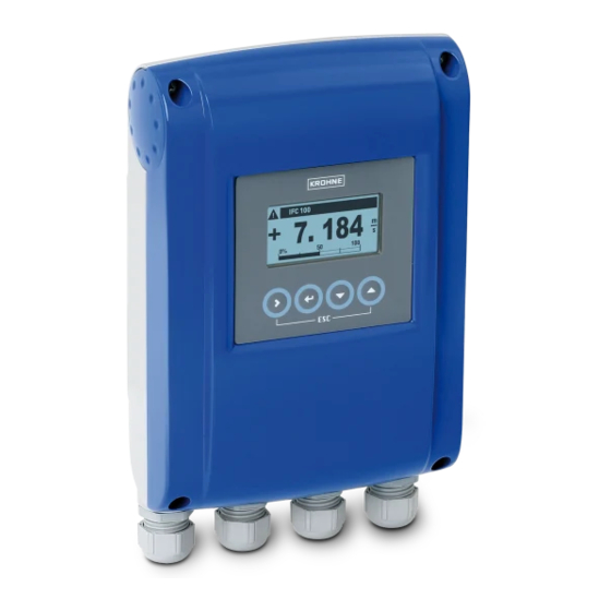
Signal converter for electromagnetic flowmeters
Electronic Revision:
ER 2.1.xx
(SW.REV. 3.0x)
The documentation is only complete when used in combination with the relevant
documentation for the sensor.
© KROHNE 07/2010 - 4000124104 - QS IFC 100 R04 en
Advertisement
Table of Contents

Related Manuals for KROHNE IFC 100


Summary of Contents for KROHNE IFC 100
- Page 1 Quick Start Signal converter for electromagnetic flowmeters Electronic Revision: ER 2.1.xx (SW.REV. 3.0x) The documentation is only complete when used in combination with the relevant documentation for the sensor. © KROHNE 07/2010 - 4000124104 - QS IFC 100 R04 en...
-
Page 2: Table Of Contents
3.9.1 Electrical connection of the outputs..................27 3.9.2 Laying electrical cables correctly..................28 4 Start-up 4.1 Switching on the power ....................29 4.2 Starting the signal converter ..................29 5 Notes www.krohne.com 07/2010 - 4000124104 - QS IFC 100 R04 en... -
Page 3: Safety Instructions
If you need to return the device to the manufacturer or supplier, please fill out the form • contained on the CD-ROM and send it with the device. Unfortunately, the manufacturer cannot repair or inspect the device without the completed form. 07/2010 - 4000124104 - QS IFC 100 R04 en www.krohne.com... -
Page 4: Installation
1 Device in the version as ordered 2 Documentation (calibration report, Quick Start, CD-ROM with product documentation for measuring sensor and signal converter) 3 Signal cable (only for remote version) www.krohne.com 07/2010 - 4000124104 - QS IFC 100 R04 en... -
Page 5: Storage
Signal converters installed in control cabinets require adequate cooling, e.g. by fan or heat • exchanger. • Do not expose the signal converter to intense vibration. The flowmeters are tested for a vibration level in accordance with IEC 68-2-3. 07/2010 - 4000124104 - QS IFC 100 R04 en www.krohne.com... -
Page 6: Mounting Of The Compact Version
1 Prepare the holes with the aid of the mounting plate. For further information refer to Mounting plate, wall-mounted version on page 8. 2 Fasten the device securely to the wall with the mounting plate. www.krohne.com 07/2010 - 4000124104 - QS IFC 100 R04 en... - Page 7 INSTALLATION IFC 100 Mounting multiple devices next to each other [mm] [inches] Ø6.5 Ø0.26 87.2 12.2 10.1 07/2010 - 4000124104 - QS IFC 100 R04 en www.krohne.com...
-
Page 8: Mounting Plate, Wall-Mounted Version
INSTALLATION IFC 100 2.7.2 Mounting plate, wall-mounted version Dimensions in mm and inches [mm] [inches] Ø6.5 Ø0.26 87.2 www.krohne.com 07/2010 - 4000124104 - QS IFC 100 R04 en... -
Page 9: Electrical Connections
Ensure that the sensor constant GK/GKL (see type plates) are identically set. • If delivered separately or when installing devices that were not configured together, set the converter to the DN size and GK/GKL of the sensor. 07/2010 - 4000124104 - QS IFC 100 R04 en www.krohne.com... -
Page 10: Electrical Cables For Remote Device Versions, Notes
A shielded two-wire copper cable is used as the field current cable. The shielding MUST MUST be MUST MUST connected in the housing of the measuring sensor and signal converter. INFORMATION! The field current cable is not part of the scope of supply. www.krohne.com 07/2010 - 4000124104 - QS IFC 100 R04 en... -
Page 11: Requirements For Signal Cables Provided By The Customer
• Insulated conductor / insulated conductor 1000 V • Insulated conductor / outer shield 1000 V Twisting of the insulated conductors • At least 10 twists per meter, important for screening magnetic fields. 07/2010 - 4000124104 - QS IFC 100 R04 en www.krohne.com... -
Page 12: Preparing The Signal And Field Current Cables
Cu / AWG 20 3 Insulated wire (3), 0.5 mm Cu / AWG 20 4 Outer sheath 5 Insulation layers 6 Stranded drain wire (6) for the outer shield (60) www.krohne.com 07/2010 - 4000124104 - QS IFC 100 R04 en... -
Page 13: Length Of Signal Cable A
1 Maximum length of signal cable A between the measuring sensor and signal converter [m] 2 Maximum length of signal cable A between the measuring sensor and signal converter [ft] 3 Electrical conductivity of the medium being measured [μS/cm] 07/2010 - 4000124104 - QS IFC 100 R04 en www.krohne.com... -
Page 14: Preparing Signal Cable A, Connection To Signal Converter
4 Crimp the wire end ferrules onto the stranded drain wire. 5 Crimp the wire end ferrules onto the conductors (2, 3). 6 Pull the heat-shrinkable tubing over the prepared signal cable. www.krohne.com 07/2010 - 4000124104 - QS IFC 100 R04 en... -
Page 15: Preparing Field Current Cable C, Connection To Signal Converter
2 x 0.75 Cu 2 x 18 150...300 500...1000 2 x 1.50 Cu 2 x 14 300...600 1000...2000 2 x 2.50 Cu 2 x 12 1 Cu = copper cross-section 07/2010 - 4000124104 - QS IFC 100 R04 en www.krohne.com... - Page 16 3 Slide an insulating tube over the stranded drain wire. 4 Crimp a wire end ferrule onto the stranded drain wire. 5 Crimp wire end ferrules onto the conductors. 6 Pull a shrinkable tube over the prepared cable. www.krohne.com 07/2010 - 4000124104 - QS IFC 100 R04 en...
-
Page 17: Prepare Signal Cable A, Connect To Measuring Sensor
4 Slide an insulating tube over the stranded drain wire (1). 5 Crimp the wire end ferrules onto conductors 2 and 3 and the stranded drain wire (1). 6 Pull the heat-shrinkable tubing over the prepared signal cable. 07/2010 - 4000124104 - QS IFC 100 R04 en www.krohne.com... -
Page 18: Preparing Field Current Cable C, Connection To Measuring Sensor
2 Trim the outer shield to dimension b and pull it over the outer sheath. 3 Crimp wire end ferrules onto both conductors. 4 Pull a shrinkable tube over the prepared cable. www.krohne.com 07/2010 - 4000124104 - QS IFC 100 R04 en... -
Page 19: Connecting The Signal And Field Current Cables
Observe without fail the local occupational health and safety regulations. Any work done on the electrical components of the measuring device may only be carried out by properly trained specialists. 07/2010 - 4000124104 - QS IFC 100 R04 en www.krohne.com... -
Page 20: Connecting The Signal And Field Current Cables To The Signal Converter, Remote Version
2 Lift the housing at the top and bottom at the same time. 3 Slide the housing cover upward. 4 The housing cover is guided and held by the inside hinge. www.krohne.com 07/2010 - 4000124104 - QS IFC 100 R04 en... - Page 21 6 Stranded drain wire (1) of the inner shield (10) of the signal cable 7 Electrical conductor (2) 8 Electrical conductor (3) 9 Stranded drain wire (S) of the outer shield (60) 07/2010 - 4000124104 - QS IFC 100 R04 en www.krohne.com...
-
Page 22: Connection Diagram For Signal And Field Current Cable
Figure 3-10: Connection diagram for signal and field current cable 1 Electrical terminal compartment in signal converter 2 Signal cable A 3 Field current cable C 4 Electrical terminal compartment in measuring sensor 5 Functional ground FE www.krohne.com 07/2010 - 4000124104 - QS IFC 100 R04 en... -
Page 23: Grounding The Measuring Sensor
• The documentation for the measuring sensors also contain descriptions on how to use grounding rings and how to install the measuring sensors in metal or plastic pipes or in pipes which are coated on the inside. 07/2010 - 4000124104 - QS IFC 100 R04 en www.krohne.com... -
Page 24: Connecting The Power
1 Retaining band of the cover 2 Cable entry power supply remote version 3 Cable entry power supply compact version Version overview Version Non-Ex 100...230 VAC Standard Optional 12...24 VDC Standard 24 VAC/DC Standard www.krohne.com 07/2010 - 4000124104 - QS IFC 100 R04 en... - Page 25 (PELV) (acc. to VDE 0100 / VDE 0106 and IEC 364 / IEC 536 or relevant national regulations). INFORMATION! 12 V is not not included in the tolerance range. 07/2010 - 4000124104 - QS IFC 100 R04 en www.krohne.com...
-
Page 26: Overview Of Outputs
® + HART active 1 function changed by reconnecting 2 changeable Description of used abbreviations Current output active or passive Pulse/frequency output passive Status output / limit switch passive www.krohne.com 07/2010 - 4000124104 - QS IFC 100 R04 en... -
Page 27: Electrical Connection Of The Outputs
• Push the prepared cables through the cable entries and connect the necessary conductors. • Connect the shield. • Close the housing cover. INFORMATION! Ensure that the housing gasket is properly fitted, clean and undamaged. 07/2010 - 4000124104 - QS IFC 100 R04 en www.krohne.com... -
Page 28: Laying Electrical Cables Correctly
2 Tighten the screw connection of the cable entry securely. 3 Seal cable entries that are not needed with a plug. www.krohne.com 07/2010 - 4000124104 - QS IFC 100 R04 en... -
Page 29: Start-Up
It is possible to change between the two measured value windows, the trend display and the list with the status messages by pressing the keys ↑ and ↓. 07/2010 - 4000124104 - QS IFC 100 R04 en www.krohne.com... -
Page 30: Notes
NOTES IFC 100 www.krohne.com 07/2010 - 4000124104 - QS IFC 100 R04 en... - Page 31 NOTES IFC 100 07/2010 - 4000124104 - QS IFC 100 R04 en www.krohne.com...
- Page 32 Measuring systems for the oil and gas industry • Measuring systems for sea-going tankers Head Office KROHNE Messtechnik GmbH Ludwig-Krohne-Str. 5 D-47058 Duisburg (Germany) Tel.:+49 (0)203 301 0 Fax:+49 (0)203 301 10389 info@krohne.de The current list of all KROHNE contacts and addresses can be found at: www.krohne.com...
Need help?
Do you have a question about the IFC 100 and is the answer not in the manual?
Questions and answers