
Related Manuals for KROHNE AF-E 400


Summary of Contents for KROHNE AF-E 400
- Page 1 AF-E 400 Handbook Electromagnetic flowmeter 80290423 © KROHNE 09/2020 - 4007953602 - MA AF-E 400 R02 en...
-
Page 2: Table Of Contents
Contents 1 Preliminary note ���������������������������������������������������������������������������������������������������4 1�1 Symbols used ������������������������������������������������������������������������������������������������5 1�2 Warnings used �����������������������������������������������������������������������������������������������5 2 Safety instructions �����������������������������������������������������������������������������������������������5 3 Getting started �����������������������������������������������������������������������������������������������������6 3�1 Device functions with factory setting �������������������������������������������������������������6 3�2 Setting options �����������������������������������������������������������������������������������������������7 4 Functions and features ����������������������������������������������������������������������������������������7 4�1 Pressure Equipment Directive (PED) �����������������������������������������������������������7 4�2 Applications ���������������������������������������������������������������������������������������������������7 5 Function ���������������������������������������������������������������������������������������������������������������8 5�1 Process measured signals ����������������������������������������������������������������������������8... - Page 3 6�3 Ground ��������������������������������������������������������������������������������������������������������28 6�4 Installation in pipes �������������������������������������������������������������������������������������29 7 Electrical connection �����������������������������������������������������������������������������������������30 8 Operating and display elements �����������������������������������������������������������������������32 9 Menu �����������������������������������������������������������������������������������������������������������������33 9�1 Process value display (RUN) ����������������������������������������������������������������������33 9�2 Main menu ��������������������������������������������������������������������������������������������������34 9�3 Extended functions EF �������������������������������������������������������������������������������35 9�4 Submenu OUT1 and OUT2 ������������������������������������������������������������������������36 9�5 Submenu CFG and TOTL ���������������������������������������������������������������������������39 9�6 Submenu MEM and DIS �����������������������������������������������������������������������������41 9�7 Submenu COLR and SIM ���������������������������������������������������������������������������43...
-
Page 4: Preliminary Note
13 Troubleshooting �����������������������������������������������������������������������������������������������56 14 Maintenance, repair and disposal ��������������������������������������������������������������������58 15 Factory setting �������������������������������������������������������������������������������������������������59 1 Preliminary note You will find detailed instructions, technical data, approvals and further information using the QR code on the unit / packaging or at www�krohne� com�... -
Page 5: 1�1 Symbols Used
1.1 Symbols used ► Instruction > Reaction, result […] Designation of keys, buttons or indications → Cross-reference Important note Non-compliance may result in malfunction or interference� Information Supplementary note� 1.2 Warnings used CAUTION Warning of personal injury� Slight reversible injuries may result� 2 Safety instructions •... -
Page 6: Getting Started
• The manufacturer assumes no liability or warranty for any consequences caused by tampering with the product or incorrect use by the operator� • Installation, electrical connection, set-up, operation and maintenance of the product must be carried out by qualified personnel authorised by the machine operator�... -
Page 7: 3�2 Setting Options
3.2 Setting options • Output functions of OUT1 and OUT2 (temperature or volumetric flow; switching, pulse, frequency, analogue signal, totaliser function) • Reversal of the volumetric flow direction, monitoring of the volumetric flow • Response times for volumetric flow measurement (measured value damping, start-up delay, low flow cut-off) •... -
Page 8: Function
5 Function • The unit detects the volumetric flow on the magnetic-inductive volumetric flow measuring principle� • As additional process value the unit detects the medium temperature with volumetric flow� • The unit has an IO-Link interface� • The unit displays the current process values� •... -
Page 9: 5�2 Volumetric Flow Direction
5.2 Volumetric flow direction In addition to the flow velocity and the volumetric flow, the unit also detects the volumetric flow direction� 5.2.1 Determining the volumetric flow direction [Fdir] An arrow with the text "flow direction" on the unit indicates the positive flow direction�... -
Page 10: 5�3 Consumed Quantity Monitoring
: Volumetric flow in negative flow direction + LFC: Minimum volumetric flow (low flow cut-off) in positive flow direction - LFC : Minimum volumetric flow (low flow cut-off) in negative flow direction LFC → 5.8 Low flow cut-off Positive volumetric flow direction = marked flow direction, with factory setting marked by the arrow on the unit or after change via [Fdir] marked by the supplied label (→... -
Page 11: 5�3�1 Metering Method Of The Quantity Meters
5.3.1 Metering method of the quantity meters The quantity meters take account of the volumetric flow direction when totalling the consumed quantity (→ Fig. 2). The following metering methods can be defined via the parameters [FPro1] and [FPro2]: [FPro1] Metering method [FPro2]* Negative volumetric flow quantity values (against the marked flow direction) are not taken into account for totalling�... - Page 12 FPro1 / FPro2 = 0 + – Q FPro1 / FPro2 = – + – Q FPro1 / FPro2 = + + – Q Fig� 2: Taking account of the volumetric flow direction when totalling the consumed quantity + Q = volumetric flow quantity in positive direction - Q = volumetric flow quantity in negative direction V = volumetric flow quantity absolute (= sum of negative and positive volumetric flow) Volumetric flow changes to negative direction...
-
Page 13: 5�3�2 Meter Reset
5.3.2 Meter reset There are different ways to reset the quantity meters� → 11.3.4 Manual meter reset → 11.3.5 Time-controlled meter reset → 11.3.7 Meter reset via external signal → Meter reset via the IO-Link interface If the quantity meter is not reset by applying one of the above-mentioned methods, an automatic reset is made when the maximum volumetric flow quantity that can be displayed is exceeded (overflow)�... -
Page 14: 5�3�4 Consumed Quantity Monitoring Via Switching Signal (Preset Counter) �14
5.3.4 Consumed quantity monitoring via switching signal (preset counter) When the volumetric flow quantity set under [ImPS] has been reached, the output provides a switching signal� The output remains switched until the meter reset� After a totaliser reset metering starts again� The accuracy of the consumed quantity measurement depends on the accuracy of the volumetric flow measurement�... -
Page 15: 5�4 Frequency Output
[rTo2] Output Meter reset [rTo2] = No effect on the output • The preset counter is reset - when a manual reset is made (→ 1, 2,��� h 1, 2,��� d 11�3�4) or 1, 2,��� w - when the maximum display range is exceeded (overflow) or - when the set time is exceeded�... - Page 16 Frequency signals are not available via the IO-Link interface� Volumetric flow measurement Temperature monitoring FOU=On FOU=On 130 % 130 % 120 % 120 % =100 % =100 % FOU=OFF FOU=OFF OL cr.OL OL Err Fig� 3: Output characteristics frequency output Frequency signal in kHz Measured value (volumetric flow or temperature) Display range...
-
Page 17: 5�5 Analogue Output
5.5 Analogue output The unit provides an analogue signal that is proportional to the volumetric flow (velocity or volume flow) or to the medium temperature� Within the measuring range the analogue signal is between 4 and 20 mA� The measuring range is scalable: •... - Page 18 [mA] FOU=On 21,5 20,5 FOU=OFF cr.UL UL cr.OL -130 -120 [% MEW] [°C] [°F] Fig� 4: Characteristics of the analogue output according to the standard IEC 60947-5-7 Analogue signal Measured value (volumetric flow or temperature) Detection zone Display range Measuring range Scaled measuring range Volumetric flow (negative volumetric flow quantity value = volumetric flow against the marked flow direction)�...
-
Page 19: 5�6 Switching Output
5.6 Switching output OUTx changes its switching status if it is above or below the set switching limits (flow velocity or volume flow or temperature)� Hysteresis or window function can be selected� Example of volumetric flow monitoring: Fig� 5: hysteresis function Fig�... -
Page 20: 5�7 Measured Value Damping
5.7 Measured value damping The damping time [dAP] enables setting after how many seconds the output signal has reached 63 % of the final value if the volumetric flow value changes suddenly� The set damping time stabilises the switching outputs, the analogue outputs, the display and the process value transmission via the IO-Link interface�... - Page 21 3� Volumetric flow falls below [LFC] within [dSt]� > Outputs are reset at once; [dSt] is stopped� Fig� 7: dSt for hysteresis function (Example) Condition Reaction 1 Volumetric flow quantity Q reaches LFC dSt starts, output becomes active 2 dSt elapsed, Q reached SP Output remains active 3 Q below SP but above rP Output remains active...
- Page 22 Fig� 8: dSt for window function (Example) Condition Reaction 1 Volumetric flow quantity Q reaches LFC dSt starts, output becomes active� 2 dSt elapsed, Q reached good range Output remains active 3 Q above FH (leaves good range) Output is reset 4 Q again below FH Output becomes active again 5 Q below FL (leaves good range)
-
Page 23: 5�10 Simulation
5.10 Simulation With this function, the process values volumetric flow, temperature and meter reading of the totaliser are simulated and their signal chain is checked� When the parameters cr�UL, UL, OL und cr�OL are set, process values that lead to an error message or warning can be simulated (→... -
Page 24: 5�11 Colour Of The Characters In The Display
5.11 Colour of the characters in the display Via the parameters [coL�F], [coL�T] and [coL�V] the colour of the characters in the display can be set: • Permanent definition of the display colour: - bk/wh (black/white) - yellow - green - red •... -
Page 25: 5�12 Io-Link
The IODDs necessary for the configuration of the unit, detailed information about process data structure, diagnostic information, parameter addresses and the necessary information about the required IO-Link hardware and software can be found at www�krohne�com� The IO-Link interface provides the following additional functions using suitable hardware and software:... -
Page 26: Installation
Function Explanation Flow Override When activated: simulation volumetric flow standstill (Q = 0) > All outputs behave as with volumetric flow standstill� During the simulation the original totaliser value remains saved without any changes even if there is a real volumetric flow�... -
Page 27: 6�1 Recommended Installation Position
6.1 Recommended installation position ► Install the unit so that the measuring pipe is always completely filled� ► Install in front of or in a rising pipe� 6.2 Non-recommended installation position Directly in front of a falling pipe In a falling pipe... -
Page 28: 6�3 Ground
At the highest point of the pipe system F = volumetric flow direction 6.3 Ground If installed in an ungrounded pipe system (e�g� plastic pipes), the unit must be grounded (functional earth)� Ground brackets for the M12 connector are available as accessories → www.krohne.com. -
Page 29: 6�4 Installation In Pipes
6.4 Installation in pipes The units with a G thread can be installed in the pipes using adapters� Information about the available mounting accessories at www�krohne�com� A correct fit of the unit and ingress resistance of the connection are only ensured using Krohne adapters�... -
Page 30: Electrical Connection
7 Electrical connection The unit must be connected by a qualified electrician� Voltage supply according to EN 50178, SELV, PELV� ► Disconnect power� ► Connect the unit as follows: OUT2 OUT1 Colours to DIN EN 60947-5-2 BK: black; BN: brown; BU: blue; WH: white Connection •... - Page 31 Circuit examples: 2 x PnP 2 x nPn 1 BN 1 BN 2 WH 2 WH 4 BK 4 BK 3 BU 3 BU 1 x PnP / 1 x analogue 1 x nPn / 1 x analogue 1 BN 1 BN 2 WH 4 BK...
-
Page 32: Operating And Display Elements
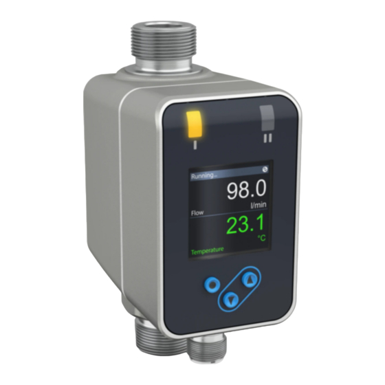
8 Operating and display elements 1 and 2: Switching status LEDs • LED 1 = switching status OUT1 (on if output 1 is switched) • LED 2 = switching status OUT2 (on if output 2 is switched) 3: TFT display •... -
Page 33: Menu
9 Menu 9.1 Process value display (RUN) It is possible to select three process value indications during operation: ► Press button [▲ ] or [▼]. > The display changes between the standard indication and two other views� > After 30 s, the device returns to the standard display� Running���... -
Page 34: 9�2 Main Menu
9.2 Main menu Process value display (RUN) FSP1 ImPS FEP1 ImPR FrP1 ASP2 DIn2 AEP2 rES, Info, OUT1, OUT2, CFG, TOTL, MEM, DIS, COLR, SIM Explanation of the parameters → 9.4 Submenu OUT1 and OUT2... -
Page 35: 9�3 Extended Functions
9.3 Extended functions EF Main menu Parameter Explanation and setting options - - - - Restore factory setting Info - - - - Info Display device information OUT1 Configuration output 1 OUT1 OUT2 Configuration output 2 OUT2 Configuration basic settings TOTL Display totaliser values TOTL... -
Page 36: 9�4 Submenu Out1 And Out2
9.4 Submenu OUT1 and OUT2 Main menu TEMP SEL1 FLOW Hno Hnc Fno Fnc ImP FRQ dir�F Info FSP1 OUT1 ImPS FEP1 OUT2 ImPR FrP1 OU On OFF FOU1 OUT1 TOTL TEMP SEL2 FLOW COLR Hno Hnc Fno Fnc In.D dir�F I ASP2 DIn2... - Page 37 Explanation submenu OUT1 Parameter Explanation and setting options SEL1 Standard measured variable for evaluation by OUT1: FLOW (volumetric flow) or TEMP (temperature) Output function for OUT1: • Volumetric flow: Hno, Hnc, Fno, Fnc, ImP, OFF, FRQ, dir�F • Temperature: Hno, Hnc, Fno, Fnc, OFF, FRQ Hno = switching signal with hysteresis function normally open Hnc = switching signal with hysteresis function normally closed Fno = switching signal with window function normally open...
- Page 38 Explanation submenu OUT2 Parameter Explanation and setting options SEL2 Standard measured variable for evaluation by OUT2: FLOW (volumetric flow) or TEMP (temperature) Output function for OUT2: • Volumetric flow: Hno, Hnc, Fno, Fnc, In.D, OFF, dir.F, I • Temperature: Hno, Hnc, Fno, Fnc, OFF, I Hno = switching signal with hysteresis function normally open Hnc = switching signal with hysteresis function normally closed Fno = switching signal with window function normally open...
-
Page 39: 9�5 Submenu Cfg And Totl
9.5 Submenu CFG and TOTL Main menu uni.F L/min /h m/s gal/min gal/h fl oz/min ft/s uni.T °C °F - - - Info - - - OUT1 PnP nPn OUT2 - - - Fdir TOTL rTo1 2 h 3 h 4 h 5 h ... rES.T rTo2 2 h 3 h 4 h 5 h ... - Page 40 Explanation submenu CFG Parameter Explanation and setting options uni�F Standard unit of measurement for volumetric flow: m/s, l/min*, m /h, gal/min, gal/h, fl oz/min, ft/s (*Type DN6: ml/min) uni�T Standard unit of measurement for temperature: °C or °F Measured value damping for switching output in seconds (only volumetric flow) Start-up delay in seconds (only volumetric flow) Output logic: PnP or nPn...
-
Page 41: 9�6 Submenu Mem And Dis
9.6 Submenu MEM and DIS Main menu Info Lo.F OUT1 Hi.F OUT2 Lo.T Hi.T TOTL LanG DE EN FR diS.L L2.Temp L2.Totl L3 COLR diS.U d1 d2 d3 diS.R 0 90 180 270 diS.B 25 50 75 100 OFF... - Page 42 Explanation submenu MEM Parameter Explanation and setting options Lo�F Min� value of the volumetric flow quantity measured in the process Hi�F Max� value of the volumetric flow quantity measured in the process Lo�T Min� value of the temperature measured in the process Hi�T Max�...
-
Page 43: 9�7 Submenu Colr And Sim
9.7 Submenu COLR and SIM Main menu coL.F bk/wh red green yellow r-cF G-cF Info - - - cFH�F OUT1 - - - cFL�F OUT2 coL.T bk/wh red green yellow r-cF G-cF - - - cFH�T TOTL - - - cFL�T coL.V bk/wh red green yellow... - Page 44 Explanation submenu COLR Parameter Explanation and setting options coL�F Colour of the characters in the display for the volumetric flow value cFH�F Upper limit of the colour change for volumetric flow measurement cFL�F Lower limit of the colour change for volumetric flow measurement coL�T Colour of the characters in the display for the temperature value cFH�T...
-
Page 45: Set
10 Set-up After power on and expiry of the power-on delay time of approx� 5 s the unit is in the Run mode (= normal operating mode)� It carries out its measurement and evaluation functions and generates output signals according to the set parameters�... -
Page 46: 11�1 Parameter Setting In General
11.1 Parameter setting in general 1� Change from the RUN mode to the main menu [●] 2� Select the requested parameter [▲] or [▼] 3� Change to the setting mode [●] [▲] or [▼] > 1 s 4� Modification of the parameter value 5�... -
Page 47: 11�1�4 Timeout
During operation: [�� ] is displayed if you try to change parameter values� Unlocking: ► Make sure that the unit is in the normal operating mode� ► Press [▲] and [▼] simultaneously for 10 s until [Reset menu lock] is displayed. Via the IO-Link interface the setting buttons can be locked with [Lock via system] so that you can no longer set parameters on the unit�... -
Page 48: 11�2�4 Frequency Signal Volumetric Flow Out1
11.2.4 Frequency signal volumetric flow OUT1 ► Select [SEL1] and set FLOW� Menu OUT1: ► Select [ou1] and select frequency signal: FRQ [SEL1] ► Select [FEP1] and set the upper volumetric flow value at which the [ou1] frequency set in FrP1 is provided� [FEP1] ►... -
Page 49: 11�3�3 Quantity Monitoring Via The Preset Counter Out1
11.3.3 Quantity monitoring via the preset counter OUT1 ► Select [SEL1] and set FLOW� Menu OUT1: ► Select [ou1] and set pulse output: ImP [SEL1] ► Select [ImPS] and set the volumetric flow quantity at which output 1 [ou1] switches� [ImPS] ►... -
Page 50: 11�3�8 Read Consumption Values
11.3.8 Read consumption values ► Select [Vol�1], [Vol�2] or [Vol�L] to display the respective meter reading: Menu TOTL: [Vol�1] - [Vol�1] = current meter reading totaliser 1 - [Vol�2] = current meter reading totaliser 2 [Vol�2] - [Vol�L] = current meter reading lifetime totaliser [Vol�L] 11.4 Settings for temperature monitoring 11.4.1 Limit monitoring OUT1 or OUT2 / hysteresis function... -
Page 51: 11�4�4 Analogue Signal Temperature Out2
11.4.4 Analogue signal temperature OUT2 ► Select [SEL2] and set TEMP� Menu OUT2: ► Select [ou2] and select analogue signal: I (4...20 mA) [SEL2] ► Select [ASP] and set the value at which 4 mA is provided� [ou2] ► Select [AEP] and set the value at which 20 mA is provided� [ASP2] [AEP2] 11.5 User settings (optional) -
Page 52: 11�5�3 Standard Unit Of Measurement For Volumetric Flow
11.5.3 Standard unit of measurement for volumetric flow ► Select [uni�F] and set the unit of measurement for standard display (→ Menu CFG: 11�5�2)� [uni�F] m/s ml/min l/min m /h gal/min gal/h fl oz/min ft/s DN15���DN25 The consumed quantity (meter reading) is automatically displayed in the unit of measurement providing the highest accuracy�... -
Page 53: 11�5�10 Colour Of The Characters In The Display
11.5.10 Colour of the characters in the display ► Select [coL�F] for volumetric flow or [coL�T] for temperature and set the Menu COLR: colour of the characters for the process value in the standard display: [coL�F] [coL�T] - bk/wh = permanently black/white [cFH�F] - yellow = permanently yellow [cFL�F]... -
Page 54: 11�5�11 Error Behaviour Of The Outputs
11.5.11 Error behaviour of the outputs ► Select [FOU1] and set the error behaviour for output 1: Menu OUT1: [FOU1] Switching output - On = Output 1 switches ON in case of an error Menu OUT2: - OFF = Output 1 switches OFF in case of an error [FOU2] - OU = Output 1 switches irrespective of the error as defined with the parameters... -
Page 55: 11�6 Diagnostic Functions
11.6 Diagnostic functions 11.6.1 Read min/max values ► Select [Lo�x] or [Hi�x] to display the highest or lowest process value Menu MEM: measured: [Lo�F] [Hi�F] - [Lo�F] = min� value of the volume flow measured in the process [Lo�T] - [Hi�F] = max� value of the volume flow measured in the process [Hi�T] - [Lo�T] = min�... -
Page 56: Troubleshooting
If a process value fails, the other process values are still available� Additional diagnostic functions are available via IO-Link → IODD interface description at www�krohne�com� ERROR ERROR Unit faulty / mal- FOU Replace device�... - Page 57 cr�OL Critical Detection zone FOU Check volumetric over exceeded flow range / tempera- limit ture range� cr�UL Critical Detection zone not FOU Check volumetric under reached flow range / tempera- limit ture range� Short Short circuit OUT1 Check switching OUT1 circuit and OUT2 outputs OUT1 and...
-
Page 58: Maintenance, Repair And Disposal
Lock via Setting buttons Unlock the unit via system locked via parameter IO-Link interface setting software, using the parameter parameter change setting software� rejected IO-Link IO-Link IO-Link function for Deactivate IO-Link OUT1 flash optical identification function� OUT2 of the unit active Display range / detection zone →... -
Page 59: Factory Setting
15 Factory setting Parameter Menu Factory setting User setting SEL1 OUT1 FLOW OUT1 SP1 / FH1 OUT1 20 % rP1 / FL1 OUT1 19 % FSP1 OUT1 FEP1 OUT1 100 % FrP1 OUT1 1000 Hz ImPS OUT1 Type: 0�001 l DN15 0�001 l DN20... - Page 60 Parameter Menu Factory setting User setting uni.F Type: ml/min DN15���25 l/min DN6���25 NPT gal/min uni.T Thread: G, Rc °C °F 0�6 s Type: 20 ml DN15���25 DN6���25 NPT MAW Fdir rTo1 TOTL rTo2 TOTL FPro1 TOTL FPro2 TOTL LanG diS.L diS.U diS.R diS.B...
- Page 61 KROHNE – Process instrumentation and measurement solutions Head Office KROHNE Messtechnik GmbH Ludwig-Krohne-Str. 5 47058 Duisburg (Germany) Tel.: +49 203 301 0 Fax: +49 203 301 10389 info@krohne.com www.krohne.com...
Need help?
Do you have a question about the AF-E 400 and is the answer not in the manual?
Questions and answers