Subscribe to Our Youtube Channel
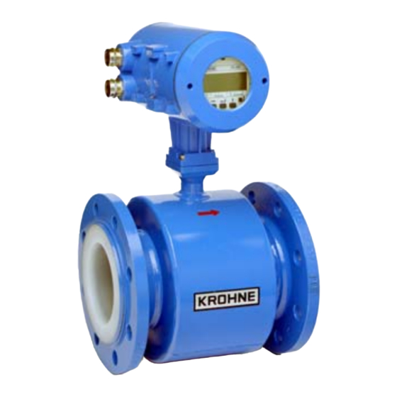
Summary of Contents for KROHNE IFC 090
- Page 1 © KROHNE 07/2000 Supplementary Installation and Operating Instructions IFC 090, IFC 090 i KROHNE Messtechnik GmbH & Co. KG · Ludwig-Krohne-Str. 5 D-47058 Duisburg Tel.: 0203-301 309 Fax: 0203-301389 · e-mail: krohne@krohne.de...
- Page 2 3. MENU SETTINGS FOR PROFIBUS-PA .....7 (SEE SECTION 4 IN THE INSTALLATION AND OPERATING INSTRUCTIONS) 4. TECHNICAL DATA, PROFIBUS IDENT-NO. F401 ....................7 KROHNE Messtechnik GmbH & Co. KG · Ludwig-Krohne-Str. 5 D-47058 Duisburg Tel.: 0203-301 309 Fax: 0203-301389 · e-mail: krohne@krohne.de...
-
Page 3: Items Included With Supply
Supplementary Documentation IFC 090, IFC 090 i with PROFIBUS-PA General These Instructions are supplementary to the “Installation and Operating Instructions IFC 090 K / F“ dated 12/96. The details given there, in particular the Safety Information, are valid and should be observed. These Supplementary Instructions provide only additional information for device operation and connection to a PROFIBUS-PA fieldbus. - Page 4 “PROFIBUS-PA networks”. 1.1 GSD All available GSD files of KROHNE devices – including those of the IFC 090, of course - are supplied together with each device. The GSD contains information that is needed for project planning of the PROFIBUS-DP/PA communication network.
- Page 5 If the device has been detected an error additional diagnostic information will be send to the master. The meaning of the additional information is described within the GSD file under UNIT_DIAG_BIT(i). KROHNE Messtechnik GmbH & Co. KG · Ludwig-Krohne-Str. 5 D-47058 Duisburg ...
-
Page 6: Electrical Connection
In “Ex“ systems an adequate equipotential bonding in the hazardous and non-hazardous location along the entire fieldbus installation is strongly recommended. Multiple grounding of the shield is also of advantage. Note: The use of twisted and shielded cables is strongly recommended, otherwise EMC protection of the IFC 090 cannot be assured. -
Page 7: Technical Data
(see Section 4 in the Installation and Operating Instructions) The following settings need to be made for operation of the IFC 090 on a PROFIBUS-PA network. Note that the address can be set by the service “set slave address” as well.


Need help?
Do you have a question about the IFC 090 and is the answer not in the manual?
Questions and answers