
Related Manuals for DAAB EP104

Summary of Contents for DAAB EP104
- Page 1 INSTRUCTION MANUAL DAAB AUTOMATIC CONTROL UNIT EP104 Edition 1 for EP104 version 4.08 FAAC Nordic AB BOX 125, SE-284 22 PERSTORP SWEDEN, +46 435 77 95 00, support@faac.se www.faac.se...
-
Page 2: Table Of Contents
INSTRUCTION MANUAL DAAB AUTOMATIC CONTROLL UNIT EP104 4.08 Contents EC Declaration of Conformity (original version) .....................6 Manufacturer ...............................6 Person authorised to compile the technical documentation .................6 General description and type designation ....................6 Declaration of performance ..........................6 Intended use of the construction product ....................6 System for the assessment and continuous verification of the performance of the construction product ..6... - Page 3 INSTRUCTION MANUAL DAAB AUTOMATIC CONTROLL UNIT EP104 4.08 Applications..............................22 Folding doors ..............................22 Load guard ..............................22 Safety edge ..............................22 Sliding doors/sliding gates ..........................22 Load guard ..............................22 Safety edge ..............................22 Up-and-over doors ............................22 Load guard ..............................22 Safety edge ..............................22 Hinged gates ..............................22 Load guard ..............................22...
- Page 4 INSTRUCTION MANUAL DAAB AUTOMATIC CONTROLL UNIT EP104 4.08 Pulse mode and hold-to-run mode ........................30 Selecting pulse mode or hold-to-run mode ....................30 Hold-to-run if there is an error in the safety edge or PHOTO input ..............30 Checking safety functions ..........................30 Setting electric motor braking .........................30 Programmable inputs, P channels ........................31...
- Page 5 INSTRUCTION MANUAL DAAB AUTOMATIC CONTROLL UNIT EP104 4.08 Instruction manual edition 1 for EP104 version 4.08...
-
Page 6: Ec Declaration Of Conformity (Original Version)
This declaration relates to automatic control unit EP1-4-1, EP104-2 specified in the condition in which it is placed on the market, and does not cover components added and/or modifications made thereafter. Nor does it relate to third-party equipment or to interfaces between third-party equipment and the equipment specified below and supplied by FAAC Nordic AB. -
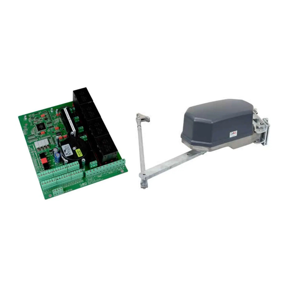
Page 7: Description Of The Ep104
• Disposal of electronic equipment EP104 is an electronic product, and as such it is classified as hazardous waste. All used electronic equipment must be sent for recycling by a company authorised under environmental legislation to handle hazardous waste including electronic equipment. -
Page 8: Safety
Follow the safety instructions of the equipment to be controlled by the control unit. • Safety classification FAAC Nordic AB has validated the safety circuits in the EP104 to performance level PL = c and Category 2 as defined by SS-EN ISO 13849-2:2008. -
Page 9: Operation
The condition of the enclosure, cables and installation must also be checked. This inspection must be carried out at least twice a year. Whenever work is carried out in or near the control unit, the power supply to the EP104 must be disconnected with a locked main switch. -
Page 10: Technical Specification
INSTRUCTION MANUAL DAAB AUTOMATIC CONTROLL UNIT EP104 4.08 Technical specification Dimensions (WxHxD) 190x224x60 mm. Power supply 3-phase or single-phase. Power supply 3x400V+N+PE, 3x230V+PE, 1x230V+N+PE, 3x400V+PE (requires an external transformer) Permitted voltage variation ±10% Frequency 50 Hz. Motor in 3-phase operation 3-phase asynchronous motor 0.18-1.5 kW. -
Page 11: Installing The Ep104 Pcb
INSTRUCTION MANUAL DAAB AUTOMATIC CONTROLL UNIT EP104 4.08 Installing the EP104 PCB If you are installing the PCB in a dedicated enclosure, you must follow the instructions below. Otherwise, the requirements of the applicable EU directive will not be met, FAAC Nordic's declaration of conformity will not be valid and the product will not be authorised for use. -
Page 12: Connections
INSTRUCTION MANUAL DAAB AUTOMATIC CONTROLL UNIT EP104 4.08 Connections • Safety The electrical connections may only be made by a qualified electrician, who accepts responsibility for ensuring that the electric connections have been carried out in accordance with the applicable standards and this instruction manual. - Page 13 For information about connecting to the frequency converter, see the instructions for add-in card DB409. If a symmetrical single-phase motor is used (as Supply 1x230V with neutral shown on the left) make the following changes. (symmetrical) EP104-1: Swap the cable at X12: L1-1 with X12: L1-CUR1. EP104 Supply to control board Supply to motors EP104-2: Remove the cable between X11: L2-1 and X4: L2-2.
-
Page 14: Connecting A Safety Edge
8.2 kΩ is six per input. Note that the impedance used for a safety edge must be checked and entered into the EP104 during commissioning, see Commissioning below. -
Page 15: Connecting An Encoder (Electronic Limit Switch)
• Connecting an encoder (electronic limit switch) EP104 supports DB405 type encoders. The encoder uses the same terminals as a conventional mechanical limit switch. The two diagrams below illustrate how to connect the encoder, and they also show which is the left and right motor from the point of view of the automatic control unit. -
Page 16: Configuring The Ep104
INSTRUCTION MANUAL DAAB AUTOMATIC CONTROLL UNIT EP104 4.08 Configuring the EP104 This section provides general instructions on how to change settings in the EP104. Remember to discharge any static charge in your body by always touching an earthed connection before starting installation. -
Page 17: Channel View Options C999
INSTRUCTION MANUAL DAAB AUTOMATIC CONTROLL UNIT EP104 4.08 • Channel view options C999 By entering different values in the view options channel, EP104 will switch between different sets of channels. After power on, C999 is shown as the first channel. -
Page 18: Signal Reference
The safety circuit, safety edge or limit switch must not be connected to, or used for, any other function. If signals from the EP104 are needed, a separate output card must be used. The connection instructions are the same for all types of application, but not all signals may be needed. -
Page 19: Indications
INSTRUCTION MANUAL DAAB AUTOMATIC CONTROLL UNIT EP104 4.08 • Indications To simplify commissioning and troubleshooting, LEDs are provided to indicate faults and the status of input signals, as shown in the table below. Colour Indication Active when Constant when control signal received, flashing when counting down for automatic... -
Page 20: Quick Guide For Commissioning Of Swing Gates
INSTRUCTION MANUAL DAAB AUTOMATIC CONTROLL UNIT EP104 4.08 Quick guide for commissioning of swing gates • Prerequisites The electrical installation is complete and drive units should be disengaged from the drive arm. Operate only one drive unit at a time and start with drive unit 1. The type of motor power in C202 is set to 0, 3x400V with neutral. Limit switches must be of encoder type. -
Page 21: Commissioning Of Drive Unit 2
INSTRUCTION MANUAL DAAB AUTOMATIC CONTROLL UNIT EP104 4.08 • Commissioning of drive unit 2 Preparation: Set C999 to 2. Open gate leaf 1 and set L001 to 0 to maintain the gate leaf in open position. Set C033 to 5, Service mode. - Page 22 Safety edge A safety edge for an up-and-over door must be set to send acknowledgements. This is a setting that is made in the EP104 by setting value 1 in channel C101 (C448 must be set to 0), safety edge acknowledgement. The safety edge is connected to SE.C1 and adjusted as described in the section on Safety edge.
- Page 23 The encoder works by detecting the position of the door, and acts as an intelligent limit switch. Using a magnetic proximity sensor, the EP104 calculates the precise position of the door. Limits for open and closed can be configured directly in the automatic control unit in degrees instead of physically changing limit switch cams in the motor winders.
- Page 24 INSTRUCTION MANUAL DAAB AUTOMATIC CONTROLL UNIT EP104 4.08 For a top-mounted motor winder, the motor is configured as for a right-mounted motor window. See below for the side- mounted motor winder. Note that if the motor winder is installed upside down, the sides must be swapped because the motor runs in the "wrong"...
- Page 25 • Check supply voltage to which the unit will be connected. • Check the required current – the maximum current for the 24 VDC of the EP104, terminal 33, is 300 mA, so an external transformer may be needed depending on what other equipment is connected.
- Page 26 INSTRUCTION MANUAL DAAB AUTOMATIC CONTROLL UNIT EP104 4.08 • Load guard The load guard can be used in two different ways. • With certified personal protection – fixed upper and lower limits and adjustable normal power • Without certified personal protection – an adjustable upper limit only The automatic control unit is initially configured for certified personal protection.
- Page 27 The integrated safety edge monitor in the automatic control unit performs a self test before the start of every movement. If any of the safety edges is faulty, the EP104 is stopped and an error is indicated. The principle is that the automatic control unit measures the impedance over the safety edge to ensure it matches a specified value.
- Page 28 The delay between activated safety edge and when the change of direction begins may be set in channel C493. Safety edge function in the closing movement On delivery and after a factory reset, the EP104 is configured to reverse to the fully open position when the safety edge is activated in the closing movement.
- Page 29 INSTRUCTION MANUAL DAAB AUTOMATIC CONTROLL UNIT EP104 4.08 • Input for photocell Terminal 29 can be used for photocell or vehicle loop via a control unit. The photocell can advantageously receive power from terminals 28 and 30, see Signal list section. The indication for this input is marked PHOTO, see section on Indications.
-
Page 30: Pulse Mode And Hold-To-Run Mode
INSTRUCTION MANUAL DAAB AUTOMATIC CONTROLL UNIT EP104 4.08 • Pulse mode and hold-to-run mode Hold-to-run mode means that the button has to be kept pressed to open or close – when the button is released, the motor stops. In pulse mode, pressing and releasing the button opens or closes the door automatically. Pulse mode can be configured for either direction. -
Page 31: Programmable Inputs, P Channels
INSTRUCTION MANUAL DAAB AUTOMATIC CONTROLL UNIT EP104 4.08 • Programmable inputs, P channels There are six programmable inputs available in the EP104. The instructions are identical for all six programmable inputs, apart from the channel number – input 1 has channel number P1nn, input 2 has channel number P2nn, etc. -
Page 32: Automatic Closing After Stop
INSTRUCTION MANUAL DAAB AUTOMATIC CONTROLL UNIT EP104 4.08 Automatic closing after stop All control signals except stop and power failure restart the countdown for automatic closing. This means that automatic closing is not affected in the event of a stop signal. This applies to conventional inputs and to programmable inputs. -
Page 33: Run-On Encoder
See the "Stop function" section under "Run-on time" below. When an encoder is used, the run-on times in C422, C423, C432 or C433 are not used. The EP104 instead calculates an angle that is displayed in L114, L115, L124 and L125. If this angle is too small, that is to say the door/gate stops too quickly, the run-on can be increased by configuring a value in F114, F115, F124 or F125. -
Page 34: Channel Reference
INSTRUCTION MANUAL DAAB AUTOMATIC CONTROLL UNIT EP104 4.08 Channel reference There are seven channel categories, each with its own letter and each handling different functions in the card. • C-channels: General readout and configuration channels. • d-channels: Channels relating to the DB402 vehicle detector. -
Page 35: General Configuration Channels
INSTRUCTION MANUAL DAAB AUTOMATIC CONTROLL UNIT EP104 4.08 General configuration channels Name Range Factory Setting Ref. page C033 Pulse/hold-to-run 0 - 5 Open and close with hold-to-run and load guard inactive Open with pulse and close with hold-to-run and load guard active... -
Page 36: Safety Edge
INSTRUCTION MANUAL DAAB AUTOMATIC CONTROLL UNIT EP104 4.08 Safety edge Name Range Factory Setting Ref. page C101 Safety edge acknowledgement SE.C1 0 – 1 Disabled Enabled C102 Function of output for external protection 0 – 4 Check disabled, open output, setting of C113, C123, C133, C143, C343, P643 is disabled. - Page 37 INSTRUCTION MANUAL DAAB AUTOMATIC CONTROLL UNIT EP104 4.08 Name Range Factory Setting Ref. page C121 Selects function for safety edge SE.C2 SE.C2 disabled Limits according to set value in C125 Fixed limits between 5 kohm and 15 kohm C122 Reverse/stop with activated safety edge SE.C2 1 –...
-
Page 38: Load Guard And Motor Settings
INSTRUCTION MANUAL DAAB AUTOMATIC CONTROLL UNIT EP104 4.08 Load guard and motor settings Name Range Factory Setting Ref. page C200 Load guard function 0 – 4 Disabled Service and troubleshooting only Reverse when closing, stop when opening Stop when closing and reverse when opening... -
Page 39: Photocell
INSTRUCTION MANUAL DAAB AUTOMATIC CONTROLL UNIT EP104 4.08 Photocell Name Range Factory Setting Ref. page C340 Safety function in closing movement 0 – 3 Disabled Reverse to fully open Stop with automatic restart of automatic closing Stop, wait for new control signal or time in C520 and thereafter automatic closing. -
Page 40: General Time Channels
INSTRUCTION MANUAL DAAB AUTOMATIC CONTROLL UNIT EP104 4.08 General time channels. Name Range Factory Setting Ref. page C401** Running time readout, motor 1 000-999 seconds C402** Running time readout, motor 2 000-999 seconds C403** Setting limited running time (Not used with... -
Page 41: Automatic Closing
INSTRUCTION MANUAL DAAB AUTOMATIC CONTROLL UNIT EP104 4.08 Automatic closing Name Range Factory Setting Ref. page C500 Automatic closing time 0.00-9.59 minutes 0.00 C501 Short automatic closing time 0.0-9.9 seconds C510 Time for LOOP1, LOOP2 and PHOTO closing 00-99 seconds... -
Page 42: Service Channels
INSTRUCTION MANUAL DAAB AUTOMATIC CONTROLL UNIT EP104 4.08 Service channels Name Range Factory Setting Ref. page C900 Service channel, for service personnel only Random 000-999 number C901 Service channel, for service personnel only 00-99 C902 Service channel, for service personnel only,... - Page 43 INSTRUCTION MANUAL DAAB AUTOMATIC CONTROLL UNIT EP104 4.08 Instruction manual edition 1 for EP104 version 4.08...
-
Page 44: Limit Switch, L-Channels
INSTRUCTION MANUAL DAAB AUTOMATIC CONTROLL UNIT EP104 4.08 • Limit switch, L-channels Name Range Factory Setting Ref. page L001 Choice of limit switch type for motor 1 Disabled Encoder Limit switch Time Hold-to-run without limit switches. NOTE! Only one half at a time can be run. C033 must be set to 5. - Page 45 INSTRUCTION MANUAL DAAB AUTOMATIC CONTROLL UNIT EP104 4.08 Name Range Factory Setting Ref. page L120* Position of motor 2, viewed from the motor side Disabled Left Right L121* Position readout, motor 2 000-360 degrees L122* Limit for open position, motor 2...
-
Page 46: Programmable Inputs, P Channels
INSTRUCTION MANUAL DAAB AUTOMATIC CONTROLL UNIT EP104 4.08 • Programmable inputs, P channels Programmable input 1 Name Range Factory Setting Ref. page P100 Channels in programmable input 1 0 - 1 Disabled Enabled P160 Control function Disabled Open Close Stop... -
Page 47: Programmable Input 2
INSTRUCTION MANUAL DAAB AUTOMATIC CONTROLL UNIT EP104 4.08 Programmable input 2 Name Range Factory Setting Ref. page P200 Channels in programmable input 2 0 - 1 Disabled Enabled P260 Control function Disabled Open Close Stop Open/close Open/stop/close P261 Type of control signal when activated... -
Page 48: Programmable Input 3
INSTRUCTION MANUAL DAAB AUTOMATIC CONTROLL UNIT EP104 4.08 Programmable input 3 Name Range Factory Setting Ref. page P300 Channels in programmable input 3 0 - 1 Disabled Enabled P360 Control function Disabled Open Close Stop Open/close Open/stop/close P361 Type of control signal when activated... -
Page 49: Programmable Input 4
INSTRUCTION MANUAL DAAB AUTOMATIC CONTROLL UNIT EP104 4.08 Programmable input 4 Name Range Factory Setting Ref. page P400 Channels in programmable input 4 0 - 1 Disabled Enabled P460 Control function Disabled Open Close Stop Open/close Open/stop/close P461 Type of control signal when activated... -
Page 50: Programmable Input 5
INSTRUCTION MANUAL DAAB AUTOMATIC CONTROLL UNIT EP104 4.08 Programmable input 5 Name Range Factory Setting Ref. page P500 Channels in programmable input 6 0 - 1 Disabled Activated (Only channels P560-P598 activated) Battery operation, only together with frequency converter (Channels P560-P598 inactivated) -
Page 51: Programmable Input 6
INSTRUCTION MANUAL DAAB AUTOMATIC CONTROLL UNIT EP104 4.08 Programmable input 6 Name Range Factory Setting Ref. page P600 Channels in programmable input 6 0 - 1 Disabled Activated (Only channels P660-P698 activated) Safety input (Only channels P640-P643 activated) P640 Safety function when input is activated 0 –... - Page 52 INSTRUCTION MANUAL DAAB AUTOMATIC CONTROLL UNIT EP104 4.08 P675 Opening via input after activation during set time, 0.0-9.9 seconds input will not open the barrier until it has been activated for the set time. P680 Keep opened 0 - 2...
-
Page 53: Error Messages
Grey background means that the automatic control unit must be restarted (power off) in order to reset the error message. Error Possible cause Meaning code Not an error code – indicates the type of EP104 EP-1 in use Not an error code – indicates the type of EP104 EP-2... - Page 54 INSTRUCTION MANUAL DAAB AUTOMATIC CONTROLL UNIT EP104 4.08 Error Possible cause Meaning code Motor is taking more than 1.5x motor current. Motor is E201 Motor protection triggered for motor 1 sluggish or stops. Faulty fuse? Phase failure in an incoming...
- Page 55 INSTRUCTION MANUAL DAAB AUTOMATIC CONTROLL UNIT EP104 4.08 Error Possible cause Meaning code E912 Incorrect checksum in flash memory Contact FAAC Nordic AB. E913 Memory error in RAM Contact FAAC Nordic AB. E914 Memory error in EEPROM Contact FAAC Nordic AB.
-
Page 56: Resetting/Replacing Tripped Fuses
INSTRUCTION MANUAL DAAB AUTOMATIC CONTROLL UNIT EP104 4.08 Troubleshooting At each service, please check all the functions described in the relevant section on commissioning. Problem Possible cause, tip Error message in the display (Ennn) See the section above on error messages. -
Page 57: Notes
INSTRUCTION MANUAL DAAB AUTOMATIC CONTROLL UNIT EP104 4.08 Notes: Instruction manual edition 1 for EP104 version 4.08... -
Page 58: Notes
INSTRUCTION MANUAL DAAB AUTOMATIC CONTROLL UNIT EP104 4.08 Notes: Instruction manual edition 1 for EP104 version 4.08... -
Page 59: Notes
INSTRUCTION MANUAL DAAB AUTOMATIC CONTROLL UNIT EP104 4.08 Notes: Instruction manual edition 1 for EP104 version 4.08...
Need help?
Do you have a question about the EP104 and is the answer not in the manual?
Questions and answers