
Related Manuals for MICRO-EPSILON eddyNCDT SGS 4701


Summary of Contents for MICRO-EPSILON eddyNCDT SGS 4701
- Page 1 Instruction Manual eddyNCDT SGS 4701 EMU04(10x) EMU04(12x) EMU04(11x) EMU04(13x) EMU04(14x) EMU04(16x) EMU04(15x) EMU04(17x)
- Page 2 Digital Eddy-Current Measuring System for Spindle Growth System MICRO-EPSILON MESSTECHNIK GmbH & Co. KG Königbacher Strasse 15 94496 Ortenburg / Germany Tel. +49 (0) 8542 / 168-0 Fax +49 (0) 8542 / 168-90 e-mail info@micro-epsilon.de www.micro-epsilon.com Certified acc. to DIN EN ISO 9001: 2008...
-
Page 3: Table Of Contents
Installation and Assembly ...................... 13 Precautions ..............................13 Sensor ................................13 Sensor Cable ..............................15 Controller ............................... 17 Connecting the Measuring System ....................... 18 Operation ..........................19 Warranty ..........................19 Service, Repair ........................20 Decommissioning, Disposal ....................20 eddyNCDT SGS 4701... - Page 4 Appendix Clamping Flange Controller....................21 Tool Sensor Cable ........................22 Optional Accessories ......................22 Notes for Electrostatic Discharge ..................23 eddyNCDT SGS 4701...
-
Page 5: Safety
> Damage to or destruction of the controller and/or sensor Avoid shock and vibration to the sensor and controller. > Damage to or destruction of the controller and/or sensor Protect the sensor cable against damage > Failure of the measuring device eddyNCDT SGS 4701 Page 5... -
Page 6: Notes On Ce Identification
Products which carry the CE mark satisfy the requirements of the quoted EU directives and the standards (EN) listed therein. The EC declaration of conformity is kept available according to EC regulation, article 10 by the authorities responsible at MICRO-EPSILON Messtechnik GmbH & Co. KG Königbacher Straße 15 94496 Ortenburg / Germany The measuring system is designed for the use in industry and satisfies the requirements. -
Page 7: Proper Environment
0 ... +90 °C (+32 ... +194 °F) ƒ Controller +10 ... +70 °C (+50 ... +158 °F) - Storage temperature: 0 ... +70 °C (+32 ... +158 °F) - Humidity: 5 - 95 % (non-condensing) - Ambient pressure: Atmospheric pressure eddyNCDT SGS 4701 Page 7... -
Page 8: System Description
The eddyNCDT SGS 4701 conditions the sensor signals user-fairly at a frequency response of 2,000 Hz. Thus a so-called spindle monitoring is also still possible at numbers of revolutions up to 120,000 rpm. The spindle growth itself can be detected at even higher numbers of revolutions. -
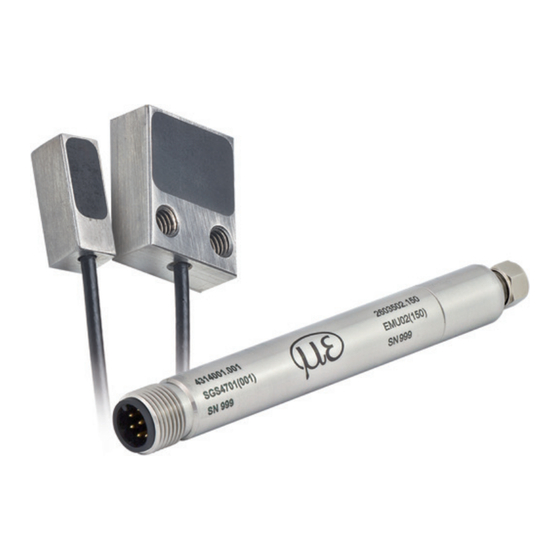
Page 9: Structure Of The Measuring System
Due to its compact size, the measurement technology (paired electronics and sensor) is fully integrated into the spindle head. Compared to its predecessor model, the eddyNCDT SGS 4311, interchangeability between sensor and electronics is unnecessary and no longer possible. eddyNCDT SGS 4701 Page 9... -
Page 10: Glossary
End of measuring range (start of measuring range + measuring range) Maximum distance between sensor front and target Measuring range U [V] U [V] Displace- Temp. ment 600 µm 90 °C Target Sensor Measuring range eddyNCDT SGS 4701 Page 10... -
Page 11: Technical Data
12 x 10 x 4.5 mm³ Dimensions EMU04(12x) 10 x 4 x 4 mm³ Diameter Ø 1.13 mm Length 1000 mm (400 - 1500 mm on request) Sensor cable Min. bending radius 12 mm Coating eddyNCDT SGS 4701 Page 11... -
Page 12: Delivery
In case of damage or missing parts, please contact the manufacturer or supplier. You will find optional accessories in appendix, see Chap. Storage Storage temperature: 0 ... +70 °C (+32 ... +158 °F) Humidity: 5 - 95 % (non-condensing) eddyNCDT SGS 4701 Page 12... -
Page 13: Installation And Assembly
Sensor coil EMU04(17x) EMU04(15x) -0 03 4.5 ±0.05 (0.18 ±0.05) -0 03 -0 005 -0 027 (.16 -0 0011 -0 0002 (0.39 -0 001 Fig. 3 Dimensional drawing sensor, dimensions in mm (inches), not to scale eddyNCDT SGS 4701 Page 13... - Page 14 6 mm or greater for an eddy-current sensor. Optional Sensor sensors are available with a minimum area diameter of 3.5 mm. If you underrun the minimum measuring area nor reproducibly measurements are possible. Fig. 5 Minimum measuring area for eddy-current sensor eddyNCDT SGS 4701 Page 14...
-
Page 15: Sensor Cable
Lay the sensor cable in such a way that no sharp-edged or heavy objects can affect the cable sheath. Do not kink the cable. Details to the sensor cable are listed in the appendix, see Chap. Sensor Bending radius: Controller R ≥ 12 mm Fig. 7 Minimum bending radius for sensor cable eddyNCDT SGS 4701 Page 15... - Page 16 Connect the sensor cable to the female con- Solder the sensor cable to the connection nector. board. Close the cable gland. Push the sensor cap onto the controller housing until it snaps in place. Fig. 8 Connection sensor cable eddyNCDT SGS 4701 Page 16...
-
Page 17: Controller
(.47 dia. -.004) WS 8 Fig. 9 Dimensional drawing of controller, dimensions in mm (inches), not to scale The controller is mounted laminar with a circumferential clamping on housing or with an optional clamping flange. eddyNCDT SGS 4701 Page 17... -
Page 18: Connecting The Measuring System
Temperature signal yellow (0.5 ... +9.5 V) at 0 ... +90 °C gray 8-pin. male connector 6, 7 internally assigned pink, blue controller, view on pin side Screen Housing Fig. 10 Pin assignment for signal output eddyNCDT SGS 4701 Page 18... -
Page 19: Operation
The warranty period lasts 12 months following the day of shipment. Defective parts, except wear parts, will be repaired or replaced free of charge within this period if you return the device free of cost to MICRO-EPSILON. This warranty does not apply to damage resulting from abuse of the equipment and devices, from forceful handling or installation of the devices or from repair or modifications performed by third parties. -
Page 20: Service, Repair
Fax +49 (0) 8542 / 168-90 eltrotec@micro-epsilon.de www.micro-epsilon.com Decommissioning, Disposal Disconnect the power supply and output cable on the controller. Disconnect the sensor cable between sensor and controller. Do the disposal according to the legal regulations (see directive 2002/96/EC). eddyNCDT SGS 4701 Page 20... -
Page 21: Appendix
Appendix| Clamping Flange Controller Appendix Clamping Flange Controller 20 (.79) 15 (.59) Dimensions in mm (inches), not to scale eddyNCDT SGS 4701 Seite 21... -
Page 22: A 2 Tool Sensor Cable
Dimensions in mm (inches), not to scale You will find details for the tool to the sensor cable miniature connector under: http://www.radiall.com/rf-coaxial-connectors/mml-extraction-tool-h2-0-h2-5.html Optional Accessories Power supply and output cable, 10 m long, with 8-pin. female connector respectively with PC4701-10 open ends eddyNCDT SGS 4701 Seite 22... -
Page 23: A 4 Notes For Electrostatic Discharge
- EN 61340-5-1 Protection of electronic components against electrostatic phenomenon - General require- ments - EN 61340-5-2 Protection of electronic components against electrostatic phenomenon - User manual - VDE publications 71 Electrostatics, reasons, effects, protective measures eddyNCDT SGS 4701 Seite 23... - Page 24 MICRO-EPSILON MESSTECHNIK GmbH & Co. KG X9751318-A031115HDR Königbacher Str. 15 · 94496 Ortenburg / Germany MICRO-EPSILON MESSTECHNIK Tel. +49 (0) 8542 / 168-0 · Fax +49 (0) 8542 / 168-90 info@micro-epsilon.de · www.micro-epsilon.com *X9751318-A03*...
Need help?
Do you have a question about the eddyNCDT SGS 4701 and is the answer not in the manual?
Questions and answers