Table of Contents
Advertisement
Quick Links
Advertisement
Table of Contents

Related Manuals for Datalogic DP1100 Series


Summary of Contents for Datalogic DP1100 Series
- Page 1 DP1100 Installation Manual...
- Page 2 DP1100 INSTALLATION MANUAL...
- Page 3 Product names mentioned herein are for identification purposes only and may be trademarks and or registered trademarks of their respective companies. Datalogic reserves the right to make modifications and improvements without prior notification. © - 1996, 1998 Datalogic S.p.A. 821000002 (Rev. B)
-
Page 4: Table Of Contents
CONTENTS General View..................v SAFETY PRECAUTIONS ..............vi GENERAL FEATURES ..............1.1 Introduction..................1.1 Available Models ................1.1 Description ..................1.2 1.3.1 Display....................1.3 1.3.2 Keypad .....................1.3 1.3.3 LEDs....................1.4 1.3.4 On/off Switch..................1.4 1.3.5 Removable Glands Panel ..............1.5 1.3.6 Communication Interfaces ...............1.5 1.3.7 Inputs....................1.5 1.3.8 Outputs.....................1.6 INSTALLATION ................2.1 Package Contents................2.1 Guide to Installation................2.1 Opening the Device................2.2... - Page 5 2.9.2 Outputs...................2.25 2.10 Typical Layouts ................2.27 2.10.1 Pass Through.................2.29 2.10.2 Local Echo..................2.30 2.10.3 Master-Slave (Special software versions only) ......2.31 MAINTENANCE................3.1 Replacing the Protection Fuse ............3.1 TECHNICAL FEATURES ..............4.1...
-
Page 6: General View
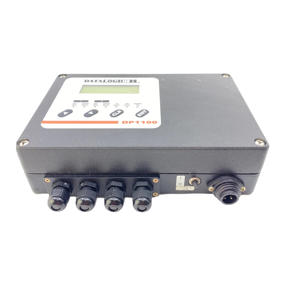
DP1100 General View Figure A Power supply connector LEDs On/off switch LCD display Scan head 2 connector Glands panel (only for 2 scan head models) Keypad Scan head 1 connector... -
Page 7: Safety Precautions
SAFETY PRECAUTIONS This product conforms to the applicable requirements contained in the European Standard for electrical safety EN-60950 at the date of manufacture. This symbol refers to operations that must be performed by qualified personnel only. Example: opening the device. This symbol refers to operations where there is danger of electrical shock. -
Page 8: General Features
Programmability If your requirements are not met by the Standard Application Program, Custom Application Programs can be developed by your local Datalogic distributor. AVAILABLE MODELS The DP1100 is available in versions that differ in regard to the following parameters: •... -
Page 9: Description
For more details refer to your local Datalogic distributor. IP65 protection class can be obtained to make DP1100 particularly suitable for industrial environments where high protection against harsh external conditions is required. For more details refer to your local Datalogic distributor. 1.2 - General features... -
Page 10: Display
DATALOGIC DP1100 The DP1100 is contained in a rugged aluminum housing; the mechanical dimensions are 240 x 200 x 66 mm and it weighs about 2.8 Kg. 1.3.1 Display The DP1100 is equipped with a 20 character x 4 line backlit LCD. The LCD is used by the Standard Application Program to display programming and error messages, to view current configuration parameters and user menus. -
Page 11: Leds
DP1100 DATALOGIC 1.3.3 LEDs The 7 colored LEDs on the DP1100 front panel are shown in the following figure: GOOD GOOD POWER TRIG READ TRIG READ DATA DATA Figure 1.1 - DP1100 LEDs The first two LEDs refer to scan head 1 connected to the decoder. The next two LEDs refer to scan head 2 for H2 models. -
Page 12: Removable Glands Panel
DATALOGIC DP1100 1.3.5 Removable Glands Panel To make installation and replacement easier, the DP1100 is made up of two parts: 1) the body of the device with all standard electronic components and optional boards 2) the removable panel housing the glands for all external communication cables This panel houses four glands for I/O and serial interface connections. -
Page 13: Outputs
DP1100 DATALOGIC 1.3.8 Outputs Three outputs are present to signal if the barcode reading has been performed or not. They have different meanings depending on the model used. H1 models: • NO READ output • RIGHT output • WRONG output (Code Verifier and PCS) The NO READ output activates when the code signalled by the presence sensor is not decoded. -
Page 14: Installation
DATALOGIC DP1100 INSTALLATION 2.1 PACKAGE CONTENTS Verify that the DP1100 reader and all the parts supplied with the equipment are present and intact when opening the packaging; the list of parts includes: 1) DP1100 decoder 2) Installation manual 3) DP1100 configuration program disk... -
Page 15: Opening The Device
DP1100 DATALOGIC 1) Open the decoder to select the main serial interface type as required (see paragraph 2.3). 2) Provide correct system cabling according to the signals necessary (see par. 2.5, the applicable sub-paragraphs under 2.6, par. 2.7, 2.8, and 2.9). - Page 16 DATALOGIC DP1100 • Mount the decoder on a panel or a wall. (Par. 2.4) You have to remove the top panel to perform all these operations; you also have to remove the glands panel to change cable connections. WARNING The decoder must be disconnected from the power supply during this operation.
-
Page 17: Main Serial Interface Selection
DP1100 DATALOGIC 2.3.1 Main serial interface selection One of the following interface types can be selected to connect the main interface of the DP1100 to the host computer: EIA RS232 20 mA CURRENT LOOP EIA RS485 POLLED EIA RS485 NON POLLED... -
Page 18: Removing And Wiring The Glands Panel
DATALOGIC DP1100 2.3.2 Removing and wiring the glands panel After opening the decoder you must remove the panel housing the glands to connect or change the internal cabling to the DP1100. To connect an external cable to the DP1100, proceed as follows: Turn the DP1100 off. - Page 19 DP1100 DATALOGIC Figure 2.4 - Inserting the wire Figure 2.5 - DP1100 view Figure 2.6 - Terminal block connector and base 2.6 - Installation...
-
Page 20: Mechanical Installation
DATALOGIC DP1100 2.4 MECHANICAL INSTALLATION 2.4.1 Overall Dimensions The figure below gives the overall dimensions of the decoder and its relative mounting holes and may be used for its installation. Figure 2.7- Overall dimensions Installation – 2.7... -
Page 21: Mounting Dp1100
DP1100 DATALOGIC 2.4.2 Mounting DP1100 DP1100 can be mounted on a wall or a panel. To do this: 1) Open the decoder as described in paragraph 2.3. If necessary, using the two mounting holes inside the DP1100 as a pattern, mark the panel or the wall with an appropriate object and then drill two pilot holes in the panel or in the wall. -
Page 22: Power Supply Connections
DATALOGIC DP1100 POWER SUPPLY CONNECTIONS All versions of DP1100 are powered from the AC mains (see paragraph 1.2). A connection cable terminated with the 4 pin male connector provided with the package is used. A.C. CONNECTION LINE NEUTRAL 4 PIN MALE CONNECTOR Figure 2.9 - Power supply connector - Cable side view... -
Page 23: Pinout
DP1100 DATALOGIC Pinout The terminals of the internal connectors are numbered as illustrated in figure 2.10 depending on the model: H1 models H2 models 1 SHIELD 1 SHIELD 2 C.L. GND 2 C.L. GND 3 DRVCLOUT 3 DRVCLOUT 4 DRVCLIN... -
Page 24: Grounding Rules
DATALOGIC DP1100 Grounding Rules Shielding the communication cable is an effective way to protect against capacitive conduction and radiated interference, while the effect against noise due to inductive coupling is small. In any case, the shielding effect occurs only if the shield is grounded; otherwise the entire voltage of the shielded material will be floating and will not give protection against electrical noise. -
Page 25: Rs232 Interface
DP1100 DATALOGIC RS232 Interface The serial interface is used in this case for point to point connections; it handles communication with the host computer and allows both transmission of code data and the configuration of the decoder. The terminals of the external cable must be connected to the following pins of connector J1 (see figure 2.10) for RS232 interface connection:... -
Page 26: Rs485 Non Polled Interface
DATALOGIC DP1100 Figure 2.13 - RS232 control signals The RTS232 and CTS232 signals control data transmission and synchronize the connected devices. If the RTS/CTS handshaking protocol is enabled, the DP1100 activates the RTS232 output to indicate a message is to be transmitted. The receiving unit activates the CTS232 input to enable the transmission. -
Page 27: Rs485 Polled Interface
DP1100 DATALOGIC DP1100 USER INTERFACE GND485 RS485REF TXRX485+ RX485 TXRX485- RX485+ TX485 RX485- MAXIMUM LENGTH: 1200 m Figure 2.14 - RS485 NON POLLED connections To select this interface type, follow the instructions in paragraph 2.3.1 "Main Serial Interface Selection" . - Page 28 DATALOGIC DP1100 For this interface type, the multidrop address must also be set on the DIP switch as shown in the figure below. Refer to paragraph 2.3 for details on how to open the DP1100. Record this information for further setup of the multidrop line.
- Page 29 DP1100 DATALOGIC Example address selections for DP1100 Multidrop connections: Address 1 Address 9 Address 20 5 4 3 2 1 5 4 3 2 1 5 4 3 2 1 Figure 2.17 - DP1100 multidrop address selections The following figure shows a multidrop configuration with DP1100 decoders and a multiplexer connected.
-
Page 30: Ma Current Loop Interface
DATALOGIC DP1100 20 mA Current Loop Interface The DP1100 has two current generators (one for transmission and one for reception), allowing active and passive type connections. The terminals of the external cable must be connected to the following pins of connector J1 (see figure 2.10) for 20 mA Current Loop communications: 20 mA C.L. -
Page 31: Auxiliary Rs232 Interface Connections
DP1100 DATALOGIC DP1100 USER INTERFACE C.L. OUT+ C.L. OUT- C.L. IN+ C.L. IN- MAXIMUM LENGTH: 300 m Figure 2.20 - 20 mA C.L. passive connections To select this interface type, follow the instructions in paragraph 2.3.1 "Main Serial Interface Selection". -
Page 32: Barcode Reader Connections
DATALOGIC DP1100 The terminals of the external cable must be connected to the following pins of connector J1 (see figure 2.10) to connect the RS232 auxiliary interface: RS232 auxiliary connection Name Function RXAUX Auxiliary Input CTSAUX Auxiliary Handshake RTSAUX Auxiliary Handshake... - Page 33 DP1100 DATALOGIC Figure 2.22 - 15 pin female connector type D The following pins are available: Barcode reader connector pinout Name Function Ground Operating Voltage - VIDEO Complementary Video Signal + VIDEO Video Signal Representing Code + SCAN Scan Start...
-
Page 34: I/O Connections
DATALOGIC DP1100 I/O CONNECTIONS 2.9.1 Inputs PS1 and PS1AUX presence sensor inputs refer to scan head 1, while PS2 and PS2AUX presence sensor inputs refer to scan head 2 (H2 models only). For more details refer to paragraph 1.3.7. The signals relative to these sensors must be connected to the decoder via the proper internal connectors J2, J3 and J4 (see figure 2.10), respecting the... - Page 35 DP1100 DATALOGIC A PRESENCE SENSOR input can be driven by sensors with NPN or PNP output and is optoisolated to assure maximum disturbance immunity. The electrical features are: maximum voltage applicable at input: 30 V. maximum current: 20 mA. VDC1 and VDC2 and their relative ground references (GND1, GND2) supply...
- Page 36 DATALOGIC DP1100 For H2 models, when 2 scanners are connected to DP1100 in a Single Reading layout, the presence sensors inputs should be connected in parallel to a single NPN sensor. These connections are provided in the following figure. DP1100...
- Page 37 DP1100 DATALOGIC AUXILIARY PRESENCE SENSOR DP1100 14, (10) 11, (7) PSAUX+ Signal PSAUX- 12, (8) 13, (9) Ground CONNECTION WITH NPN SENSOR AUXILIARY PRESENCE SENSOR DP1100 14, (10) Signal 11, (7) PSAUX+ PSAUX- 12, (8) 13, (9) Ground CONNECTION WITH PNP SENSOR...
-
Page 38: Outputs
DATALOGIC DP1100 2.9.2 Outputs The following pins are present on connector J4 (see figure 2.10) of the decoder depending on the model: Connector J4 for H1 models Name Function WRONG+ Wrong Read Output (+) WRONG- Wrong Read Output (-) RIGHT+... - Page 39 DP1100 DATALOGIC DP1100 USER INTERFACE Vext 1,3,5 SIGNAL+ 2,4,6 SIGNAL- Figure 2.26 - Open collector output connection DP1100 USER INTERFACE Vext 1,3,5 SIGNAL+ 2,4,6 SIGNAL- Figure 2.27 - Open emitter output connection In the figures above, SIGNAL+ and SIGNAL- are used to refer to the corresponding No Read, Right or Wrong output signals, see table on the previous page.
-
Page 40: Typical Layouts
DATALOGIC DP1100 2.10 TYPICAL LAYOUTS The DP1100 decoder was specifically designed for industrial applications. A typical use is real time identification of moving objects on conveyors. The decoder generally activates the scanner(s) when signalled by a photoelectric sensor used as a code presence sensor when an object enters the barcode reader reading zone. - Page 41 DP1100 DATALOGIC Host DP1100 LS4100 LS4100 Figure 2.30 - DP1100 (H2) with 2 scanners in single reading mode Host DP1100 LS4100 LS4100 Figure 2.31- DP1100 (H2) with 2 scanners in single reading mode 2.28 - Installation...
-
Page 42: Pass Through
DATALOGIC DP1100 Host DP1100 LS4100 LS4100 Figure 2.32 - DP1100 (H2) with 2 scanners in twin reading mode 2.10.1 Pass Through Pass Through mode allows two or more DP1100s to be connected to a single external serial interface by chaining the Auxiliary and Main interfaces towards the Host. -
Page 43: Local Echo
DP1100 DATALOGIC DP1100 DP1100 LS4100 LS4100 Main serial interface Auxiliary serial interface Presence sensor HOST Figure 2.33 - Pass through layout 2.10.2 Local Echo For H1 models, in local echo mode data is transmitted on the auxiliary interface as well as on the main interface. -
Page 44: Master-Slave (Special Software Versions Only)
DATALOGIC DP1100 2.10.3 Master-Slave (Special software versions only) Upon request, special versions of the DP1100 can implement a Master-Slave layout for data collection from several scanners to build a multi-sided reading system. There can be one Master and up to 9 Slaves connected together. - Page 45 DP1100 DATALOGIC This page is intentionally left blank. 2.32 - Installation...
-
Page 46: Maintenance
DATALOGIC DP1100 3 MAINTENANCE REPLACING THE PROTECTION FUSE All the internal circuits of the DP1100 are protected by a fuse on the input power line. The decoder must be opened to change the fuse. WARNING The decoder must be disconnected from the power supply during this operation. - Page 47 DP1100 DATALOGIC PROTECTION SHIELD GROUND CABLE SCREW Figure 3.1 - Protection shield position PROTECTION FUSE Figure 3.2 - Fuse position 3.2 - Maintenance...
-
Page 48: Technical Features
DATALOGIC DP1100 4 TECHNICAL FEATURES DP1100 H1 DP1100 H2 ELECTRICAL FEATURES INPUT POWER 230 Vac 50/60Hz ± 20% (184-276V) Supply voltage 110 Vac 50/60Hz ± 20% (88-132V) Supply voltage Power consumption max. 35 VA SERIAL INTERFACES MAIN RS232, RS485 Non Polled, RS485 Polled, 20 mA C. - Page 49 DP1100 DATALOGIC SOFTWARE FEATURES READABLE CODE SYMBOLOGIES Up to 22 readable barcode symbologies including: • • Interleaved 2/5 EAN/UPC • (including Add-on 2 and Add-on 5) Code 39 (Standard and Full ASCII) • • Code 128 Codabar • • EAN 128...
Need help?
Do you have a question about the DP1100 Series and is the answer not in the manual?
Questions and answers