Table of Contents
Advertisement
Quick Links
Advertisement
Table of Contents

Related Manuals for Datalogic DP1200


Summary of Contents for Datalogic DP1200
- Page 1 DP1200 Installation Manual...
- Page 3 DP1200 INSTALLATION MANUAL...
- Page 4 ALL RIGHTS RESERVED Datalogic reserves the right to make modifications and improvements without prior notification. Datalogic shall not be liable for technical or editorial errors or omissions contained herein, nor for incidental or consequential damages resulting from the use of this material.
-
Page 5: Table Of Contents
CONTENTS GUIDE TO INSTALLATION .................iv GENERAL VIEW ..................v SAFETY PRECAUTIONS................vii Power Supply....................vii GENERAL FEATURES ................1 Introduction ....................1 Description ....................2 Accessories....................2 INSTALLATION.................... 3 Package Contents..................3 Opening the Device ..................4 Mechanical Installation.................. 5 Electrical Connections................... 7 2.4.1 System Wiring.................... -
Page 6: Guide To Installation
GUIDE TO INSTALLATION The following can be used as a checklist to verify all of the steps necessary for complete installation of the DP1200 decoder. 1) Read all information in the section "Safety Precautions" at the beginning of this manual. -
Page 7: General View
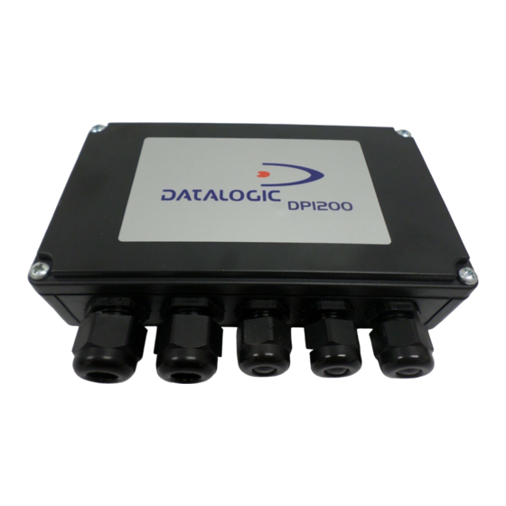
GENERAL VIEW DP1200 Figure A 15-pin reader connector Cover screws (4) Compression connector panel... - Page 8 DP1200 Figure B Mounting screw holes (2) Main interface selectors Spring clamp terminal blocks Auxiliary interface connector LEDs Power switch (ON/OFF) Multidrop address switches Reader connector Termination resistance switch...
-
Page 9: Safety Precautions
SAFETY PRECAUTIONS POWER SUPPLY ATTENTION: READ THIS INFORMATION BEFORE INSTALLING THE PRODUCT - This product is intended to be installed by Qualified Personnel only. This device is intended to be supplied by an NEC Class 2 power source, rated 10-30 V, minimum 0.50 A. - Page 10 viii...
-
Page 11: General Features
GENERAL FEATURES GENERAL FEATURES INTRODUCTION The DP1200 is an high performance industrial decoder for high speed barcode readers combining real time decoding and easy installation in a very flexible solution. Standard Application Program A Standard Application Program is factory-loaded onto the DP1200. This program controls barcode reading, serial port interfacing, data formatting and many other operating and control parameters. -
Page 12: Description
• Supply voltage from 10 to 30 Vdc DP1200 mechanical dimensions are 167 x 115 x 40 mm (6.57 x 4.52 x 1.57 in.). It weighs about 310 g. (10.93 oz). Electrical connection is provided through spring clamp terminal blocks inside the decoder. -
Page 13: Installation
INSTALLATION INSTALLATION PACKAGE CONTENTS Verify that the DP1200 decoder and all the parts supplied with the equipment are present and intact when opening the packaging; the list of parts includes: • DP1200 decoder • Installation manual • DP1200 communication and utility program disk •... -
Page 14: Opening The Device
DP1200 OPENING THE DEVICE Before installing the DP1200 or during normal maintenance, it is necessary to open it by unscrewing the four cover screws as shown in the figure below: The decoder must be disconnected from the power supply during this operation. -
Page 15: Mechanical Installation
INSTALLATION MECHANICAL INSTALLATION The diagram below gives the overall dimensions of the decoder and may be used for its installation. ∅ ∅ 0.14 0.19 0.19 5.91 3.54 4.53 6.57 inch Figure 3 - Overall dimensions... - Page 16 DP1200 DP1200 can be installed to operate in different positions. The two screw holes inside the housing of the decoder are for mechanical fixture (Figure 4). To do this: Open the DP1200 by unscrewing the 4 cover screws. If necessary, using the two mounting holes inside the decoder as a pattern, mark the panel with an appropriate object and then drill two small pilot holes in the panel.
-
Page 17: Electrical Connections
ELECTRICAL CONNECTIONS 2.4.1 System Wiring The connection and wiring procedure for DP1200 is described as follows: Open the DP1200 as described in paragraph 2.2. Verify that the DP1200 power switch is off (see Figure 6). Unscrew the compression connectors and pass all the system cables through them in the device housing. - Page 18 The signals on pins 18, 19 and 20 are repeated on pins 21, 22 and 23 to facilitate network connections (i.e. Multiplexer connections using the RS485 half-duplex Interface). In this way the network bus can enter and exit the DP1200 from different spring clamps but be physically connected together.
-
Page 19: Power Supply
CAUTION Switch ON the DP1200 power switch (see Figure 6). Close the DP1200 using the 4 cover screws making sure the rubber seal is fitted correctly between the parts of the housing. Connect the reader to the 15-pin connector on the left side of the DP1200 housing. - Page 20 The power must be between 10 and 30 Vdc only. There is a current peak during power on that depends on the type of barcode reader connected. If DP1200 is connected to the Datalogic LS6100 barcode reader, the minimum supply voltage is 12 Vdc.
-
Page 21: Main Interface Selection
INSTALLATION 2.4.3 Main Interface Selection The user can select one of the following four serial interface types: RS232 RS485 FULL-DUPLEX RS485 HALF-DUPLEX 20 mA CURRENT LOOP The relative signals are available on the spring clamp connector. To select the interface type, position the jumper block as indicated in the figure below: RS232 Half Duplex... - Page 22 DP1200 The relative parameters of the main serial interface (baud rate, data bits, etc.) are selected via software either using the WinHost utility program or Host Mode programming. For more details refer to the section "Main Interface Menu" in the WinHost Help On Line.
- Page 23 The RTS232 and CTS232 signals control data transmission and synchronize the connected devices. If the RTS/CTS handshaking protocol is enabled, the DP1200 activates the RTS232 output to indicate a message is to be transmitted. The receiving unit activates the CTS232 input to enable the transmission.
- Page 24 DP1200 RS485 Full-Duplex Interface The optocoupled RS485 full-duplex (5 wires + shield) interface is used for non-polled communication protocols in point-to-point connections over longer distances (max 1200 m / 3940 ft) than those acceptable for RS232 communications or in electrically noisy environments.
- Page 25 The optocoupled RS485 half-duplex (3 wires + shield) interface is used for polled communication protocols. It can be used in a master/slave layout or for Multidrop connections with a Datalogic Multiplexer, (see par. 2.5.4 and 2.5.5) exploiting a proprietary protocol based on polled mode called MUX32 protocol, where a master device polls slave devices to collect data.
- Page 26 DP1200 The user can assign an address to the device for RS485 Half-Duplex Multidrop applications, by using the two rotary switches S1 and S2, placed on the right side of the board: S1 defines the Tens, S2 defines the Units.
- Page 27 INSTALLATION The figure below shows a multidrop configuration with DP1200 decoders connected to a Multiplexer. 120 Ohm max. 2 m. DP1200 (up to 31) DP1200 max. 1200 m. RTX485+ DP1200 RTX485- GNDRS485 three wires + shield RTX485+ RTX485- MULTIPLEXER RS485REF...
- Page 28 DP1200 20 mA Passive Current Loop Interface The DP1200 only supports passive type current loop connections. The wires of the external cable must be connected to the internal socket pins as indicated in Figure Name Function C.L. IN- Current loop input - C.L.
-
Page 29: Auxiliary Rs232 Interface
RS232 received data TXAUX RS232 transmitted data CTSAUX RS232 clear to send RTSAUX RS232 request to send SGND RS232 signal ground DP1200 USER INTERFACE RXAUX TXAUX CTSAUX RTSAUX SGND SGND Figure 17 - RS232 auxiliary interface connections using hardware handshaking When the auxiliary interface is permanently connected as part of the system cabling, it is recommended to connect the cable shield to earth ground. -
Page 30: Inputs
2.4.5 Inputs There is an input available on the DP1200 decoder relative to the External Trigger. There is also one more general purpose input, IN1. It can be used in Code Verifier mode of the Standard Application program, to store the code to be verified (see "Store verifier HW"... - Page 31 Figure 18 - Input NPN command using external power DP1200 USER INTERFACE 1, 3, 6 + 5V 8/10 9/11 Signal 2, 4, 7 Ground Figure 19 - Input NPN command using DP1200 power 30 Vdc max. Vext DP1200 USER INTERFACE + 5V Signal 8/10 9/11 Ground...
- Page 32 Signal 8/10 9/11 2, 4, 7 Figure 21 - Input PNP command using DP1200 power The electrical features of the inputs are: Maximum voltage = 30 Vdc Maximum current = 25 mA. An anti-disturbance hardware filter is implemented on the External Trigger input (about 1 millisecond delay).
-
Page 33: Outputs
OUT3 is associated to the Wrong event, which activates when a code is successfully decoded but does not match the Verifier code. Therefore it is meaningful only if the Verifier mode is enabled. DP1200 USER INTERFACE Vext 40 Vdc max... -
Page 34: Connection To A Barcode Reader
DP1200 2.4.7 Connection to a Barcode Reader The DP1200 can be connected to the following barcode readers: LS2200, LS4100, LS50 or LS6100 through the 15-pin connector illustrated in the figure below. Figure 23 - 15 pin female connector Name Function... -
Page 35: Typical Layouts
In Local Echo communication mode, data is transmitted on the RS232 auxiliary interface independently from the main interface selection. When On-Line Operating mode is used, the system is activated by an External Trigger (photoelectric sensor) when the object enters its reading zone. DP1200 LSXXXX reader Terminal... -
Page 36: Pass Through
Pass through mode allows two or more devices to be connected to a single external serial interface to build multi-point reading systems. Each DP1200 transmits the messages received by the auxiliary interface onto the main interface. All messages will be passed through this chain to the host. -
Page 37: Rs232 Master/Slave
The slave decoders are connected to the main and auxiliary serial interfaces. Each slave DP1200 transmits the messages received by the auxiliary interface onto the main interface. All messages will be passed through this chain to the master. -
Page 38: Rs485 Master/Slave
Host computer. It is necessary to bring the External Trigger signal to all the decoders. The main and auxiliary ports are connected as shown in the figure below. DP1200 Master LSXXXX reader... -
Page 39: Multiplexer
INSTALLATION 2.5.5 Multiplexer Each decoder is connected to a Multplexer (for example MX4000) with the RS485 half-duplex main interface. MX4000 DP1200 LSXXXX LSXXXX LSXXXX reader reader reader Host RS485 Main serial interface Auxiliary serial interface External Trigger Figure 28 - Multiplexer layout... -
Page 40: Troubleshooting
DP1200 TROUBLESHOOTING LED INDICATORS POWER GOOD READ EXT TRG TX DATA Figure 29 - Led Indicators The four LEDs inside the decoder (see Figure 29) indicate the following: (red), indicates the decoder is connected to the power supply and POWER ON the power switch is ON. -
Page 41: Technical Features
TECHNICAL FEATURES TECHNICAL FEATURES ELECTRICAL FEATURES Power Supply voltage (Note 1) 10 to 30 Vdc Power consumption max. Serial Interfaces Main RS232, optocoupled RS485 half and full-duplex, 20 mA C.L. Auxiliary RS232 150 to 115200 b.p.s Baud rates Inputs External Trigger, IN1 (optocoupled NPN or PNP) Voltage max. - Page 42 Weight about 310 g. (10.93 oz.) Note 1: If DP1200 is connected to the Datalogic LS6100 barcode reader, the minimum supply voltage is 12 Vdc. Note 2: The features given are typical at a 25 ° C ambient temperature (if not otherwise...
- Page 43 Bologna - Italy dichiara che declares that the déclare que le bescheinigt, daß das Gerät declare que el DP1200-XXXX, High Performance Decoder e tutti i suoi modelli and all its models et tous ses modèles und seine modelle y todos sus modelos...
Need help?
Do you have a question about the DP1200 and is the answer not in the manual?
Questions and answers