Table of Contents
Advertisement
Quick Links
Advertisement
Table of Contents

Subscribe to Our Youtube Channel
Related Manuals for Datalogic ENC-58 PROG


Summary of Contents for Datalogic ENC-58 PROG
- Page 2 Tutti i marchi e i nomi di prodotti qui citati servono al solo scopo di identificazione e possono essere marchi o marchi registrati dei propri rispettivi proprietari. Datalogic non risponde di eventuali errori tecnici o tipografici o di omissioni qui contenuti, né di danni accidentali o conseguenti dall'uso di questo materiale.
-
Page 3: Table Of Contents
INDEX 1 - Safety summary ......................1 2 - Identification ........................ 3 3 - Mounting instructions ....................4 3.1 Solid shaft encoders ....................4 3.1.1 Customary installation ..................4 3.1.2 Installation using fixing clamps (optional kit code ST-58-KIT) ......4 3.1.3 Installation using a flange (code ST-58-FLNG) .......... - Page 4 Typographic and iconographic conventions In this guide, to make it easier to understand and read the text the following typographic and iconographic conventions are used: parameters and objects both of the device and the interface are coloured in ORANGE; ...
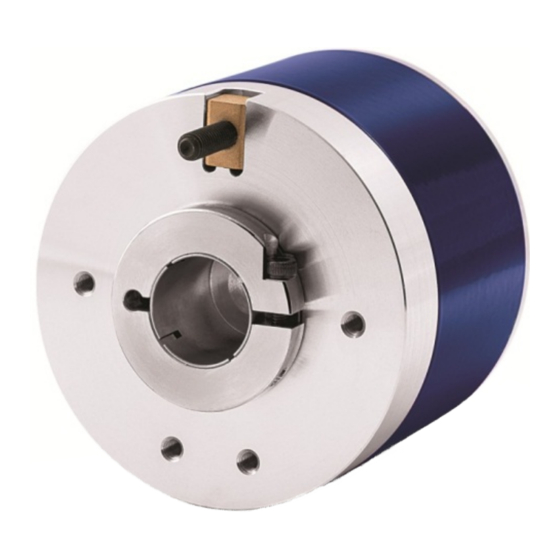
- Page 5 ENC58 programmable incremental encoder. ENC58 programmable encoder from Datalogic Automation is designed to maximize customization and versatility and really allows the operator to get, along with the position information, a complete parametrization and the better configuration that perfectly suit specific needs in a good many applications and machines.
-
Page 6: Safety Summary
Datalogic Automation S.r.l. assumes no liability for the customer's failure to comply with these requirements. Electrical safety Turn off power supply before connecting the device;... - Page 7 ENC58 PROG Mechanical safety Install the device following strictly the information in the section “3 – Mounting instructions”. mechanical installation has to be carried out with stationary mechanical parts; do not disassemble the encoder; do not tool the encoder or its shaft; ...
-
Page 8: Identification
Information is listed in the delivery document too. Please always quote the ordering code and the serial number when reaching Datalogic Automation s.r.l. for purchasing spare parts or needing assistance. For any information on the technical characteristics of the product... -
Page 9: Mounting Instructions
ENC58 PROG 3 - Mounting instructions WARNING Installation has to be carried out by qualified personnel only, with power supply disconnected and mechanical parts compulsorily in stop. 3.1 Solid shaft encoders Mount the flexible coupling 1 on the encoder shaft; ... -
Page 10: Installation Using A Flange (Code St-58-Flng)
ENC58 PROG 3.1.3 Installation using a flange (code ST-58-FLNG) -
Page 11: Hollow Shaft Encoders
ENC58 PROG 3.2 Hollow shaft encoders 3.2.1 AMT58-H15 Mount the encoder on the motor shaft using the reducing sleeve 8 (if supplied). Avoid forcing the encoder shaft; fasten the fixing plate 4 to the rear of the motor using two M3 cylindrical head screws 5;... -
Page 12: Electrical Connections
ENC58 PROG 4 - Electrical connections WARNING Electrical connection has to be carried out by qualified personnel only, with power supply disconnected and mechanical parts compulsorily in stop. Never force the rotation of the shaft manually, it could cause irreparable damage! WARNING If wires of unused signals come in contact, irreparable damage could be caused to the device. -
Page 13: M23 12-Pin Connector Specifications
ENC58 PROG 4.3 M23 12-pin connector specifications M23 12-pin connector Male Clockwise 4.4 M12 12-pin connector specifications Male Frontal side A coding 4.5 Connection of the shield For signals transmission always use shielded cables. The cable shielding must be connected properly to the metal ring nut 3 of the connector in order to ensure a good earthing through the frame of the device. -
Page 14: Ground Connection
ENC58 PROG 4.6 Ground connection Minimize noise by connecting the shield and/or the connector housing and/or the frame to ground. Make sure that ground is not affected by noise. The connection point to ground can be situated both on the device side and on user’s side. -
Page 15: Counting Direction Input
ENC58 PROG WARNING Please check the position of the 0 pulse and set it if necessary whenever you set a new resolution next to the Resolution parameter or reverse the counting direction. NOTE The width of the 0 pulse can be set next to the Z pulse width parameter. -
Page 16: Diagnostic Leds (Figure 1)
ENC58 PROG clockwise (and the decreasing count when the shaft is turning clockwise). When the option DOWN is set -Direction = DOWN-, if the Counting direction input has LOW logic level (0VDC) the encoder will provide the increasing count when the shaft is turning counter-clockwise (and the decreasing count when the shaft is turning clockwise);... -
Page 17: Index Pulse Setting External Button (Figure 1)
ENC58 PROG 4.11 Index pulse setting external button (Figure 1) This encoder provides the zero signal (Index pulse) once per revolution as relative positioning reference (home position, see the Figure on page 9). In this way a unique position can be identified at a well-known point in the 360°... -
Page 18: I2C (Inter Integrated Circuit) Serial Connection
To communicate with the encoder, you must connect the device to the personal computer through a USB port using the specific connection cable supplied by Datalogic Automation upon request. The connection cable code is KIT ENC58. It is provided with a M23 12-pin female connector for the devices having ZCZ output circuit code;... -
Page 19: Installing The Kit Enc58 Usb Drivers
The drivers package and the relevant documents are found inside the EXC_USB4_driver folder. As stated, the drivers are available for download at the following address www.datalogic.com. If you need to install the drivers under the Microsoft Windows XP operating system, please refer to the following document: Installation_Guide_for_WindowsXP.pdf. -
Page 20: Programming Interface
5.1 Configuring the encoder using the software tool ENC58 programmable incremental encoder is supplied with a software expressly developed and released by Datalogic Automation in order to easily programme and configure the device. It allows the operator to set the working parameters of the device and monitor whether the device is running properly. -
Page 21: Starting The Program
ENC58 PROG 5.2 Starting the program launch program just double-click ENC58_Rx_x_Datalogic_ENGLISH.exe executable file. Inside same folder find ENC58_Rx_x_Datalogic_ITALIANO.exe executable file to use the interface program with messages in Italian language, if needed. Press the OK button in the LICENSE page to go on. In this way you also agree with the terms and conditions of use of the software. - Page 22 ENC58 PROG The main page of the configuration interface will appear. It consists of a single page where all parameters and the complete diagnostic information concerning the connected encoder are available. Three sections can be found in the page: 1. a top left section where the parameters to program the encoder can be found;...
-
Page 23: Connection With The Encoder
ENC58 PROG 5.3 Connection with the encoder If the PC and the encoder have been connected properly using the KIT ENC58 connection cable, as soon as you press the DISCONNECTED button the parameters in the interface are initialized to the values which are stored on the encoder memory. A proper connection is shown by the button turning green and changing its label into CONNECTED. - Page 24 ENC58 PROG If the encoder is not connected properly and the software tool is not able to establish a USB connection, then the USB to I2C not found: check connections!!! warning message appears on the screen. In such occurrence please check that the USB cable is connected properly to the USB port and the USB port is working correctly.
-
Page 25: Setting The Parameters
ENC58 PROG 5.4 Setting the parameters WARNING Please always be aware that the parameters set in the interface are not permanent, they are only stored temporarily in the RAM of the encoder. For instance, should you disconnect the USB cable and so cut off the power supply, data which has been set previously would be lost! To save the data on the EEPROM permanently, after having entered... - Page 26 ENC58 PROG NOTE Please note that the maximum counting frequency of an encoder, expressed in kHz, results from the number of revolutions per minute (RPM) -i.e. its rotational speed- and the number of pulses per revolution (PPR) -i.e. its resolution. It can be calculated by using the following algorithm: RPM * PPR Maximum counting frequency (kHz) =...
- Page 27 ENC58 PROG Example 1 Let's assume that the encoder is mounted on the driven draw roller of a slitter and the circumference of the roller is 753 mm. We can set a resolution of 7530 PPR (Resolution = 7530) to control the movement of the roller with a tenth of a millimetre resolution.
- Page 28 ENC58 PROG We can set a resolution of 55000 PPR (Resolution = 55000) to control the movement of the cable and thus of the axis with a tenth of a millimetre resolution. In this way we convert a rotary measurement value (55000 PPR) into a linear measurement value, therefore we are able to control the 5.5- m long linear travel with a tenth of a millimetre resolution.
- Page 29 ENC58 PROG at which the 0 pulse is located in the 360° revolution of the encoder shaft is displayed. Default = 0 (min. value = 0; max. value = 262143) WARNING Please check the position of the 0 pulse and set it if necessary whenever you set a new resolution next to the parameter Resolution...
- Page 30 ENC58 PROG Z pulse width This parameter allows to set the width of the Index pulse (0 pulse) expressed in electrical degrees. Two options are available and selectable in the drop-down box: 90° and 180°. Please note that the 0 pulse having a width of 90 electrical degrees is synchronised with A and B pulses, while the 0 pulse having a width of 180 electrical degrees is synchronised with A pulse.
- Page 31 ENC58 PROG Direction By default the phase relationship between A and B channels is so that the rising edge of A channel leads the rising edge of B channel when the encoder is rotating in a clockwise direction (see the Figure above in the page).
-
Page 32: Loading The Encoder Configuration From A File
ENC58 PROG For any information on the electrical connection of the Counting direction input refer to the sections “4- Electrical connection“ on page 7 and “4.9 Counting direction input“ on page 10. WARNING After having set the new counting direction it is necessary to set also the Index pulse. -
Page 33: Saving The Parameters On Eeprom
ENC58 PROG 5.4.3 Saving the parameters on EEPROM Write EEPROM The parameters set in the interface and sent to the encoder are not permanent as they are only stored temporarily in the RAM of the encoder. For instance, should you disconnect the USB cable and so cut off the power supply, data that has been set previously would be lost! To save the data on the EEPROM permanently, after having entered... -
Page 34: Error Messages
ENC58 PROG 5.5 Error messages (in alphabetical order) Activation error of sensor data!!!!! The operator has pressed the READ button but an error has occurred while processing the information (it is signalled through the LED lit red in the diagnostic information section of the page). Please close the programming interface, then turn off and on the power supply of the encoder (disconnect and connect again the USB cable), finally restart the programming interface. - Page 35 ENC58 PROG Error Flags in Register 'Status Register'!! An error is active in the “Status” register. It is signalled through the LED lit red in the diagnostic information section of the page. Error Flags in Register 'µC Error'!! An error is active in the “µC Error” register. It is signalled through the LED lit red in the diagnostic information section of the page.
- Page 36 ENC58 PROG has HIGH logic level (+VDC) the encoder will provide the increasing count when the shaft is turning clockwise (and the decreasing count when the shaft is turning counter-clockwise). USB to I2C not found: check connections!!! This warning message is triggered if the encoder is not connected properly and the software tool is not able to establish a USB connection.
-
Page 37: Default Parameters List
ENC58 PROG 6 - Default parameters list Parameters list Default value 1024 Resolution Preset 90° Z pulse width Voltage output Direction... - Page 38 www.datalogic.com...
Need help?
Do you have a question about the ENC-58 PROG and is the answer not in the manual?
Questions and answers