Table of Contents
Advertisement
Quick Links
Advertisement
Table of Contents

Related Manuals for Datalogic DB0431


Summary of Contents for Datalogic DB0431
- Page 1 DB0431 OEM Decoder Integration Guide...
- Page 2 Datalogic S.p.A. and/or its affiliates. Owners of Datalogic products are hereby granted a non-exclusive, revocable license to reproduce and transmit this documentation for the purchaser' s own inter- nal business purposes.
-
Page 3: Table Of Contents
About this Manual ......................................1 Manual Conventions ..................................1 Outline ........................................2 Technical Support ......................................2 Support Through the Website ................................2 Reseller Technical Support ..................................2 About the DB0431 ....................................2 Unpacking the Decoder ...................................2 OEM Decoder Care ....................................3 System Overview .....................................3 Regulatory .......................................3 INSTALLATION ....................................4 Mounting the OEM Decoder ....................................4... - Page 4 Contents NOTES DB0431 OEM DECODER...
-
Page 5: Introduction
DB0431 decoder (desig- nated as "OEM decoder" in this manual) specifically into equipment-inte- grated scanning applications. DB0431 includes two interfaces on the same model (on the host connector as will be described in the chapter 3: electrical integration): •... -
Page 6: Outline
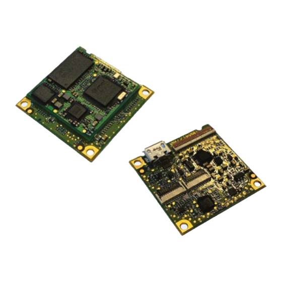
About the DB0431 The Datalogic DB0431 decoder is a compact, high performance decoder to be connected to a MIPI CSI-2 or PARALLEL Datalogic scan engine in order to enable the decoding of linear and 2D barcodes and to transmit the decoded information to a host by means of a TTL, UART or USB COM or HID Keyboard interface. -
Page 7: Oem Decoder Care
OEM decoder. System Overview The Datalogic DB0431 OEM decoder features a digital platform based on a Microchip ARM A5 processor, able to capture and decode images from either a MIPI or PARALLEL video interface. The video interfaces are compatible with any Datalogic 2D undecoded scan engine. -
Page 8: Installation
Always make sure that OEM Decoder is powered off before connecting Scan Engine to the 21 poles connector. Only connect one Scan Engine at a time. Connect only Datalogic 2D MIPI Scan Engines to the MIPI 21-poles connector and connect only Datalogic 2D parallel Scan Engines to the parallel 21-poles connector. -
Page 9: Mechanical Size
Mounting the OEM Decoder Mechanical Size Nominal size: 30 mm (width) x 6.45 mm (height) x 30 mm (depth) Maximum size: 30.1 mm(width) x 6.55 mm (height) x 30.1 mm (depth) Figure 3 - Decoder Size Integration Guide... -
Page 10: Mounting Holes
Installation Figure 4 - Connector Position Mounting Holes There are three mounting holes and a notch to center and secure the OEM decoder to a host mounting system. Figure 5 - Mounting Holes and Related Requirements DB0431 OEM DECODER... -
Page 11: Electrical Integration
Chapter 3 Electrical Integration Supply Voltages and I/O levels Table 3 - Supply Voltages and I/O Levels Item Level Description This is the core digital and analog power sup- ply. The device full operation is guaranteed in this range of voltage (compatible with USB powering). -
Page 12: Integration Notes
ALWAYS ON mode continuously for an extended time. In some cases, the DB0431 might detect an overheat condition of the con- nected scan engine and might apply power reduction strategies (like reduc- ing FPS or turning off AIM laser). - Page 13 Electrical Interface • decoded information transmitted by means of USB COM or HID Key- board interface (referred to as decoded USB) Signals on connector are mapped as follows: Table 4 below describes the power lines and the signals mapped on the 27- pole ZIF connector: 1.
- Page 14 If this power is not supplied, the PWR_ON_CTRL signal behaves only as an output (see pin 16). 18.VCC_ILLUM: additional pin for Illumination power supply 3.0 - 5.5 V. DB0431 OEM DECODER...
-
Page 15: Power Supply And I/O Voltage
Electrical Interface 19.GND: main power supply ground. 20.STAND_MODE: Input, stand mode control signal, active high. When high, activates the stand mode operation that is automatically trig- gering the decoder by analyzing the changes on the images coming from the 2D camera video stream. 21.GND: main power supply ground. - Page 16 UART interface in ≃351ms (width ≃3ms) bootloader and application. T ready: system is ready, OEM decoder is in IDLE mode, POWER_ON_CTRL is <1100 ms stable high With Vcc at 3.3V add about 33ms to all time values. DB0431 OEM DECODER...
-
Page 17: Scan Engine Parallel Or Mipi Connection
Electrical Interface Scan Engine PARALLEL or MIPI Connection Table 6 - Electrical Interface of the MIPI Video Connector. Signal I/O type Description power Ground I2C_DATA I2C Data I2C_CLK I2C Clock VCC_ILLUM_SYS power Illumination system power supply VCC_ILLUM_SYS power Illumination system power supply power Digital and sensor power supply Reserved... -
Page 18: Connector And Flat Cable (Host Interface)
For a detailed description of the signals above please refer to the scan engine integration manual. Connector and Flat Cable (Host Interface) The DB0431 decoder is equipped with a 27-pole ZIF connector. The host connector is 27-pole ZIF connector 0.5 mm pitch made for 0.2 mm thick flat cables. -
Page 19: Usb Powered Host And Usb Interface Design Recommendations
OEM Decoder Operation USB Powered Host and USB Interface Design Recommendations The OEM decoder features some basic ESD protection and a controlled soft start during power up sequence, with a peak surge current below 130 mA (about 400us width) during input voltage ramp-up. Additional peaks are present during boot phase (see figure 11 for boot time), with a maximum peak below 250 mA (about 800us width). - Page 20 In this use case, the LOW POWER commands should not be sent to OEM decoder and AIM_CTRL line should be always kept low and UART_RX kept high while in USB suspend (and before any LOW POWER transition). DB0431 OEM DECODER...
- Page 21 After a period of "ON" time the decoder is switching off the scan engine illumination stepping back to sensing the field of view for an object to come in. See DB0431 USER GUIDE for more details. Mode transition sequences and mode corresponding inputs are described in...
-
Page 22: Communication
(Default) If USB Composite interface is used, the OEM decoder sends decod- ing result as a normal keyboard output, and it also opens a USB COM port for configuration or communication with the host using DESP protocol. DB0431 OEM DECODER... -
Page 23: Technical Specifications
Appendix 4 Technical Specifications This section lists the technical specification of the DB0431 OEM decoder. Refer to the appropriate Datalogic Scan Engine integration guide for informations related to scan engine performances. Item Description Physical Characteristics Nominal size: Width 30 mm Height 6.45 mm... - Page 24 ESD Level ±2.0kV @ connector Regulatory Illumination System IEC 62471 Exempt risk group (GREEN LED) Environmental RoHS compliant Table 11 - List of Datalogic Compatible Scan Engines Scan Engine Resolution AIMING Types DE2011-DL 752x480 40°H x 26°V Laser cross + dots...
-
Page 25: Shielded Double Side Flex 21 Example Drawing
Technical Specifications Shielded Double Side FLEX 21 Example Drawing Integration Guide... -
Page 26: Ordering Information
Ordering Information OEM Decoder is available in a single model providing all possible output interfaces (DB0431). The default interface is USB composite, refer to the User's Guide for instructions about different interface configurations. In order to test decoder and scan engine performance, 2 demo kits are avail- able: •... - Page 28 ©2020 Datalogic S.p.A. and/or its affiliates. All rights reserved. Datalogic and the Datalogic logo are registered trademarks of Datalogic S.p.A. in many countries, including the U.S. and the E.U. Datalogic S.r.l. Via S. Vitalino, 13 Calderara di Reno 40012...
Need help?
Do you have a question about the DB0431 and is the answer not in the manual?
Questions and answers