Table of Contents
Advertisement
Quick Links
Advertisement
Table of Contents

Subscribe to Our Youtube Channel
Related Manuals for Pitney Bowes F65A


Summary of Contents for Pitney Bowes F65A
- Page 1 Feeder/Loader F65A/B Operator Guide English Version...
- Page 3 Introduction This manual contains instructions on the operation and maintenance of this machine. To get the maximum versatility from this machine all operators should carefully read and fol- low the instructions in this manual. Keep this manual in a handy place near the machine. Please read the Safety Information before using this machine.
- Page 4 Follow the normal safety precautions for all office equipment: • Use only Pitney Bowes approved supplies, in particular aerosol dusters. Improper stor- age and use of aerosol dusters or flammable aerosol dusters can cause an explosive- like condition that could result in personal injury and/or property damage. Never use aerosol dusters labeled flammable and always read instructions and safety precautions on the duster label.
- Page 5 • Before clearing a stoppage, be sure machine mechanisms come to a stop. • When removing stalled material, avoid using too much force to protect against minor personal injury and damaging equipment. • To prevent overheating, do not cover any vent openings. •...
-
Page 7: Table Of Contents
TABLE OF CONTENTS What You Can Do With This Machine .................... 9 Guide To Components ........................11 F65A/B Feeder/Loader ....................... 11 High Capacity Loader ......................... 12 User Interface ..........................12 1. Operation Operation ............................13 F65A/B setup ..........................13 Power Up ..............................13 Program selection ..........................14... - Page 8 Double feed ............................38 Low performance ..........................38 5. General Remarks Do’s And Don’ts ..........................39 6. Specifications Machine Specifications ......................... 41 F65A/B Feeder incl. High capacity loader .................. 41 OMR............................42 Application functionality ........................42 Physical specification .........................42 OMR reading area..........................43 Top reading ............................43 Bottom reading ..........................44...
-
Page 9: What You Can Do With This Machine
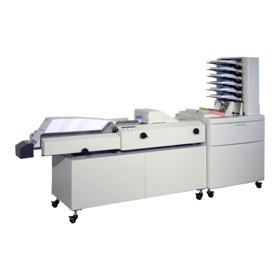
The System Overview shows the Loader, Feeder and User Interface as it is designed for the DI880 System. The F65A/B is capable of loading about 200 sheets of 80g paper. The High Capacity Loader expands the capacity with up to 4000 sheets. They are easy to handle and allow the User to load paper at any time without interruption of the production flow. -
Page 11: Guide To Components
Guide To Components F65A/B Feeder/Loader Separation Feeder Head Accumulator Side Adjustment Locking Guides User Interface Ramp Material Dump Exit Sensor Sensor Feeder Belt O-ring Motor Side Guides Ramp Dump Motor Adjustment Material Height Eject Motor Accumulator Side Sensor Guide Adjustment... -
Page 12: High Capacity Loader
High Capacity Loader Transport Belt Side Guides Ramp Belt Ramp Motor Transport Motor Side Guides Adjustment There are only two adjustments necessary: the side guides for size and the distance be- tween ramp and the feeder. User Interface Display 2 x 20 Character Select (scroll) Start Exit Job... -
Page 13: Operation
1. Operation Operation To run the F65A/B correctly, some adjustments are necessary. There is the mechanical setup, the scanner setup and the job (i.e. program) selection. F65A/B setup The most efficient method is to go through the pre-run adjustments. If you are starting a different job than was running before, you will be guided through these adjustments. -
Page 14: Program Selection
Program selection To select a program, scroll until it appears on the first line of the display as indicated by the arrow <PROG prompt. Press GREEN to select the program. 029> OMREX Paper/ DF OMR <PROG 030> EXAMPLEJOB Paper/ DF BCR You are asked about running pre-run adjustments. -
Page 15: Feeder Side Guides Adjustment
Feeder side guides adjustment The display shows the second instruction: 2. Feeder side guide adjustment GREEN=CONFIRM BLUE=EXIT Rotate the feeder Side Guide adjustment wheel anticlockwise until the side guides give ap- proximately 3mm of clearance between the material and the side guides. Press GREEN to go to the next step. -
Page 16: Set The Scanning Head
Set the scanning head The OMR scanner has to be in the middle of the OMR Code flow. Make sure that the scan- ner is as close as possible to the paper (reading quality is much better). 3. Adjust the OMR Scanner GREEN=CONFIRM BLUE=EXIT OMR Light indicates effective reading position... -
Page 17: Side To Side Adjustment Of Bcr Scanners
Side to side adjustment of BCR scanners The BCR scanner is positioned in front of the separation head and can be positioned with- out any tools. Be aware that the scanner needs a minimum distance to the code. Setting material guide fingers If the paper is curled, you can use the material guide fingers. -
Page 18: Feeder Head Adjustment
Feeder head adjustment Ensure that the feeder separation head is at its base position. The black and red lever (A) has to be in a horizontal position and stepped in with a click. The following message is shown on the display: 3. -
Page 19: Transport Material To Accumulator
Transport material to accumulator Turn the Accumulator Side Guide adjustment wheel anticlockwise to open the accumulator side guides as wide as needed. Load one piece of material and press Run /confirm (green) until it is fed into the accumulator. The display shows the message: 4. -
Page 20: Accumulator Ramp Adjustment
If you need to use the outermost position of the Accumulator Side Guides, you have to lift the o-rings to clear the side guides while adjusting. Accumulator ramp adjustment The ramp adjustment is achieved in the same step. The yellow mark should be visible if a piece of material is in the accumulator. Start the Job If you finished the pre run adjustments (or skipped them) you will have a short overview of your job on the display:... -
Page 21: High Capacity Loader Setup
High capacity loader setup Transport material to feeder Adjust the loader transport belt assembly lengthwise to the feeder by sliding it into the cor- rect position. Recommended adjustment is when the sheet, held in the feed direction, fits between the slope on the transport belt assembly and the separation housing as illustrated. -
Page 22: Setting The Loader Side Guides
Setting the loader side guides Adjust the loader side guides by turning the adjustment wheel until the side guides give approximately 3mm of clearance between the material and the side guides. -
Page 23: Main Menu
2. Main menu Job Handling To reach the main menu, press GREEN, BLUE and RED simultaneously, this procedure avoids an unintended change of settings of the machine and as well of the stored jobs. The main menu contains five submenus four concerning jobs and one (Service Menu) for parameter setting, fault detection and maintenance. -
Page 24: Choice Of Material
Choice of material The choice of Material is important to the appliance of the Double Feed detection, there are three different settings available: • Paper NO Double Feed detection • Paper /DF Standard Double Feed detection • Paper /DF+ Advanced Double Feed detection DF+ setting is used if there is larger, dark printed areas in the line of the Double Feed detector, which can cause false detection. -
Page 25: New Scanning Job
New scanning job • There are three type of scanning available. • • • 2D Matrix The BCR and 2D Matrix code are very similar in their basic structure. They vary only in the available size of data. BCR code contains technically less information than 2D Matrix Code. -
Page 26: Omr Location (Scanner Postion)
OMR location (scanner postion) Here you select the scanner position, all available positions are defined in the Service menu, here you can only select already defined positions. 001> OMR Location: TOP-REAR <>=SELECT Green=CONF. Blue=EXIT Red=GO ON Scan line increment To do this measure the minimum distance between the scan lines which are right next to each other: •... -
Page 27: Bypass Advanced Settings
Bypass advanced settings The system asks if Advanced Settings should be bypassed. Pressing RED will display the advanced settings. Proceed through the following four parameters by pressing GREEN to continue and the Arrow Buttons to edit the selection. Set Integrity/WAS/SSQ: -LSB (least significant bit) -MSB (most significant bit) Set Integrity random:... - Page 28 The system has jumped to scan line position 6. Scroll to the scan function DVF and press GREEN to confirm. : [ 6] <-->=SELECT Green=CONF. Blue=END Red=IGNORE Set the 7th scan line position in the same manner as position 3(,4,5). Set SI2 for two scan line positions occupied by the system integrity scan function (SI).
-
Page 29: Bcr Job Example
BCR job example The BCR data structure is not flexible but the functionality is selectable. Program name This section covers programming a job where scanning is required. When you program the Feeder for a particular scanning job, assign the job a name (the number is automatically given by the next free job number) 001>... -
Page 30: Set Integrity
Set integrity The maximum is defined as four characters. You can set a number between 0 and 4 for this definition. 001> SI (0-4): 2 <>=SELECT Green=CONF. Blue=EXIT Red=GO ON We select “2” in our example. Select feed Depending on your job there is a possibility to add selective material from the MF 4000. 001>... -
Page 31: Bcr Location (Scanner Position)
BCR location (scanner position) Here you select the scanner position, all available positions are defined in the Service menu here you can only select already defined positions. 001> BCR Location: TOP-REAR <>=SELECT Green=CONF. Blue=EXIT Red=GO ON We select “TOP-REAR” in our example. Job id The maximum is defined as 31 characters. -
Page 32: Modify Job
Modify job The actual selected job will automatically be selected in the modify job menu. You can scroll through the programmed jobs until the job to be modified has been found by using the two arrow buttons for selection. Jobs may be identified by their number or name (far left/far right on top line, see diagram below). -
Page 33: Settings
IGNore (IGN) This function is to tell F65A/B to ignore certain marks. This if the OMR code used has got marks not supported by the system or that certain marks should be ignored. -
Page 34: Always 0 (Alw0)
ALWays 0 (ALW0) This is an integrity check. If always 0 (zero) is defined in the OMR profile, the reader ex- pects a 0 (zero) in this position on every sheet. Anything else will be regarded as an integ- rity error. ALWays 1 (ALW1) This is an integrity check. -
Page 35: Machine Control Functions
Note The EOC must be present. Without the EOC mark, the F65A/B will not work. Selective Feed 1 to 7 (SF1 to 7) When this mark is detected, one or more selected enclosures will be added to the actual set. -
Page 36: Divert Finished (Dvf)
DiVert Finished (DVF) When this mark is detected, the actual set will be processed without having the envelope sealed. The next set will have the envelope sealed unless a new DVF mark is detected. Note The DVF mark must be present on the first sheet of the new set. DiVert to Deck (DVD) When this mark is detected, the actual set will be transported to the outsort bin on the folder. -
Page 37: Trouble Shooting
4. Trouble shooting Clearing paper jam The Feeder may stop indicating a misfeed. The indicator STOP/CLEAR DECK will be flashing. Follow the procedure given next: • Feeder Head section • Open the Top Cover [A] • Remove the sheets from Feeder Deck [B] •... -
Page 38: Paper Feeding
The causes for jam are mostly related to: • Dusted separation header area • Electrostatic affected paper (paper separation difficult) • Too much humidity (paper separation difficult) • Too much paper on the feeder belt • Separation header too close •... -
Page 39: General Remarks
5. General Remarks Do’s And Don’ts • Always follow all warnings marked on, or supplied with, the equipment. • Always exercise care when moving the equipment. Always contact service if relocating the equipment. CAUTION: Unplug the power cord from the wall outlet and machine before you move or relocate the equipment. -
Page 41: Specifications
6. Specifications Machine Specifications F65A/B Feeder incl. High capacity loader Speed: Up to 15000 sheets/hour Min: 147 x 210 mm (5.8” x 8.2”) Paper size (H x W)* Max: 297 x 297 mm (11.7” x 11.7”) Min: 60 gsm Paper weight... -
Page 42: Omr
Application functionality Benchmark (Start mark) • Ignore • Parity even • Parity Odd • Wrap a round counter (Static 1-N or N-1) • Sequence counter (Dynamic for each set) • Start of collation • End of collation • • Always 0 •... -
Page 43: Omr Reading Area
OMR reading area Top reading Lead 45 mm edge (1.77”) 55 mm 105 mm 30 mm (2.16”) (4.13”) (1.18”) 40 mm 65 mm (1.57”) (2.56”) 10 mm 10 mm (0.39”) (0.39”) No OMR marks 30 mm in shaded areas (1.18”) -
Page 44: Bottom Reading
OMR reading area, continues Bottom reading Lead 45 mm edge (1.77”) 30 mm 130 mm 30 mm (1.18”) (5.17”) (1.18”) 65 mm 65 mm (2.56”) (2.56”) 10 mm 10 mm (0.39”) (0.39”) No OMR marks 30 mm in shaded areas (1.18”) -
Page 45: Custom Top And Bottom With A Camera Like Scanner
OMR reading area, continues Custom top and bottom with a camera like scanner 15 mm (0.79”) Lead edge 10 mm 10 mm (0.39”) (0.39”) 65 mm (2.56”) No OMR marks in shaded areas... -
Page 46: Barcode
Barcode Application functionality Machine can run Barcode standards:I25, Code 128, Code 39, Set page counter and Set Total Number • Selective feed 1 – 10 • Customer specific functionality can be implemented at request. • 2D application functionality Machine can run 2D code standards: DataMatrix ECC 200. Job ID •... -
Page 47: Barcode Reading Area
Barcode reading area Top and bottom loading Lead 10 mm edge 10 mm (0.39”) (0.39”) 10 mm (0.39”) 10 mm 10 mm (0.39”) (0.39”) 10 mm (0.39”) No OMR marks in shaded areas... - Page 48 Notes...
- Page 50 Stamford, Connecticut 06926 www.pitneybowes.com PB Form SDC991B (9-22) © Pitney Bowes Limited, 2022 We have made every reasonable effort to assure the accuracy and usefulness of this guide, however we cannot assume responsibility for errors or omissions or liability for the misuse or misapplication of our products.
Need help?
Do you have a question about the F65A and is the answer not in the manual?
Questions and answers