Table of Contents
Advertisement
Quick Links
Advertisement
Table of Contents

Subscribe to Our Youtube Channel
Related Manuals for Kramer TWA


Summary of Contents for Kramer TWA
- Page 1 Kramer Electronics, Ltd. USER MANUAL Model: Cobra TWA...
-
Page 2: Table Of Contents
Installing the Cobra TWA Powering the Cobra TWA Solutions to Common Problems Technical Specifications Figures Figure 1: Connecting the Cobra TWA Transmitter Tables Table 1: HD15 Video Connector PINOUT Table 2: T568B CAT5 PINOUT Table 3: Technical Specifications of the Cobra TWA Contents... -
Page 3: Introduction
GROUP 6: Accessories and Rack Adapters; GROUP 7: Scan Converters and Scalers; and GROUP 8: Cables and Connectors 2 Download up-to-date Kramer user manuals from the Internet at this URL: http://www.kramerelectronics.com 3 The complete list of Kramer cables is on our Web site at http://www.kramerelectronics.com Introduction , which are clearly defined series products. - Page 4 (often associated with low quality cables) Avoiding interference from neighboring electrical appliances that may adversely influence signal quality and positioning your Cobra TWA in a location free from moisture and away from excessive sunlight and dust Caution...
-
Page 5: Setup And Installation
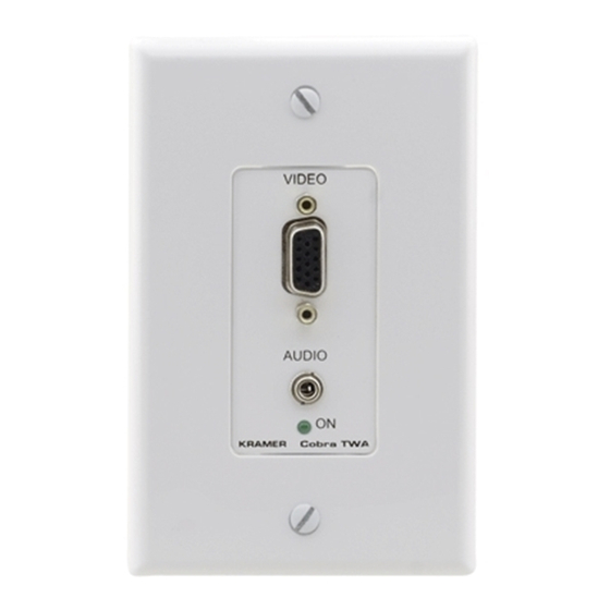
Setup and Installation The section describes how to setup and install the Cobra TWA. In general, the connection and setup procedure at both transmitter and receiver ends is as follows: At the transmitter end: 1. Connect the source video to the Cobra Series transmitter video input port, which is an HD15 connector labeled VIDEO. -
Page 6: Connections On The Cobra Twa
Figure 1: Connecting the Cobra TWA Transmitter 4.2 Installing the Cobra TWA The Cobra TWA transmitter can be installed into a 1 gang electrical wall box and fits a standard Decora wall plate cover. The installation must conform to national and local electrical codes. -
Page 7: Solutions To Common Problems
For five-component (RGB/H&V) AC coupled video, the Cobra Transmitter unit has been designed with full DC restoration capability. The Cobra TWA may need to be replaced with a Universal transmitter Solutions to Common Problems... -
Page 8: Table 1: Hd15 Video Connector Pinout
Solutions to Common Problems RGBS RGsB Composite SVHS Red + Red + Green+ Green+ Blue+ Blue+ — — Red- Red- Green- Green- Blue- Blue- — — — — — — C Sync — — — — KRAMER: SIMPLE CREATIVE TECHNOLOGY (Y/C) -
Page 9: Table 2: T568B Cat5 Pinout
Solutions to Common Problems Table 2: T568B CAT5 PINOUT... -
Page 10: Technical Specifications
SIZE: WEIGHT: 1 Specifications are subject to change without notice Technical Specifications of the Cobra TWA Category 5, 5e, 6 shielded or unshielded twisted pair CE; FCC Class A, IC Class/class A RGBHV, RGB, Composite, S-Video, Component Video modes 1920x1200 @ 60Hz (receiver dependent) Audio OUT: 600 ohms maximum Video IN: 75 ohms;... - Page 12 For the latest information on our products and a list of Kramer distributors, visit our Web site: www.kramerelectronics.com, where updates to this user manual may be found. We welcome your questions, comments and feedback. Safety Warning: Disconnect the unit from the power supply before opening/servicing.
Need help?
Do you have a question about the TWA and is the answer not in the manual?
Questions and answers