
Subscribe to Our Youtube Channel
Related Manuals for Kramer TP-410


Summary of Contents for Kramer TP-410
- Page 1 K R A ME R E LE CT R O N IC S L T D . USER MANUAL MODEL: TP-410 UXGA-Audio-RS-232 Line Transmitter / DA P/N: 2900-000733 Rev 3...
-
Page 3: Table Of Contents
Default EDID Kramer Communication Protocol 2000 Figures F igure 1: TP-410 UXGA-Audio-RS-232 Line Transmitter / DA Front Panel F igure 2: TP-410 UXGA-Audio-RS-232 Line Transmitter / DA Rear Panel F igure 3: Connecting the TP-410, UXGA-Audio-RS-232 Line Transmitter / DA... -
Page 4: Introduction
Introduction Welcome to Kramer Electronics! Since 1981, Kramer Electronics has been providing a world of unique, creative, and affordable solutions to the vast range of problems that confront video, audio, presentation, and broadcasting professionals on a daily basis. In recent years, we have redesigned and upgraded most of our... -
Page 5: Getting Started
Do not secure the cables in tight bundles or roll the slack into tight coils • Avoid interference from neighboring electrical appliances that may adversely influence signal quality • Position your Kramer TP-410 away from moisture, excessive sunlight and dust TP-410 - Getting Started... -
Page 6: Overview
10-channel VGA/UXGA, audio and data to CAT 5 transmitter for high resolution video, unbalanced stereo audio (or S/PDIF digital audio) and full-duplex RS-232 signals. The CAT 5 input can also be connected to any Kramer compatible TP transmitter (for example, the TP-125EDID) and the CAT 5 outputs can be connected to any Kramer compatible TP receiver (for example, the TP-126). -
Page 7: Shielded Twisted Pair (Stp) / Unshielded Twisted Pair (Utp)
(that is connected to the display’s source). The EDID enables the TP-410 to “know” what kind of monitor is connected to the output. The EDID includes the manufacturer’s name, the product type, the timing data supported by the display, the display size, luminance data and (for digital displays only) the pixel mapping data. -
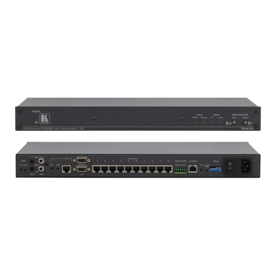
Page 8: F Igure 1: Tp-410 Uxga-Audio-Rs-232 Line Transmitter / Da Front Panel
Figure 1: TP-410 UXGA-Audio-RS-232 Line Transmitter / DA Front Panel Feature Function POWER LED Lights when the unit receives power AUDIO LEDs S/PDIF Lights when a local digital audio input is selected ANALOG Lights when a local analog audio input is selected... -
Page 9: F Igure 2: Tp-410 Uxga-Audio-Rs-232 Line Transmitter / Da Rear Panel
Figure 2: TP-410 UXGA-Audio-RS-232 Line Transmitter / DA Rear Panel Feature Function EDID STATUS LED Lights during normal operation; blinks when acquiring the EDID CAPTURE Button Press to acquire the EDID information from the display (see Section 9 AUDIO ANALOG 3.5mm Mini... - Page 10 Feature Function RS-485 (G,B,A) Connect to the RS-485 controller. Pins B (-) and A (+) are for RS-485; connect pin G to the cable shield (if required) ETHERNET Connector Connects to the PC or other Serial Controller through computer networking FLASH N/A (for factory use only) FACTORY RESET...
-
Page 11: Installing In A Rack
Installing in a Rack This section provides instructions for rack mounting the unit. TP-410 - Installing in a Rack... -
Page 12: Connecting The Tp-410
Connecting the TP-410 Always switch off the power to each device before connecting it to your TP-410. After connecting your TP-410, connect its power and then switch on the power to each device. To connect the TP-410, as illustrated in the example in Figure 1. -
Page 13: F Igure 3: Connecting The Tp-410, Uxga-Audio-Rs-232 Line Transmitter / Da
Figure We recommend that you use only the power cord that is supplied with this machine Figure 3: Connecting the TP-410, UXGA-Audio-RS-232 Line Transmitter / DA When using the TP as the source, adjust the EQ/LEVEL trimmers immediately after turning the power ON. It is recommended to perform this adjustment using the OUT local display. -
Page 14: Connecting To The Tp-410 Via An Rs-232 Connection
1. Connect the RS-232 Tx pin on the TP-410 to pin 2 (9-pin D-sub) on the RS-232 device. 2. Connect the RS-232 Rx pin on the TP-410 to pin 3 (9-pin D-sub) on the RS-232 device. 3. Connect the RS-232 G pin on the TP-410 to pin 5 (9-pin D-sub) on the RS-232 device. -
Page 15: Connecting To The Tp-410 Via The Ethernet
5.4.1 Connecting the ETHERNET Port directly to a PC (Crossover Cable) You can connect the Ethernet port of the TP-410 to the Ethernet port on your PC, via a crossover cable with RJ-45 connectors. This type of connection is recommended for identification of the factory default IP Address of the TP-410 during the initial configuration. -
Page 16: F Igure 5: Local Area Connection Properties Window
5.4.2 Connecting the ETHERNET Port via a Network Hub (Straight-Through Cable) You can connect the Ethernet port of the TP-410 to the Ethernet port on a network hub or network router, via a straight-through cable with RJ-45 connectors. 5.4.3 Ethernet Port Configuration To configure the Ethernet parameters, set DIP-switches 1 to 4 to ON (ON-ON-ON- ON), turn the power off and then back on. -
Page 17: Connecting Several Tp-410 Units
The latest version of K-UPLOAD and installation instructions can be downloaded from the Kramer Web site at www.kramerelectronics.com Connecting Several TP-410 Units You can daisy chain up to 15 TP-410 machines, as illustrated in Figure Figure 7: Connecting Multiple TP-410 Units TP-410 - Connecting the TP-410... -
Page 18: Configuration And Distribution Of Control Data
In this example, a local computer graphics source is connected to the UXGA IN 15-pin HD connector and the S/PDIF audio input of the TP-410 unit that is in the local mode. Outputs 2 and 5 are connected to TP-126 units and output 10 is... -
Page 19: F Igure 8: Local Control Via Rs-232
Ethernet. The machines in this configuration are identified by their address number and output location, as illustrated in Figure Figure 9: Control via the Ethernet TP-410 - Configuration and Distribution of Control Data... -
Page 20: F Igure 10: Rs-232 Remote Control
6.1.4 Connecting Multiple TP-410 Units via the RS-485 Bus You can connect up to 15 TP-410 units via the RS-485 bus with control from a PC or serial controller. To connect up to 15 TP-410 units via RS-485 (see Figure 11): 1. -
Page 21: F Igure 11: Connecting Multiple Tp-410 Units Via Rs-485
Figure 11: Connecting Multiple TP-410 Units via RS-485 TP-410 - Configuration and Distribution of Control Data... -
Page 22: The Setup Dip-Switches
The SETUP DIP-switches The DIP-switches on the TP-410 set the machine number of the unit. Moving a DIP-switch down turns the switch on, moving it up turns the switch off. Changing any DIP-switch requires that you turn the TP-410 power off and then on again. -
Page 23: Setting The Rs-232/Rs-485 Baud Rate Dip-Switches
To configure the Ethernet parameters, set DIP-switches 1 to 4 to ON (ON-ON-ON- ON), turn the power off and then turn the power on again. Use the Kramer K-UPLOAD software to configure the Ethernet. The latest version of K-UPLOAD and installation instructions can be downloaded from the Kramer Web site at www.kramerelectronics.com... -
Page 24: Setting The Rs-485 Bus Termination
The DIP-switch sets the RS-485 bus termination. Only the first and last physical devices on the RS-485 bus must be terminated (set to ON), all other devices must be set to OFF. Figure 14: TP-410 DIP-switch RS-485 Termination TP-410 - The SETUP DIP-switches... -
Page 25: Wiring The Cat 5 Line In / Line Out Rj-45 Connectors
Blue / White Green Brown / White Brown Pair 1 4 and 5 Pair 2 1 and 2 Pair 3 3 and 6 Pair 4 7 and 8 TP-410 - Wiring the CAT 5 LINE IN / LINE OUT RJ-45 Connectors... -
Page 26: Acquiring The Edid
Acquiring the EDID The TP-410 can acquire the EDID information from a display connected to the UXGA IN 15-pin HD connector on the TP-410, or acquire the default EDID. To acquire the display EDID, do the following: 1. Connect the UXGA IN 15-pin HD connector to the input XGA connector of the display, using a short cable. -
Page 27: Flash Memory Upgrade
Flash Memory Upgrade You can upgrade the TP-410 via the Kramer K-UPLOAD software. Before running K-UPLOAD, set DIP-switches 1 to 4 to ON (ON-ON-ON-ON), turn the power Off and then back On. After completion of flash memory upgrade, set DIP-switches 1 to 4 to their previous position and reset the power. -
Page 28: Technical Specifications
48.26cm x 19.1cm x 1U (19" x 7.52" x 1U) W, D, H WEIGHT: 3.8kg (8.4lbs) approx ® ACCESSORIES: Power cord, Windows -based control software, rack “ears” Specifications are subject to change without notice Go to our Web site at http://www.kramerelectronics.com to access the list of resolutions TP-410 - Technical Specifications... -
Page 29: 11.1 Communication Parameters
The unit will reset to its factory default definitions: default Ethernet settings; RS-232 data is distributed to all 10 UDP Port #: 50000 outputs and is received by output 1 and default EDID is restored (see Section 12 TP-410 - Technical Specifications... -
Page 30: Default Edid
800 x 600p at 75Hz - VESA 1920 x 1200p at 60Hz - VESA STD 1024 x 768p at 60Hz - VESA 1920 x 1080p at 60Hz - VESA STD 1024 x 768p at 70Hz - VESA TP-410 - Default EDID... -
Page 31: Kramer Communication Protocol 2000
(implement) the command, and the addressed machine will reply. For a single machine controlled via the serial port, always set M4…M0 = 1, and make sure that the machine itself is configured as MACHINE NUMBER = 1. TP-410 - Kramer Communication Protocol 2000... - Page 32 6D 81 C1 81 2D 80 C2 81 Check status of port 2 for reply command. Port is closed 6D 80 C2 81 All the values in the table above are hexadecimal, unless otherwise stated TP-410 - Kramer Communication Protocol 2000...
- Page 34 " " P/N: 2 9 0 0 - 0 0 0 7 3 3 QS Rev: 3...
Need help?
Do you have a question about the TP-410 and is the answer not in the manual?
Questions and answers