Table of Contents
Advertisement
Quick Links
Download this manual
See also:
User Manual
Advertisement
Table of Contents

Related Manuals for Kramer TP-104


Summary of Contents for Kramer TP-104
- Page 1 Kramer Electronics, Ltd. USER MANUAL Models: TP-104, XGA Line Transmitter / DA TP-105, CAT5 Line Driver / DA TP-121, XGA / Audio Line Transmitter TP-122, XGA / Audio Line Receiver TP-123, XGA / Audio / Data Line Transmitter TP-124, XGA / Audio / Data Line Receiver...
-
Page 2: Table Of Contents
Configuring a TP-105 CAT5 Line Driver / DA Technical Specifications Figures Figure 1: TP-104 XGA Line Transmitter / DA Figure 2: TP-105 CAT5 Line Driver / DA Figure 3: TP-121 XGA / Audio Line Transmitter Figure 4: TP-122 XGA / Audio Line Receiver (Topside) - Page 3 Table 8: CAT5 PINOUT Table 9: RS-232 PINOUT Connection Table 10: Technical Specifications of the TP-104 (with 60m CAT5 cable) Table 11: Technical Specifications of the TP-105 (with 60m CAT5 cable) Table 12: Technical Specifications of the TP-121 / TP-122 / TP-123 / TP-124...
-
Page 4: Introduction
Overview This user manual describes the following Kramer TOOLS products: TP-104 XGA Line Transmitter / DA, which is a line transmitter / 1:4 DA that receives an XGA signal and transmits it over 4 CAT5 cables to appropriate receivers, see section 4... - Page 5 (often associated with low quality cables) Avoiding interference from neighboring electrical appliances Positioning your Kramer TOOLS away from moisture, excessive sunlight and dust In applications with high interference, shielded twisted pair (STP) cable will give better results.
-
Page 6: Your Tp-104 Xga Line Transmitter / Da
Your TP-104 XGA Line Transmitter / DA Your TP-104 XGA Line Transmitter / DA The TP-104 is a line transmitter / 1:4 DA that receives an XGA signal transmits it over 4 CAT5 cables to appropriate receivers. In particular, the... -
Page 7: Your Tp-105 Cat5 Line Driver / Da
1 Using a UTP CAT5 cable with RJ-45 connectors at both ends (the PINOUT is defined in Table 8 and Figure 9) 2 Insert a screwdriver into the hole and carefully rotate it, to trim the level KRAMER: SIMPLE CREATIVE TECHNOLOGY... -
Page 8: Your Tp-121 / Tp-122
Your TP-121 / TP-122 Your TP-121 / TP-122 This section defines the TP-121 XGA / Audio Line Transmitter (see section 6.1), and the TP-122 XGA / Audio Line Receiver (see section 6.2). 6.1 Your TP-121 XGA / Audio Line Transmitter The TP-121 is an XGA / audio stereo line transmitter that receives an XGA signal and an unbalanced stereo analog audio signal and transmits them over CAT5 cable to a TP-122 receiver, converting the unbalanced stereo analog... -
Page 9: Your Tp-122 Xga / Audio Line Receiver
Is 12VDC fed Figure 4 and Table 4 define the TP-122 XGA / Audio Line Receiver topside: Figure 4: TP-122 XGA / Audio Line Receiver (Topside) 1 The underside is identical on the TP-122 and TP-124 KRAMER: SIMPLE CREATIVE TECHNOLOGY... -
Page 10: Your Tp-122 Xga / Audio Line Receiver (Underside)
Connects to the analog audio acceptor Connects to the LINE OUT RJ-45 connector on the TP-121 LINE IN RJ-45 Connector XGA / Audio Line Transmitter or TP-104 XGA Line Transmitter / DA XGA OUT HD15F Connector Connects to the XGA acceptor ON LED... -
Page 11: Your Tp-123 / Tp-124
Has video bandwidth that exceeds 350MHz Can power or be powered by the TP-124 receiver over the same CAT5 cable Is 12VDC fed Figure 6 and Table 6 define the TP-123: Figure 6: TP-123 XGA / Audio / Data Line Transmitter KRAMER: SIMPLE CREATIVE TECHNOLOGY... -
Page 12: Your Tp-124 Xga / Audio / Data Line Receiver
7.2 Your TP-124 XGA / Audio / Data Line Receiver The TP-124 is a high performance receiver obtaining the computer graphics signal/audio/control data from the Kramer TP-123 via UTP cabling at its CAT5 Line input. The TP-124 outputs a computer graphics signal, an unbalanced stereo analog audio signal, a converted digital audio (S/PDIF) signal and RS-232 control commands. -
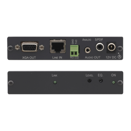
Page 13: Figure 7: Tp-124 Xga / Audio / Data Line Receiver (Topside)
Connects to the controlled unit LINE IN RJ-45 Connector Connects to the LINE OUT RJ-45 connector on the TP-121 XGA / Audio Line Transmitter or TP-104 XGA Line Transmitter / DA XGA OUT HD15F Connector Connect to the XGA acceptor ON LED... -
Page 14: Connecting The Xga / Audio Line Transmitter / Receiver
, on the underside 1 Not supplied. The complete list of Kramer cables is on our Web site at http://www.kramerelectronics.com 2 If you cannot connect the power to both the TP-121 and TP-122, you can just connect the power to the TP-122... -
Page 15: Figure 8: Connecting The Xga / Audio Line Transmitter / Receiver System
Connecting the XGA / Audio Line Transmitter / Receiver Figure 8: Connecting the XGA / Audio Line Transmitter / Receiver System KRAMER: SIMPLE CREATIVE TECHNOLOGY... -
Page 16: Wiring The Cat5 Line In / Line Out Rj-45 Connectors
Connecting the XGA / Audio Line Transmitter / Receiver 8.1 Wiring the CAT5 LINE IN / LINE OUT RJ-45 Connectors Table 8 and Figure 9 define the UTP CAT5 PINOUT, using a straight pin to pin cable with RJ-45 connectors: Figure 9: CAT5 PINOUT Table 8: CAT5 PINOUT EIA /TIA 568A... -
Page 17: Connecting The Xga / Audio / Data Line Transmitter / Receiver
, on the underside 1 Not supplied. The full list of Kramer cables is on our Web site at http://www.kramerelectronics.com. Alternatively, you can connect an XGA source to the XGA IN HD15F connector, and a separate audio source to the AUDIO IN 3.5mm mini jack 2 As defined in Figure 11 and Table 9 (see section 8.1) -
Page 18: Figure 10: Connecting The Xga / Audio / Data Line Transmitter / Receiver System
Connecting the XGA / Audio / Data Line Transmitter / Receiver Figure 10: Connecting the XGA / Audio / Data Line Transmitter / Receiver System... -
Page 19: Controlling Via Rs-232 (For Example, Using A Pc)
Figure 11 and Table 9: Figure 11: RS-232 PINOUT Connection Table 9: RS-232 PINOUT Connection Connect this PIN on the To this PIN on the Terminal Block Connector: DB9 Connector PIN 2 PIN 3 PIN 5 KRAMER: SIMPLE CREATIVE TECHNOLOGY... -
Page 20: Configuring A 1:4 Xga To Tp Transmitter / Receiver / Da
Configuring a 1:4 XGA to TP Transmitter / Receiver / DA 10 Configuring a 1:4 XGA to TP Transmitter / Receiver / DA You can use the TP-104 XGA Line Transmitter / DA with the TP-120 XGA Line Receiver to configure a 1:4 XGA-to-Twisted Pair DA system. -
Page 21: Figure 12: Configuring A 1:4 Xga To Twisted Pair Transmitter / Receiver / Da
Configuring a 1:4 XGA to TP Transmitter / Receiver / DA Figure 12: Configuring a 1:4 XGA to Twisted Pair Transmitter / Receiver / DA KRAMER: SIMPLE CREATIVE TECHNOLOGY... -
Page 22: Configuring A Tp-105 Cat5 Line Driver / Da
XGA OUT HD15F connector on the second TP-120 unit to the XGA acceptor (for example, Display 2) 4. On each of the four Kramer units, connect the 12V DC power adapter to the power socket and connect the adapter to the mains electricity. -
Page 23: Figure 13: Configuring A Tp-105 Cat5 Line Driver / Da
Configuring a TP-105 CAT5 Line Driver / DA Figure 13: Configuring a TP-105 CAT5 Line Driver / DA KRAMER: SIMPLE CREATIVE TECHNOLOGY... -
Page 24: Technical Specifications
Technical Specifications 12 Technical Specifications Table 10 includes the technical specifications of the TP-104, Table 11 includes the technical specifications of the TP-105, and Table 12 includes the technical specifications of the TP-121, TP-122, TP-123, and TP-124: Table 10: Technical Specifications of the TP-104 (with 60m CAT5 cable) -
Page 25: Table 12: Technical Specifications Of The Tp-121 / Tp-122 / Tp-123 / Tp-124
TND+N: AUDIO: <0.01% POWER SOURCE: 12 VDC 60mA DIMENSIONS: 12cm x 7.5cm x 2.5cm (4.7" x 2.95" x 0.98", W, D, H) WEIGHT: 0.3 kg. (0.67 lbs.) approx. ACCESSORIES: Power supply 1 For the Transmitter/Receiver pair KRAMER: SIMPLE CREATIVE TECHNOLOGY... - Page 26 EXCLUSION OF DAMAGES The liability of Kramer for any effective products is limited to the repair or replacement of the product at our option. Kramer shall not be liable for: Damage to other property caused by defects in this product, damages based upon inconvenience, loss of use of the product, loss of time, commercial loss;...
- Page 27 For the latest information on our products and a list of Kramer distributors, visit our Web site: www.kramerelectronics.com, where updates to this user manual may be found. We welcome your questions, comments and feedback. Safety Warning: Disconnect the unit from the power supply before opening/servicing.
Need help?
Do you have a question about the TP-104 and is the answer not in the manual?
Questions and answers