
Related Manuals for ADLINK Technology MI-220


Summary of Contents for ADLINK Technology MI-220
- Page 1 MI-220 Mini-ITX Embedded Motherboard with Intel® Core™ i7/i5/i3 CPU and QM67 PCH User’s Manual 2.01 Manual Rev.: December 19, 2011 Revision Date: 50-1Z086-1010 Part No: Advance Technologies; Automate the World.
- Page 2 Revision History Revision Release Date Description of Change(s) 2.00 2011/11/11 Initial release 2.01 2011/12/19 Correct F_PANEL1 pin definition Revision History...
-
Page 3: Preface
MI-220 Preface Copyright 2011 ADLINK Technology Inc. This document contains proprietary information protected by copy- right. All rights are reserved. No part of this manual may be repro- duced by any mechanical, electronic, or other means in any form without prior written permission of the manufacturer. - Page 4 Using this Manual Audience and Scope The MI-220 User’s Manual is intended for hardware technicians and systems operators with knowledge of installing, configuring and operating industrial grade computers. Manual Organization This manual is organized as follows: Preface: Presents copyright notifications, disclaimers, trade- marks, and associated information on the proper usage of this document and its associated product(s).
- Page 5 MI-220 Conventions Take note of the following conventions used throughout this manual to make sure that users perform certain tasks and instructions properly. Additional information, aids, and tips that help users perform tasks. NOTE: NOTE: Information to prevent minor physical injury, component dam- age, data loss, and/or program corruption when trying to com- plete a task.
- Page 6 This page intentionally left blank. Preface...
-
Page 7: Table Of Contents
MI-220 Table of Contents Revision History..............ii Preface ..................iii List of Figures ................ ix List of Tables................xi 1 Introduction ................ 1 Package Contents ............... 1 Overview................2 Features................2 Specifications............... 3 Block Diagram ..............5 Functional Description ............6 Power Consumption ............ - Page 8 4.3.2 CPU Configuration............37 4.3.3 SATA Configuration ............39 4.3.4 PCH-FW Configuration ..........40 4.3.5 AMT Configuration............41 4.3.6 USB Configuration ............44 4.3.7 Super IO Configuration ..........46 4.3.8 H/W Monitor..............49 4.3.9 Serial Port Console Redirection........50 Chipset Setup ..............54 4.4.1 System Agent (SA) Configuration........
-
Page 9: List Of Figures
MI-220 List of Figures Figure 1-1: MI-220 Block Diagram ............. 5 Figure 1-2: MI-220 Board Layout ............9 Figure 1-3: MI-220 Rear I/O Layout ..........10 Figure 1-4: MI-220 Board Dimensions ..........11 List of Figures... - Page 10 This page intentionally left blank. List of Figures...
-
Page 11: List Of Tables
List of Tables Table 1-1: MI-220 General Specifications......... 4 Table 1-2: Intel® Core™ i7-2710QE Power Consumption ....8 Table 1-3: MI-220 Board Layout Legend ........10 Table B-1: System Memory Map............. 69 Table B-2: Direct Memory Access Channels........70 Table B-3: Fixed I/O Map ..............71 Table B-4: Variable I/O Map............ - Page 12 This page intentionally left blank. List of Tables...
-
Page 13: Introduction
MI-220 Introduction This chapter will introduce the MI-220, its features, specifications, functional description, and mechanical layout. 1.1 Package Contents Please check that your package contains the items below. If you discover damaged or missing items, please contact your vendor. MI-220 Mini-ITX Embedded Motherboard... -
Page 14: Overview
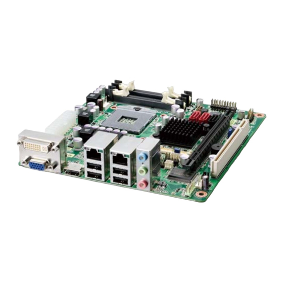
1.2 Overview The ADLINK MI-220 is a Mini-ITX embedded motherboard based on the Intel® Core™ i7/i5/i3 Processor built on 32-nm process technology in rPGA988B package and the Mobile Intel® QM67 Express Chipset. The MI-220 is ideal for embedded applications requiring low power consumption in a standard small form factor motherboard with a complete set of I/O functions and high-band- width network connectivity. -
Page 15: Specifications
MI-220 1.4 Specifications System Intel® Core™ Processor, rPGA988B package, Socket G2 • Core™ i7-2710QE, 2.1GHz, 6M LLC, 32nm, 45W TDP • Core™ i5-2510E, 2.5GHz, 3M LLC, 32nm, 35W TDP • Core™ i3-2330E, 2.2GHz, 3M LLC, 32nm, 35W TDP Intel® Celeron® B810, 1.6GHz, 2M LLC, 32nm, 35W TDP •... -
Page 16: Table 1-1: Mi-220 General Specifications
• 170 mm x 170 mm (L x W) Dimensions • 0°C to 60°C Operating Temp. • -20ºC to 80ºC Storage Temp. • 10 - 90% RH non-condensing Rel. Humidity • CE, FCC Class A Safety Table 1-1: MI-220 General Specifications Introduction... -
Page 17: Block Diagram
USB 2.0 PCIe x1 USB 2.0 Bridge (4x rear, 2x internal) XIO2001 Codec RS-232 (COM2-4) Fintek 81216AD PCI Slot Audio RS-232/422/ ALC892 485/485+ (COM1) SPI BIOS NCT6776F LPC Super I/O Hardware KB/Mouse 8-bit GPIO Monitor Figure 1-1: MI-220 Block Diagram Introduction... -
Page 18: Functional Description
1.6 Functional Description Processor Support The MI-220 is a Mini-ITX embedded board featuring the 2nd gen- eration Intel® Core™ processor family (Intel® Core™i7/i5/i3) in rPGA988B package. An integrated memory controller supports dual channel 1066/1333 MHz DDR3 and Intel® HD Graphics is integrated onboard the CPU. - Page 19 MI-220 Serial ATA The MI-220 provides three SATA ports with data transfer rates of up to 6.0 GB/s on 2 ports and up to 3.0 GB/s on 1 port. Intel® Rapid Storage Technology supports AHCI and RAID 0/1/5/10 functionality. USB 2.0 The MI-220 provides 6 USB 2.0 ports supporting transfer rates up...
-
Page 20: Power Consumption
1.7 Power Consumption Intel® Core™ i7-2710QE, 2.1GHz, 6M LLC, 32nm, 45W TDP Test Configuration Innodisk DDR3-1333 4GB M3SN-4GHJDC09-B (2x) Memory Intel® HD Graphics 3000 Graphics Seagate ST9160412AS Momentus 7200.4 160G. Storage SPI FSP350-60PLN 350W Power Supply DOS (idle) +12V +5VSB +3.3V Total Power Req. -
Page 21: Board Layout
MI-220 1.8 Board Layout DIMMA1 F_PANEL1 USB56 SPI_CN1 DIMMB1 SATA3 CPU_FAN1 SATA1/2 JLVDS1 ATXPWR1 JCLRTC2 COM2 COM4 JBKL1 JLPC1 COM1 COM3 JCASE1 KBMS1 DIO1 SYS_FAN1 JPSON1 AAFP1 Figure 1-2: MI-220 Board Layout Introduction... -
Page 22: Figure 1-3: Mi-220 Rear I/O Layout
SPDIF_OUT S/PDIF pin header JBKL1 Chassis Intrusion SPI pin header JCASE1 SPI_CN1 connector LCD Backlight Voltage USB4/5 pin header JCLRT_C2 USB45 jumper Clear CMOS jumper JCMOS1 Table 1-3: MI-220 Board Layout Legend LAN1 LAN2 HDMI Audio Figure 1-3: MI-220 Rear I/O Layout Introduction... -
Page 23: Mechanical Dimensions
MI-220 1.9 Mechanical Dimensions Dimensions in mm Figure 1-4: MI-220 Board Dimensions Introduction... - Page 24 This page intentionally left blank. Introduction...
-
Page 25: Connectors & Jumpers
MI-220 Connectors & Jumpers The connectors and jumpers on the MI-220 allow you to connect and configure external devices. Refer to Figure 1-2: MI-220 Board Layout and Figure 1-3: MI-220 Rear I/O Layout for con- nector and jumper locations. 2.1 Rear I/O Connectors VGA Connector. - Page 26 DVI-D Connector Pin # Signal Pin # Signal TMDS Data2- Hot Plug Detect TMDS Data2+ TMDS Data0- TMDS Data2/4 Shield TMDS Data0+ TMDS Data4- TMDS Data0/5 Shield TMDS Data4+ TMDS Data5- DDC Clock TMDS Data5+ DDC Data TMDS Clock Shield Analog Vertical Sync TMDS Clock + TMDS Data1-...
- Page 27 MI-220 LAN Port (RJ-45) This port allows gigabit connection to a Local Area Network (LAN) using a network hub. The LAN port comes with two LEDs to indi- cate link, activity and speed. Refer to the tables below for the LAN port pin and LED definitions.
-
Page 28: Onboard Connectors And Jumpers
2.2 Onboard Connectors and Jumpers Front Panel Audio Pin Header (AAFP1) Pin # Signal Pin # Signal MIC2_L MIC2_R 3.3V LIN2_R SRTN1 SENSE A LIN2_L SRTN2 ATX Power Connector (ATXPWR1) Pin # Signal Pin # Signal +3.3V +3.3V +3.3V -12V PS-ON# PWRGD +5VSB... - Page 29 MI-220 Serial Port Connectors - RS-232 (COM1~4) Pin # Signal Function Data Carrier Detect Data Set Ready Receive Data Request to Send Transmit Data Clear to Send Data Terminal Ready Ring Indicate Ground Serial Port Connector - RS-422/485/485+ (COM1) Pin #...
- Page 30 CPU Fan Connector (CPU__FAN) Pin # Signal Fan power (+12V) Fan Tachometer Fan Speed Control System Fan Connector (SYS_FAN) Pin # Signal Fan Power (+12V) Fan Tachometer Digital I/O Connector (DIO1) Pin # Signal Pin # Signal DIO_4 DIO_0 DIO_5 DIO_1 DIO_6 DIO_2...
- Page 31 The CMOS RAM data contains the date / time and BIOS setting information. CMOS is powered by the onboard button cell battery. To erase the CMOS RAM data: (1) Unplug the MI-220; (2) short the JP1 pin 2-3; (3) turn the power on. After power on, remove the jumper cap from pin 2-3 and reinstall it to pin 1-2.
- Page 32 Chassis Intrusion Connector (JCASE1) This header is connected to the chassis intrusion sensor to detect if the case is opened. Pin # Signal SIO_CASEOP# LVDS Flat Panel Connector (JLVDS1) Pin # Signal Pin # Signal +3.3V +3.3V SD_DDC SC_DDC LVDS0_P0 LVDS0_P1 LVDS0_N0 LVDS0_N1...
- Page 33 MI-220 LCD Inverter Connector (JBLK1) Pin # Signal +12V LVDS_BKL Bright LCD Backlight Voltage Jumper (JCLRT_C2) Status Connection JCLRT_C2 +5V (default) 1 – 2 2 – 3 LPC Pin Header (JLPC1) Pin # Signal Pin # Signal V3.3 BIOS_DISABLE# LPC_AD3...
- Page 34 AT Mode Jumper (JPSON1) Pin # Signal PSON_AT FRP_PANSWUN Status Connection JCLRT_C2 AT Mode 1 – 2 ATX Mode 2 – 3 (default) PS/2 Keyboard/Mouse Pin Header (KBMS1) Pin # Signal Function KDAT Keyboard data KCLK Keyboard clock MDAT Mouse data MCLK Mouse data P5V_KM...
- Page 35 MI-220 SPI Pin Header (SPI_CN1) Pin # Signal Pin # Signal +3V ROM F_SPI_CS# F_SPI_CLK F_SPI_MISO F_SPI_MOSI SPI_HOLD# USB 2.0 Connector (USB45) Pin # Signal Pin # Signal USB4- USB5- USB4+ USB5+ Connectors & Jumpers...
- Page 36 This page intentionally left blank. Connectors & Jumpers...
-
Page 37: Getting Started
This chapter provides information on how to install components to the MI-220 SBC. 3.1 System Memory The MI-220 supports up to 2 GB of DDR2 400/533 SDRAM in one 200-pin SO-DIMM socket. See Figure 1-2 on page 9 for the SO-DIMM socket location. -
Page 38: Driver Installation
3.2 Driver Installation The MI-220 drivers for Windows XP 32-bit are located in the fol- lowing directories on the Driver CD, or can be downloaded from the ADLINK website (http://www.adlinktech.com): X:\Driver\Step 1_CHIP\ Chipset X:\Driver\Step 2_VGA\winxp32 Display X:\Driver\Step 3_LAN\XP_32 X:\Driver\Step 4_AUDIO\XP 32_64... - Page 39 MI-220 6. Install the Intel Rapid Storage Technology Utility by extracting and running the program iata_cd_10.6.0.1022.exe in X:\Driver\Step 5_RAID\Intel_Rapid_Storage_Technology_ 10.6.0.1022.zip. Intel Rapid Storage Technology Utility file may not be included on the Driver CD. Please download it from the ADLINK website if necessary.
- Page 40 This page intentionally left blank. Getting Started...
-
Page 41: Bios Setup
MI-220 BIOS Setup The following chapter describes basic navigation for the AMIBIOS® EFI BIOS setup utility. 4.1 Starting the BIOS To enter the setup screen, follow these steps: 1. Power on the motherboard 2. Press the < Delete > key on your keyboard when you see the following text prompt: <... - Page 42 Setup Menu The main BIOS setup menu is the first screen that you can navi- gate. Each main BIOS setup menu option is described in this user’s guide. The Main BIOS setup menu screen has two main frames. The left frame displays all the options that can be configured.
- Page 43 MI-220 There is a hot key legend located in the right frame on most Note: setup screens. The < F8 > key on your keyboard is the Fail-Safe key. It is not dis- played on the key legend by default. To set the Fail-Safe settings of the BIOS, press the <...
- Page 44 The < F10 > key allows you to save any changes you have made and exit Setup. Press the < F10 > key to save your changes. The following screen will appear: Press the < Enter > key to save the configuration and exit. You can also use the <...
-
Page 45: Main Setup
MI-220 4.2 Main Setup When you first enter the Setup Utility, you will enter the Main setup screen. You can always return to the Main setup screen by select- ing the Main tab. There are two Main Setup options. They are described in this section. - Page 46 System Time/System Date Use this option to change the system time and date. Highlight Sys- tem Time or System Date using the < Arrow > keys. Enter new val- ues using the keyboard. Press the < Tab > key or the < Arrow > keys to move between fields.
-
Page 47: Advanced Bios Setup
MI-220 4.3 Advanced BIOS Setup Select the Advanced tab from the setup screen to enter the Advanced BIOS Setup screen. You can select any of the items in the left frame of the screen, such as SuperIO Configuration, to go to the sub menu for that item. -
Page 48: Acpi Settings
4.3.1 ACPI Settings ACPI Sleep State Select the highest ACPI sleep state the system will enter, when the SUSPEND button is pressed. Options: S1, S3, Suspend Disable. Resume On RTC Alarm Enable or disable system wake on alarm event. When enabled, the system will wake at the hr/min/sec specified. -
Page 49: Cpu Configuration
MI-220 4.3.2 CPU Configuration Hyper-Threading Enables/disables Intel® Hyper-Threading Technology. Active Processor Cores Number of cores to enable in processor. Options: All, 1. Limit CPUID Value Maximum When Enabled, the processor will limit the maximum CPUID input value to 03h when queried, even if the processor sup- ports a higher CPUID input value. - Page 50 feature flag to always return a zero (0). Options: Enabled, Dis- abled. Hardware Prefetcher Enables/disables the Mid Level Cache (L2) streamer prefetcher. Adjacent Cache Line Prefetch Enables/disables the prefetching of adjacent cache lines. Intel® Virtualization Tech When enabled, Intel® Virtualization Technology (Intel® VT) makes a single system appear as multiple independent sys- tems to software.
-
Page 51: Sata Configuration
MI-220 4.3.3 SATA Configuration SATA Controller(s) Enable or disable the SATA controller(s). SATA Mode Options: IDE, RAID, AHCI. BIOS Setup... -
Page 52: Pch-Fw Configuration
4.3.4 PCH-FW Configuration You can use this screen to enter the options for the Firmware Update Configuration Settings. The Firmware Update Configura- tion screen is shown below. Firmware Update Configuration ME FW Image Re-Flash Enable or disable eanagement Engine Firmware Image Re- Flash function. -
Page 53: Amt Configuration
MI-220 4.3.5 AMT Configuration You can use this screen to select options for the Intel Active Man- agement Technology settings. Intel AMT This item allows the user to Enable/Disable the Intel AMT func- tion. Intel AMT Setup Prompt Set the Intel AMT Setup Prompt to wait for hotkey to enter setup. - Page 54 Hide Un-Configure ME Confirmation Hide the Un-Configure ME prompt without password confirma- tion. MEBx Debug Message Output Enable or disable MEBx debug message output. Un-Configure ME This item allows the user to unprovision the ME function with- out a password. Options: Enabled, Disabled. Intel AMT Password Write Enable Enable or disable Intel AMT Password Write.
- Page 55 MI-220 OS Timer Sets the OS WatchDog Timer (seconds). BIOS Timer Sets the BIOS WatchDog Timer (seconds). BIOS Setup...
-
Page 56: Usb Configuration
4.3.6 USB Configuration Legacy USB Support Legacy USB Support refers to USB mouse and keyboard sup- port. Normally if this option is not enabled, any attached USB mouse or USB keyboard will not become available until a USB compatible operating system is fully booted with all USB driv- ers loaded. - Page 57 MI-220 EHCI Hand-Off This is a workaround for OSes without EHCI hand-off support. The EHCI ownership change should be claimed by EHCI driver. Options: Enable, Disable. Mass Storage Devices: Mass storage device emulation type. 'AUTO' enumerates devices according to their media format. Optical drives are emulated as 'CDROM', drives with no media will be emulated according to a drive type.
-
Page 58: Super Io Configuration
4.3.7 Super IO Configuration Serial Port1-4 Configuration Enter the submenu for each serial port to enable/disable and view the I/O port and IRQ settings. Serial Port Enable or disable Serial Port 1~4. BIOS Setup... - Page 59 MI-220 Device Settings Set the serial port address and IRQ. Options: Auto, IO=3F8h; IRQ=4, IO=3F8h; IRQ=3, 4, 5, 6, 7, 9. 10, 11, 12, IO=2F8h; IRQ=3, 4, 5, 6, 7, 9. 10, 11, 12, IO=3E8h; IRQ=3, 4, 5, 6, 7, 9.
- Page 60 Power Loss Determines what state the computer enters when AC power is restored after a power loss. The options for this value are Always Off, Always On and Auto. Always Off: Set this value to always power off the system while AC power is restored.
-
Page 61: H/W Monitor
MI-220 4.3.8 H/W Monitor This screen displays the current status of all of the monitored hardware devices/components such as voltages and tempera- tures. CPU Warning Temperature Enables or disables the CPU warning temperature function. Options: Disable, 50 C/122 F, 55 C/131, 60 C/140 F, 65 C/149 F, 70 C/158 F, 75 C/167 F. -
Page 62: Serial Port Console Redirection
4.3.9 Serial Port Console Redirection COM0/4 Console Redirection Options: Enabled/Disabled. BIOS Setup... - Page 63 MI-220 Console Redirection Settings The settings specify how the host computer and the remote com- puter exchange data. Both computers should have the same or compatible settings. Terminal Type This option is used to select either VT100/VT-UTF8 or ANSI terminal type. Options: VT100, VT100+, VT-UTF8, ASNI.
- Page 64 Stop Bits Stop bits indicate the end of a serial data packet. (A start bit indicates the beginning). The standard setting is 1 stop bit. Communication with slow devices may require more than 1 stop bit. Set this value to 1 and 2. Flow Control Set this option to select Flow Control for console redirection.
- Page 65 MI-220 Data Bits Displays the frame width for Out-of-Band Management. Parity Displays the parity for Out-of-Band Management. Stop Bits Displays the number of stop bits for Out-of-Band Management. Terminal Type VT-UTF8 is the preferred terminal type for out-of-band man- agement. The next best choice is VT100+ and then VT100.
-
Page 66: Chipset Setup
4.4 Chipset Setup Select the Chipset tab from the setup screen to enter the Chipset BIOS Setup screen. You can select any of the items in the left frame of the screen to go to the sub menu for that item. The Chip- set BIOS Setup screen is shown below. -
Page 67: System Agent (Sa) Configuration
MI-220 4.4.1 System Agent (SA) Configuration VT-d Intel Virtualization Technology for Directed I/O. Options: Enabled/ Disabled. Graphics Configuration Graphic Turbo IMON Current Graphic Turbo IMON Current values supported: 14-31 μA. Primary Display Allows you to select which graphics controller to use as the pri- mary boot device. - Page 68 GTT Size Set GTT (Graphics Memory Manager) size. Options:1MB, 2MB Aperture Size Options: 128MB, 256MB, 512MB DVMT Total Gfx Mem Select DVMT/Fixed memory size used by the Integrated Graphics Device. Options: 128MB, 256MB, Maximum. Gfx Low Power Mode Options: Enabled, Disabled LCD Control Primary IGFX Boot Display Select the display port active during POST.
- Page 69 MI-220 LCD Panel Type Select the LCD panel used by the internal graphic device. Options: VBIOS Default, 640x480 LVDS, 800x600 LVDS, 1024x768 LVDS, 1280x1024 LVDS, 1400x1050 LVDS1, 1400x1050 LVDS2, 1600x1200 LVDS, 1366x768 LVDS, 1680x1050 LVDS, 1920x1200 LVDS 1440x900 LVDS, 1600x900...
-
Page 70: Pci Express Configuration
4.4.2 PCI Express Configuration PEG0 - Gen X Configure PEG B0:D1:F0 Gen1-Gen2. Options: Auto, Gen1, Gen2. Always Enable PEG Options: Enabled, Disabled PEG ASPM Control ASPM support for the PEG device. Options: Disabled, Auto, ASPM L0s, ASPM L1, ASPM L0sL1 BIOS Setup... -
Page 71: Memory Configuration
MI-220 4.4.3 Memory Configuration Memory Frequency Maximum memory frequency in MHz. Options: Auto, 1067, 1333. BIOS Setup... -
Page 72: Pch-Io Configuration
4.4.4 PCH-IO Configuration LAN1/2 Controller Controls the onboard LAN1/2 controller. Options: Enabled/Dis- abled. LAN1/2 Option-ROM Enable or disable LAN1/2 Boot Option for legacy network devices. Wake on LAN1/2 from S5 Enable or disable wake on LAN1/2 from S5. Azalia Internal HDMI Codec Disabled: Azalia will be unconditionally Disabled. - Page 73 MI-220 BIOS Lock Enable or disable BIOS interface lockdown. GPIO Lock Enable or disable GPIO lockdown. USB Configuration EHCI1/2 Enable or disable the USB EHCI1/2 (USB 2.0) functions. BIOS Setup...
-
Page 74: Boot Configuration
4.5 Boot Configuration Select the Boot tab from the setup screen to enter the Boot BIOS Setup screen. You can select any of the items in the left frame of the screen, such as Boot Device Priority, to go to the sub menu for that item. - Page 75 MI-220 Option ROM Messages Set the display mode for Option ROM messages. Options: Force BIOS, Keep Current. Interrupt 19 Capture Allows Option ROMs to trap INT 19. Options: Disabled, Enabled. Set Boot Priorities The Boot devices are listed in groups by device type. First press <Enter>...
-
Page 76: Security Setup
4.6 Security Setup Administrator Password Select this option and press < Enter > to access the sub menu. You can use the sub menu to change the Administrator password. User Password Select this option and press < Enter > to access the sub menu. You can use the sub menu to change the User password. -
Page 77: Exit Menu
MI-220 4.7 Exit Menu Select the Exit tab from the setup screen to enter the Exit BIOS Setup screen. You can display an Exit BIOS Setup option by high- lighting it using the < Arrow > keys. The Exit BIOS Setup screen is shown below. - Page 78 Discard Changes and Exit Setup Now? [Yes] [No] appears in the window. Select [Yes] to discard changes and exit. Save Changes and Reset Reset the system after saving the changes. Discard Changes and Reset Reset system setup without saving any changes. Save Changes Save changes made so far to any of the setup options.
-
Page 79: A Appendix: Watchdog Timer
MI-220 Appendix A - Watchdog Timer Watchdog Timer sample code for the MI-220 is as follows. WDT Sample Code void SIOConfigEnter () IoWrite8 (NCT6776F_CONFIG_INDEX , NCT6776F_CONFIG_MODE_ENTER_VALUE); IoWrite8 (NCT6776F_CONFIG_INDEX , NCT6776F_CONFIG_MODE_ENTER_VALUE); void SIOConfigExit () IoWrite8 (NCT6776F_CONFIG_INDEX , NCT6776F_CONFIG_MODE_EXIT_VALUE); void Oem_WDT_Init (... - Page 80 IoWrite8 (NCT6776F_CONFIG_DATA , NCT6776F_LDN_GPIOA); IoWrite8 (NCT6776F_CONFIG_INDEX , 0xE0); selection Pin113 to GPO High IoWrite8 (NCT6776F_CONFIG_DATA , 0x00); IoWrite8 (NCT6776F_CONFIG_INDEX , 0xE1); IoWrite8 (NCT6776F_CONFIG_DATA , 0x01); IoWrite8 (NCT6776F_CONFIG_INDEX , 0xE5); selection Pin113 to WDTO IoWrite8 (NCT6776F_CONFIG_DATA , 0x01); IoWrite8 (NCT6776F_CONFIG_INDEX , 0x2C); Pin113 function selection to GPIOA0 Data8 = IoRead8(NCT6776F_CONFIG_DATA) &...
-
Page 81: B Appendix: System Resources
MI-220 Appendix B - System Resources B.1 System Memory Map Address Range Address Range Size Description (decimal) (hex) FFE00000 – (4GB-8MB) 8 MB High BIOS Area FFFFFFFF (4GB-18MB) – FEE00000 – 1 MB FSB Interrupt Memory Space (4GB-17MB-1) FEEFFFFF (4GB-20MB) –... -
Page 82: Direct Memory Access Channels
B.2 Direct Memory Access Channels Channel Number Data Width System Resource Open Open Open Open Direct Memory Access Controller Open Open Open Table B-2: Direct Memory Access Channels System Resources... -
Page 83: Fixed I/O Map
MI-220 B.3 Fixed I/O Map Hex Range Device 000-00F Direct memory access controller 010-01F Motherboard resources 020-021 Programmable interrupt controller 022-03F Motherboard resources 040-043 System timer 044-04F Motherboard resources 050-053 System timer 054-05F Motherboard resources 060-060 Standard 101/102-Key or Microsoft Natural PS/2... - Page 84 Hex Range Device 0F0-0FF Numeric data processor 274-277 ISAPNP Read Data Port 279-279 ISAPNP Read Data Port 290-29F Motherboard resources 3B0-3BB Intel HD Graphics Family 3C0-3DF Intel HD Graphics Family 400-453 Motherboard resources 454-457 Motherboard resources 458-47F Motherboard resources 4D0-4D1 Motherboard resources 500-57F Motherboard resources...
-
Page 85: Variable I/O Map
MI-220 Hex Range Device F0F0-F0FF Intel 6 Series/C220 Series Chipset Family 4 port Serial F100-F103 Intel 6 Series/C220 Series Chipset Family 4 port Serial F110-F117 Intel 6 Series/C220 Series Chipset Family 4 port Serial F120-F123 Intel 6 Series/C220 Series Chipset Family 4 port Serial... -
Page 86: Interrupt Request (Irq) Lines
B.5 Interrupt Request (IRQ) Lines IRQ Lines APIC Mode IRQ# Typical Interrupt Resource System timer Standard 101/102-Key or Microsoft Natural PS/2 Keyboard Communications Port (COM1) Communications Port (COM2) System CMOS/real time clock Microsoft ACPI-Compliant System Communications Port (COM3) Communications Port (COM4) Microsoft PS/2 Mouse Numeric data Processor Intel 6 Series/C220 Series Chipset Family SMBus Controller-... -
Page 87: Pci Configuration Space Map
MI-220 B.6 PCI Configuration Space Map Bus # Device # Function # Routing Description Intel QM67 Host Processor Bridge Internal Intel Integrated Graphics Device Internal Intel Management Engine Interface Internal KT Controller Internal GbE Controller Internal Intel USB EHCI Controller #2... -
Page 88: Pci Interrupt Routing Map
B.7 PCI Interrupt Routing Map Intel ME INTA INTD INTC INTB GbE Controller EHCI Controller #1 EHCI Controller #0 HDA Controller PCIE port 0 INTA INTB INTC INTD LPC Controller INTF INTC INTA SATA Controller0 SATA Controller1 SMBus Controller Table B-7: PCI Interrupt Routing Map System Resources... -
Page 89: Important Safety Instructions
MI-220 Important Safety Instructions For user safety, please read and follow all instructions, WARNINGS, CAUTIONS, and NOTES marked in this manual and on the associated equipment before handling/operating the equipment. Read these safety instructions carefully. Keep this user’s manual for future reference. - Page 90 Never attempt to fix the equipment. Equipment should only be serviced by qualified personnel. A Lithium-type battery may be provided for uninterrupted, backup or emergency power. Risk of explosion if battery is replaced with one of an incorrect type. Dispose of used batteries appropriately. WARNING: Equipment must be serviced by authorized technicians when:...
-
Page 91: Getting Service
5215 Hellyer Avenue, #110, San Jose, CA 95138, USA Tel: +1-408-360-0200 Toll Free: +1-800-966-5200 (USA only) Fax: +1-408-360-0222 Email: info@adlinktech.com ADLINK Technology (China) Co., Ltd. Address: (201203) 300 Fang Chun Rd., Zhangjiang Hi-Tech Park, Pudong New Area, Shanghai, 201203 China Tel: +86-21-5132-8988 Fax:... - Page 92 84 Genting Lane #07-02A, Cityneon Design Centre, Singapore 349584 Tel: +65-6844-2261 Fax: +65-6844-2263 Email: singapore@adlinktech.com ADLINK Technology Singapore Pte. Ltd. (Indian Liaison Office) Address: 1st Floor, #50-56 (Between 16th/17th Cross) Margosa Plaza, Margosa Main Road, Malleswaram, Bangalore-560055, India Tel: +91-80-65605817, +91-80-42246107 Fax: +91-80-23464606 Email: india@adlinktech.com...
Need help?
Do you have a question about the MI-220 and is the answer not in the manual?
Questions and answers