
Subscribe to Our Youtube Channel
Related Manuals for Eaton 9395XC


Summary of Contents for Eaton 9395XC
- Page 1 Eaton ® 9395XC UPS 1200kW/1200kVA, 1350kW/1350kVA or 1500kW/1500kVA, Installation and Operation Manual p/n: 164001079 Revision 01...
- Page 2 Eaton reserves the right to change specifications without prior notice. Eaton and Power Xpert are registered trademarks and PredictPulse is a trademark of Eaton or its subsidiaries and affiliates. CA Technologies is a registered trademark of CA, Inc. IBM and AS/400 are registered trademarks of International Business Machines Corporation.
- Page 3 Dear Customer, On behalf of everyone at Eaton, we thank you for partnering with us, and trusting us to maintain your business continuity and preventing downtime at your facility. Our suite of backup power, power distribution and power management products are designed to protect you from a host of threats including power outages, surges, lighting strikes, and enable you to monitor and control your power infrastructure.
- Page 4 Licensee or other subsidiary of Licensee’s parent, to copy, distribute, or otherwise transfer the Firmware without the prior written consent of Eaton. Licensee may transfer the Firmware directly to a third party only in connection with the sale of the Eaton product in which it is installed.
- Page 5 TO THE EXTENT PERMITTED BY APPLICABLE LAW, THE USE OF THE PRODUCT IS AT LICENSEE’S SOLE RISK. 5.0 GENERAL PROVISIONS 5.1 Update Policy. Eaton may from time to time, but has no obligation to, create Updates of the Firmware or components thereof. 5.2 Limitation on Liability. NOTWITHSTANDING ANY PROVISION OF THIS AGREEMENT TO THE...
- Page 6 Firmware pursuant to license arrangements between Eaton and such third parties. Third Party Licensor components in the Firmware are not licensed or warranted under the terms of this document, but are instead subject to the Third Party Licensors’...
- Page 7 Eaton, the disclosure of which would cause substantial harm to Eaton that could not be remedied by the payment of damages alone and such confidential aspects of the Firmware shall not be disclosed to third parties without the prior written consent of Eaton.
- Page 9 4.2 Unloading the UPS Cabinet from the Pallet..................... 41 4.3 Installing and Connecting the UPS Sections ....................47 4.3.1 Preparing the UPS Sections ........................47 4.3.2 Electrically Connecting the UPS Sections ....................50 Eaton 9395XC UPS 1200kW/1200kVA, 1350kW/1350kVA or 1500kW/1500kVA 164001079—Rev 01...
- Page 10 7 7 U U P P S S O O p p e e r r a a t t i i n n g g I I n n s s t t r r u u c c t t i i o o n n s s ................................................. . 1 1 0 0 1 1 7.1 UPS Controls ............................101 7.1.1 Control Panel ........................... 102 7.2 Touchscreen Control Panel ........................102 7.3 Using the Touchscreen Control Panel......................102 7.3.1 Touch Screen Controls........................104 Eaton 9395XC UPS 1200kW/1200kVA, 1350kW/1350kVA or 1500kW/1500kVA 164001079—Rev 01...
- Page 11 1 1 0 0 P P r r o o d d u u c c t t S S p p e e c c i i f f i i c c a a t t i i o o n n s s ................................................... . 1 1 3 3 9 9 10.1 Model Numbers ........................... 139 10.2 Specifications............................139 10.2.1 UPS Input............................139 Eaton 9395XC UPS 1200kW/1200kVA, 1350kW/1350kVA or 1500kW/1500kVA 164001079—Rev 01...
- Page 12 Table of Contents 10.2.2 UPS Output ........................... 140 10.2.3 UPS Environmental ......................... 140 10.2.4 Battery Run Time Ratings ......................... 141 Eaton 9395XC UPS 1200kW/1200kVA, 1350kW/1350kVA or 1500kW/1500kVA 164001079—Rev 01...
- Page 13 Terminal Blocks TB1, TB2, and TB3 Connector Assignments ..............67 Figure 36. Typical Battery Interface Connection ....................68 Figure 37. Minislot Communication Bays......................69 Figure 38. REPO Switch ..........................70 Figure 39. Normally-Open REPO Switch Wiring ....................71 Eaton 9395XC UPS 1200kW/1200kVA, 1350kW/1350kVA or 1500kW/1500kVA 164001079—Rev 01 xiii...
-
Page 14: Table Of Contents
Bypass Meters Screen ........................ 113 Figure 77. Output Meters Screen ........................ 114 Figure 78. Battery Meters Screen ........................ 114 Figure 79. Battery Meters Screen — Battery Control..................115 Figure 80. Control Screen Status ......................... 115 Eaton 9395XC UPS 1200kW/1200kVA, 1350kW/1350kVA or 1500kW/1500kVA 164001079—Rev 01... - Page 15 Figure 89. REPO Operation ........................128 Figure 90. Optional Minislot Cards ....................... 129 Figure 91. ISBM/PM Section Air Filter Locations ..................... 135 Figure 92. ISBM/PM Section Air Filter Replacement ..................136 Eaton 9395XC UPS 1200kW/1200kVA, 1350kW/1350kVA or 1500kW/1500kVA 164001079—Rev 01...
- Page 16 List of Figures Eaton 9395XC UPS 1200kW/1200kVA, 1350kW/1350kVA or 1500kW/1500kVA 164001079—Rev 01...
- Page 17 External Power Cable Terminations ....................29 Table 9. Supplied External Power Wiring Terminal and Cabinet to Cabinet Hardware Kit........... 30 Table 10. Recommended Installation Parts and Tools (Not Supplied by Eaton) ............31 Table 11. 480V Power Cable Conduit Recommendations ..................32 Table 12.
- Page 18 List of Tables xviii Eaton 9395XC UPS 1200kW/1200kVA, 1350kW/1350kVA or 1500kW/1500kVA 164001079—Rev 01...
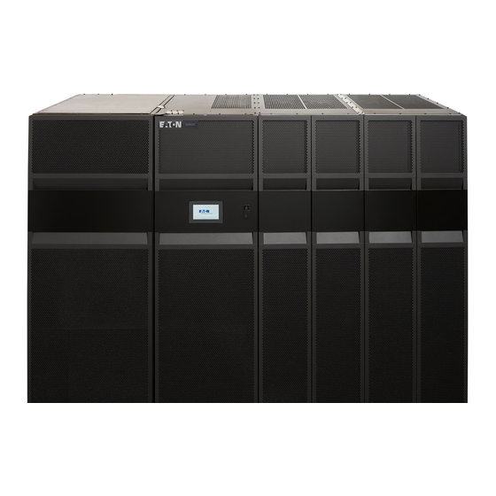
- Page 19 AC power to protect the customer's load from power failures. The Power Xpert 9395XC contains a section configured as an integrated system bypass module (ISBM) and power module (PM) rated for a maximum of 1500 kVA.
- Page 20 Introduction Figure 1. Eaton 9395XC UPS (LD) I/O SECTION ISBM/PM SECTION Eaton 9395XC UPS 1200kW/1200kVA, 1350kW/1350kVA or 1500kW/1500kVA 164001079—Rev 01...
- Page 21 The control panel, located on the front of the UPS is a 7-inch color touchscreen to control the operation of the UPS and to display the status of the UPS system. See Chapter 7 UPS Operating Instructions for additional information. Eaton 9395XC UPS 1200kW/1200kVA, 1350kW/1350kVA or 1500kW/1500kVA 164001079—Rev 01...
- Page 22 1 1 . . 2 2 . . 1 1 I I n n t t e e g g r r a a t t e e d d B B a a t t t t e e r r y y C C a a b b i i n n e e t t s s Battery backup protection can be provided by equipping the UPS system with Eaton 9395XC battery cabinets containing sealed lead-acid, maintenance-free batteries.
- Page 23 UPS from virtually any location within the facility, up to 300 feet from the UPS. Refer to the Eaton Remote Monitoring Device (RMD) Installation and Operation Manual, listed in paragraph...
- Page 24 F F o o r r M M o o r r e e I I n n f f o o r r m m a a t t i i o o n n Refer to the Eaton Remote Monitoring Device (RMD) Installation and Operation Manual for additional installation and operating instructions.
- Page 25 1 1 . . 9 9 W W a a r r r r a a n n t t y y To view the UPS warranty please click on the link or copy the address to download from the Eaton website: UPS Product Warranty https://www.eaton.com/content/dam/eaton/products/backup-power-ups-surge-it-power-distribution/backup-...
- Page 26 Introduction Eaton 9395XC UPS 1200kW/1200kVA, 1350kW/1350kVA or 1500kW/1500kVA 164001079—Rev 01...
- Page 27 Do not check UPS operation by any action that includes removal of the earth (ground) connection with loads attached. • Do not open or mutilate batteries. Released electrolyte is harmful to the skin and eyes. It may be toxic. Eaton 9395XC UPS 1200kW/1200kVA, 1350kW/1350kVA or 1500kW/1500kVA 164001079—Rev 01...
- Page 28 The operating environment should be maintained within the parameters stated in this manual. • Keep surroundings uncluttered, clean, and free from excess moisture. • Observe all DANGER, CAUTION, and WARNING notices affixed to the inside and outside of the equipment. Eaton 9395XC UPS 1200kW/1200kVA, 1350kW/1350kVA or 1500kW/1500kVA 164001079—Rev 01...
- Page 29 End forklift slots may be used for minor positioning if the forks are kept in a horizontal position with no upward angling. If these instructions are not followed, damage to the wiring channel and wiring will occur. Eaton 9395XC UPS 1200kW/1200kVA, 1350kW/1350kVA or 1500kW/1500kVA 164001079—Rev 01...
- Page 30 Les passages de fourche à l’extrémité de l’armoire peuvent servir lors des petits déplacements, et ce, si les fourches sont en position horizontale sans pointer vers le haut. Si ces instructions ne sont pas suivies, des dommages au câblage et à son canal surviendront. Eaton 9395XC UPS 1200kW/1200kVA, 1350kW/1350kVA or 1500kW/1500kVA 164001079—Rev 01...
- Page 31 Service Engineer, or the warranty terms specified on 1.9 Warranty become void. This service is offered as part of the sales contract for the UPS. Contact an Eaton service representative in advance (usually a two-week notice is required) to reserve a preferred startup date.
- Page 32 3 3 . . 2 2 . . 2 2 E E n n v v i i r r o o n n m m e e n n t t a a l l a a n n d d I I n n s s t t a a l l l l a a t t i i o o n n C C o o n n s s i i d d e e r r a a t t i i o o n n s s Make sure that the environment for the 9395XC UPS meets the following operating restrictions: The environmental requirements specified below are for the air at the intake ports of the 9395XC, and are the maximum, not to exceed, ratings.
- Page 33 Maximum Relative Humidity: 95%, non-condensing NOTE If Eaton battery cabinets are located in the same room as the UPS, the battery cabinet environmental requirements supercede the UPS requirements. Operating temperatures above the recommended range will result in decreased battery life and performance, and will reduce or void the battery warranty.
- Page 34 Eaton 9395XC 1350 kVA (9000 CFM) 1500 kW 480/480 93.85 (320.2) 1500 kVA Figure 3. UPS Cabinet Dimensions – HD (Front View) 1999 [78.7] 2688 [105.8] Dimensions are in millimeters [inches] Eaton 9395XC UPS 1200kW/1200kVA, 1350kW/1350kVA or 1500kW/1500kVA 164001079—Rev 01...
- Page 35 UPS Installation Plan and Unpacking Figure 4. UPS Cabinet Dimensions – LD (Front View) 1999 [78.7] 2918 [114.9] Dimensions are in millimeters [inches] Eaton 9395XC UPS 1200kW/1200kVA, 1350kW/1350kVA or 1500kW/1500kVA 164001079—Rev 01...
- Page 36 UPS Installation Plan and Unpacking Figure 5. Cabinet Dimensions (Right Side View) 801.5 [1.7] [31.6] 845.5 [33.3] Dimensions are in millimeters [inches] Eaton 9395XC UPS 1200kW/1200kVA, 1350kW/1350kVA or 1500kW/1500kVA 164001079—Rev 01...
- Page 37 UPS Installation Plan and Unpacking Figure 6. ISBM/PM Section Dimensions – (Front View) 1998.5 [78.7] 1927.5 [75.9] Dimensions are in millimeters [inches] Eaton 9395XC UPS 1200kW/1200kVA, 1350kW/1350kVA or 1500kW/1500kVA 164001079—Rev 01...
- Page 38 [75.9] 263.53 542.03 542.03 [21.3] [10.4] [21.3] Dimensions are in millimeters [inches] Figure 8. UPS Bottom View CONDUIT LANDING FOR AC INPUT AND OUTPUT AND DC INPUT I/O SECTION ISBM/PM SECTION Eaton 9395XC UPS 1200kW/1200kVA, 1350kW/1350kVA or 1500kW/1500kVA 164001079—Rev 01...
- Page 39 UPS Installation Plan and Unpacking Figure 9. I/O Section Dimensions – HD (Front View) 1999 [78.7] 136.23 Dress [30.0] [5.4] Skirt (Optional) I/O SECTION FRONT Dimensions are in millimeters [inches] Eaton 9395XC UPS 1200kW/1200kVA, 1350kW/1350kVA or 1500kW/1500kVA 164001079—Rev 01...
- Page 40 Figure 10. I/O Section Dimensions – (Top View) [1.2] 47.5 47.5 [36.6] [27.5] [1.9] [1.9] [28.5] [28.5] Front Front I/O SECTION TOP (LD) I/O SECTION TOP (HD) Dimensions are in millimeters [inches] Eaton 9395XC UPS 1200kW/1200kVA, 1350kW/1350kVA or 1500kW/1500kVA 164001079—Rev 01...
- Page 41 Dimensions are in millimeters [inches] DIMENSIONS MM [IN] CENTER OF GRAVITY 378.3 [14.9] 796.2 [31.3] 1551.6 [61.1] ISBM/PM CABINET 1043.7 [41.1] 325.5 [12.8] 978.6 [38.5] 393.8 [15.5] 742.3 [29.2] 477.1 [18.8] HD I/O CABINET Eaton 9395XC UPS 1200kW/1200kVA, 1350kW/1350kVA or 1500kW/1500kVA 164001079—Rev 01...
- Page 42 Dimensions are in millimeters [inches] DIMENSIONS MM [IN] CENTER OF GRAVITY 378.3 [14.9] 796.2 [31.3] 1724.1 [67.9] ISBM/PM CABINET 978.6 [38.5] 1043.7 [41.1] 325.5 [12.8] LD I/O CABINET 393.8 [15.5] 742.3 [29.2] 669.8 [26.4] Eaton 9395XC UPS 1200kW/1200kVA, 1350kW/1350kVA or 1500kW/1500kVA 164001079—Rev 01...
- Page 43 (from a Wye source) for proper equipment operation. • The Eaton 9395XC 480V unit is designed for operation on a grounded-wye source of supply. There is no additional connection point for a neutral conductor. The output of this UPS will not directly support phase to neutral loads.
- Page 44 UPSs or each UPS in distributed bypass and parallel systems must use a separate battery system for each UPS. The Eaton 9395XC UPS provides backfeed detection and protection through a UVR trip mechanism of the bypass input breaker. An optional I/O Cabinet is also available with an integrated backfeed contactor.
- Page 45 NOTE Callout letters A, B, C, and D map to Figure NOTE Bypass wiring data is not applicable to IOM configurations. Battery Conductor Sizing: Eaton strongly recommends using the specified DC conductor size and quantity shown above for optimum system performance and battery run time. Battery Cable Routing Requirements Conduit applications: * Each conduit must have a Positive, Negative, and Ground conductor.
- Page 46 Hex Bolt M10 x 25mm 180190078-087 AC Output Hex Nut I/O AC Input to ISBM 180200001-05 I/O AC Input to ISBM, Bypass Input, AC Conical Washer 180500037-080 Output, Mounting to Brackets Eaton 9395XC UPS 1200kW/1200kVA, 1350kW/1350kVA or 1500kW/1500kVA 164001079—Rev 01...
- Page 47 Table 9 for supplied external wiring terminal hardware, and Table 10 recommended installation parts and tools not supplied by Eaton Corporation. Figure 29 through Figure 31 show the location of the power cable terminals inside the UPS.
- Page 48 Hex Bolt, Locking M5 x 12 mm (joining strap) Cabinet to Cabinet System Ground Hardware Eaton Part Number Part Size Quantity Hex Bolt M8 x 25mm 180190078-067 Flat Washer 180500036-080 Conical Washer 180500037-080 Eaton 9395XC UPS 1200kW/1200kVA, 1350kW/1350kVA or 1500kW/1500kVA 164001079—Rev 01...
- Page 49 UPS Installation Plan and Unpacking Table 10. Recommended Installation Parts and Tools (Not Supplied by Eaton) Quantity Manufacturer Part Number Notes Part Size 2/0 AWG Thomas & Betts 54862BE 3/0 AWG Thomas & Betts 54864BE 4/0 AWG Thomas & Betts...
- Page 50 Wiring Requirements. External overcurrent protection and disconnect are not provided by this product, but are required by codes. Refer to Table 5 If an output lockable disconnect is required, it is to be supplied by the customer. Eaton 9395XC UPS 1200kW/1200kVA, 1350kW/1350kVA or 1500kW/1500kVA 164001079—Rev 01...
- Page 51 Eaton 9395XC-1500/1500 2500A There is no manual DC disconnect device within the UPS. A battery disconnect switch is required for battery systems and may also be required by NEC or local codes. Eaton 9395XC UPS 1200kW/1200kVA, 1350kW/1350kVA or 1500kW/1500kVA 164001079—Rev 01...
- Page 52 Vdc, 20 mA minimum) connected between the alarm input and common terminal. All control wiring and relay and switch contacts are customer-supplied and may need to use Class 1 wiring, see above. • The building alarms can be programmed to display the alarm functional name. Eaton 9395XC UPS 1200kW/1200kVA, 1350kW/1350kVA or 1500kW/1500kVA 164001079—Rev 01...
- Page 53 Alarm relay wiring should be a minimum of 22 AWG. NOTE 1 On all 9395XC models that will be fed by a site generator at any time it is recommended to have an “On Generator” sensing input connected and proven functional. This allows the UPS to optimize its operation with the generator.
- Page 54 • The 9395XC unit is designed for operation on a ground wire source of supply. There is no additional connection point for a neutral conductor. The output of this UPS will not directly support phase to neutral loads.
- Page 55 Si ces instructions ne sont pas suivies, des dommages au câblage et à son canal surviendront. Carefully inspect the outer packaging for evidence of damage during transit. Do not install a damaged cabinet. Report any damage to the carrier and contact an Eaton service representative immediately.
- Page 56 Inspect the contents for any evidence of physical damage, and compare each item with the Bill of Loading. If damage has occurred or shortages are evident, contact an Eaton service representative immediately to determine the extent of the damage and its impact on further installation.
- Page 57 UPS Installation Plan and Unpacking Figure 15. UPS Cabinet as Shipped on Pallet (I/O Section) Eaton 9395XC UPS 1200kW/1200kVA, 1350kW/1350kVA or 1500kW/1500kVA 164001079—Rev 01...
- Page 58 UPS Installation Plan and Unpacking Eaton 9395XC UPS 1200kW/1200kVA, 1350kW/1350kVA or 1500kW/1500kVA 164001079—Rev 01...
- Page 59 Les sections de l’onduleur sont lourdes (voir le Table 2). Suivre attentivement les instructions de déchargement et de déballage pour éviter de renverser les armoires, ce qui pourrait causer de graves blessures. Eaton 9395XC UPS 1200kW/1200kVA, 1350kW/1350kVA or 1500kW/1500kVA 164001079—Rev 01...
- Page 60 (see for cabinet weight). If installed, remove the optional dress skirts at the bottom of the I/O and ISBM/PM cabinets (see Figure 16 Figure 18). To remove the pallet and mechanically install the UPS: Eaton 9395XC UPS 1200kW/1200kVA, 1350kW/1350kVA or 1500kW/1500kVA 164001079—Rev 01...
- Page 61 17). Remove the right side shipping bracket. Figure 16. Removing the ISBM/PM Section Left Side Shipping Bracket Front Door Dress Skirt (Three sides, Optional) Shipping Bracket Pallet Bolts Shipping Bracket Left Side Shipping Bolts Bracket Eaton 9395XC UPS 1200kW/1200kVA, 1350kW/1350kVA or 1500kW/1500kVA 164001079—Rev 01...
- Page 62 Pull the pallet from under the cabinet. Discard or recycle the pallet and shipping brackets in a responsible manner. Carefully lower the cabinet until the cabinet base contacts the floor. Repeat Steps 2 through 6 for the I/O cabinet (see Figure 18 Figure 19 Eaton 9395XC UPS 1200kW/1200kVA, 1350kW/1350kVA or 1500kW/1500kVA 164001079—Rev 01...
- Page 63 UPS System Installation Figure 18. Removing the I/O Section Left Side Shipping Bracket Front Panel Shipping Bracket Bolts Pallet Shipping Bracket Bolts Left Side Shipping Bracket Eaton 9395XC UPS 1200kW/1200kVA, 1350kW/1350kVA or 1500kW/1500kVA 164001079—Rev 01...
- Page 64 UPS System Installation Figure 19. Removing the I/O Section Right Side Shipping Bracket Front Panel Shipping Bracket Bolts Pallet Shipping Bracket Right Side Shipping Bolts Bracket Eaton 9395XC UPS 1200kW/1200kVA, 1350kW/1350kVA or 1500kW/1500kVA 164001079—Rev 01...
- Page 65 Use care during installation to protect components mounted on the right side of the I/O section and the inter- cabinet wiring harnesses attached to the left side ISBM/PM section from damage. Eaton 9395XC UPS 1200kW/1200kVA, 1350kW/1350kVA or 1500kW/1500kVA 164001079—Rev 01...
- Page 66 Lors de l’installation, prendre soin de protéger les composantes du côté droit de la section d'entrée/sortie (I/O) et les faisceaux de câbles reliant les armoires du côté gauche du module de contournement de système intégré (ISBM). Eaton 9395XC UPS 1200kW/1200kVA, 1350kW/1350kVA or 1500kW/1500kVA 164001079—Rev 01...
- Page 67 Remove the retaining screw located inside the door at the bottom hinge pivot point, then lift the door off. • Retain the hardware for later use. Remove the deadfront panels from the I/O and ISBM/PM sections (see Figure 21). Proceed to paragraph 4.3.2 Electrically Connecting the UPS Sections Eaton 9395XC UPS 1200kW/1200kVA, 1350kW/1350kVA or 1500kW/1500kVA 164001079—Rev 01...
- Page 68 ISBM section. The shipping brackets can be removed and discarded after releasing the power wiring. Disconnect the power wiring harnesses from the ISBM shipping brackets (see Figure 23). Eaton 9395XC UPS 1200kW/1200kVA, 1350kW/1350kVA or 1500kW/1500kVA 164001079—Rev 01...
- Page 69 C cable lug connections to the I/O AC Input terminals. Follow the callout details in Figure 23 to connect the correct cable lug to the proper terminals. See paragraph 3.2.4 UPS System Power Wiring Preparation wiring and termination requirements. Eaton 9395XC UPS 1200kW/1200kVA, 1350kW/1350kVA or 1500kW/1500kVA 164001079—Rev 01...
- Page 70 PM section left side and the front of the cabinet bases are flush with each other. Make sure to align the connecting bolt holes in the I/O base and the joining strap on the upper ISBM section (see Figure 24 Eaton 9395XC UPS 1200kW/1200kVA, 1350kW/1350kVA or 1500kW/1500kVA 164001079—Rev 01...
- Page 71 (see Figure 24). Align the holes on the joining strap between the I/O and ISBM/PM sections. Secure the bracket with five M5 bolts from the hardware kit (see Figure 25). Eaton 9395XC UPS 1200kW/1200kVA, 1350kW/1350kVA or 1500kW/1500kVA 164001079—Rev 01...
- Page 72 Connect the ground cable from the ISBM/PM to the I/O section ground points using the supplied hardware (see Figure 26 Table 9). Route the cable through the ground access hole in the I/O section (see Figure 23). Eaton 9395XC UPS 1200kW/1200kVA, 1350kW/1350kVA or 1500kW/1500kVA 164001079—Rev 01...
- Page 73 27). Do not remove the debris shields until installation is complete. However, remove the shields before operating the UPS. Once the debris shields are removed, do not place objects on the ventilation grills. Eaton 9395XC UPS 1200kW/1200kVA, 1350kW/1350kVA or 1500kW/1500kVA 164001079—Rev 01...
- Page 74 Pull the wiring through conduit into the wiring area. Retain all panel hardware. Figure 27. ISBM and ISBM/PM Section Debris Shields Debris Shields Front I/O SECTION ISBM/PM SECTION Eaton 9395XC UPS 1200kW/1200kVA, 1350kW/1350kVA or 1500kW/1500kVA 164001079—Rev 01...
- Page 75 (E1, E2, E3) in the I/O section (see Figure 30 Figure 31. See paragraph 3.2.4 UPS System Power Wiring Preparation System Power Wiring Preparation for wiring and termination requirements. Eaton 9395XC UPS 1200kW/1200kVA, 1350kW/1350kVA or 1500kW/1500kVA 164001079—Rev 01...
- Page 76 Power Terminal Detail BB) Bypass Input: E6, E7, E8 UPS Output: E9, E10, E11 DC Input from (See gure UPS Battery Input (+), E4 Power Terminal Detail AA) Battery Output (-) E5 I/O FRONT Eaton 9395XC UPS 1200kW/1200kVA, 1350kW/1350kVA or 1500kW/1500kVA 164001079—Rev 01...
- Page 77 4 4 . . 6 6 . . 2 2 B B a a t t t t e e r r y y P P o o w w e e r r W W i i r r i i n n g g When sizing the battery system, do not exceed the internal battery charger capabilities. See Chapter 10 Product Specifications for maximum battery charger currents. Eaton 9395XC UPS 1200kW/1200kVA, 1350kW/1350kVA or 1500kW/1500kVA 164001079—Rev 01...
- Page 78 Chapter 10 Product Specifications sur les notices techniques pour connaître les tensions maximales du chargeur de batteries. Ne pas installer une armoire endommagée. Signaler les dommages au transporteur et communiquer avec un représentant du service Eaton immédiatement. To install wiring to connections: NOTE Battery Cable Routing Requirements using Conduit: •...
- Page 79 4.6.1 External Power Wiring Installation Step 2 and secure with the retained hardware. Reinstall the panels removed in paragraph 4.6.1 External Power Wiring Installation, Step 1 and secure with the retained hardware. Eaton 9395XC UPS 1200kW/1200kVA, 1350kW/1350kVA or 1500kW/1500kVA 164001079—Rev 01...
- Page 80 4.7.2 TB1 Battery Interface Connections; if wiring the Minislot connections only, proceed to paragraph 4.7.3 Minislot Connections; otherwise, proceed to Step 10. 10. Reinstall the ISBM deadfront panel and secure with the retained hardware. Eaton 9395XC UPS 1200kW/1200kVA, 1350kW/1350kVA or 1500kW/1500kVA 164001079—Rev 01...
- Page 81 Minislot-Slot Communication Bays (See Figure “Terminal Blocks TB1, TB2, and TB3 (See Figure “Minislot-Slot Communication Bays” Connector Assignments” for terminal assignments.) for detail.) Minislot Panel K5 Backfeed Contactor (LD option) ISBM/PM Eaton 9395XC UPS 1200kW/1200kVA, 1350kW/1350kVA or 1500kW/1500kVA 164001079—Rev 01...
- Page 82 UPS System Installation Figure 33. Minislot Wire Entry Wire Entry (ref) Eaton 9395XC UPS 1200kW/1200kVA, 1350kW/1350kVA or 1500kW/1500kVA 164001079—Rev 01...
- Page 83 Output: 3-Phase UPS Output Voltage to Sync Box for Sync Control. Out VOLT ØB Out VOLT ØC BYP VOLT RTRN ØA Input: 3-Phase Synchronization Source sent from Sync Box for Sync Control. Eaton 9395XC UPS 1200kW/1200kVA, 1350kW/1350kVA or 1500kW/1500kVA 164001079—Rev 01...
- Page 84 NOTE Alarm relay normally-open and normally-closed return terminals are separated on the terminal board but are electrically in common. NOTE Do not directly connect relay contacts to the mains related circuits. Reinforced insulation to the mains is required. NOTE Alarm relay wiring should be a minimum of 22 AWG Eaton 9395XC UPS 1200kW/1200kVA, 1350kW/1350kVA or 1500kW/1500kVA 164001079—Rev 01...
- Page 85 (see Figure To locate the appropriate terminals and review the wiring and termination requirements, see paragraph 3.2.4 UPS System Power Wiring Preparation, Table 16, and Figure 32 through Figure Eaton 9395XC UPS 1200kW/1200kVA, 1350kW/1350kVA or 1500kW/1500kVA 164001079—Rev 01...
- Page 86 Reinstall the interface entry plates and install the conduit. NOTE The 9395XC system can trip a maximum of six battery cabinets total. This applies to both the 1085 standard and High Rate series batteries. If more than six battery cabinets in total are needed in a separate UPM battery configuration, DO NOT hook up the UVRs.
- Page 87 4.2 Unloading the UPS Cabinet from the Pallet through 4.7 Installing Interface Connections. NOTE When installing the REPO switch, you must install conduit between the device and the UPS cabinet for wiring the switch. Eaton 9395XC UPS 1200kW/1200kVA, 1350kW/1350kVA or 1500kW/1500kVA 164001079—Rev 01...
- Page 88 The REPO switch must be a normally-open or normally-closed latching-type switch not tied into any other circuits. NOTE This procedure is intended to be used for the installation of the Eaton-supplied REPO switch. If installing another manufacturer's switch, use this procedure only as a guide. NOTE The REPO switch wiring must be in accordance with NEC Article 725 Class 2 requirements.
- Page 89 NEC Article 725 Class 2 requirements. 13. Reinstall the top Interface entry conduit landing panel and secure with the retained hardware. 14. Reinstall the front door removed in Step 4 and secure with the retained hardware. Eaton 9395XC UPS 1200kW/1200kVA, 1350kW/1350kVA or 1500kW/1500kVA 164001079—Rev 01...
-
Page 90: Figure 40. Normally Closed Repo Switch Wiring
REPO switch must be a latching-type switch not tied to any other circuits. NOTE REPO normally-open and normally-closed return terminals are separated on the terminal board but are electrically in common. Eaton 9395XC UPS 1200kW/1200kVA, 1350kW/1350kVA or 1500kW/1500kVA 164001079—Rev 01... -
Page 91: Figure 41. Normally Closed And Normally Open Repo Switch Wiring
1.9 Warranty become void. This service is offered as part of the sales contract for the UPS. Contact an Eaton service representative in advance (usually a two-week notice is required) to reserve a preferred startup date. 4 4 . . 1 1 1 1 C C o o m m p p l l e e t t i i n n g g t t h h e e I I n n s s t t a a l l l l a a t t i i o o n n C C h h e e c c k k l l i i s s t t The final step in installing the UPS system is completing the following Installation Checklist. - Page 92 Pull-chain wiring between the UPS cabinets is properly installed. o Adequate workspace exists around the UPS cabinets, the tie cabinet, and other cabinets. o Startup and operational checks are performed by an authorized Eaton Customer Service Engineer. Eaton 9395XC UPS 1200kW/1200kVA, 1350kW/1350kVA or 1500kW/1500kVA 164001079—Rev 01...
- Page 93 Accessories are mounted in installed locations and wiring is terminated inside the UPS cabinet. (OPTIONAL) o The debris shield covering the UPS cabinet ventilation grill is removed. o Startup and operational checks are performed by an authorized Eaton Customer Service Engineer. Eaton 9395XC UPS 1200kW/1200kVA, 1350kW/1350kVA or 1500kW/1500kVA 164001079—Rev 01...
- Page 94 UPS System Installation Notes _________________________________________________________________________ _________________________________________________________________________ _________________________________________________________________________ _________________________________________________________________________ _________________________________________________________________________ _________________________________________________________________________ _________________________________________________________________________ _________________________________________________________________________ _________________________________________________________________________ _________________________________________________________________________ _________________________________________________________________________ _________________________________________________________________________ _________________________________________________________________________ _________________________________________________________________________ _________________________________________________________________________ Eaton 9395XC UPS 1200kW/1200kVA, 1350kW/1350kVA or 1500kW/1500kVA 164001079—Rev 01...
- Page 95 Use only 75°C copper wire. The procedures in this section describe the installation of Distributed Bypass Control wiring for: • Controller Area Network (CAN) • Pull Chain wiring with Module Output Breakers (MOBs). Eaton 9395XC UPS 1200kW/1200kVA, 1350kW/1350kVA or 1500kW/1500kVA 164001079—Rev 01...
-
Page 96: Figure 42. External Interface Terminals Detail
If not already opened, open the front door and swing the door open (see Figure 16). Remove an Interface Entry Conduit Landing panel to drill or punch holes (see Figure 28). Reinstall the conduit landing panel and install the conduit. Eaton 9395XC UPS 1200kW/1200kVA, 1350kW/1350kVA or 1500kW/1500kVA 164001079—Rev 01... - Page 97 CN13 (GND-ISO) CN13 (GND-ISO) CN13 (GND-ISO) CN13 (GND-ISO) (Shared) (Shared) CN13 (CANBL) CN13 (CANBL) CN13 (CANBL) CN13 (CANBL) (Shared) (Shared) CN13 (CANBH) CN13 (CANBH) CN13 (CANBH) CN13 (CANBH) (Shared) (Shared) (Shared) Eaton 9395XC UPS 1200kW/1200kVA, 1350kW/1350kVA or 1500kW/1500kVA 164001079—Rev 01...
-
Page 98: Figure 43. Distributed Bypass System Can Interface Wiring
Table 21. Pull-Chain Wiring Terminations with MOBs From Function UPS 1 CN5 – BLD ALARM 5 RTN MOB 1 AUX 1 COM MOB Open Alarm UPS 1 CN5 – BLD ALARM 5 MOB 1 AUX 1 NC Eaton 9395XC UPS 1200kW/1200kVA, 1350kW/1350kVA or 1500kW/1500kVA 164001079—Rev 01... - Page 99 MOB 4 AUX 1 NC UPS 4 J19 – PULL CHAIN/REM EPO MOB 4 AUX 2 COM Pull Chain Common UPS 4 J19 – PULL CHAIN MOB 4 AUX 2 NO Pull Chain Eaton 9395XC UPS 1200kW/1200kVA, 1350kW/1350kVA or 1500kW/1500kVA 164001079—Rev 01...
-
Page 100: Figure 44. Distributed Bypass Pull-Chain Wiring With Mobs
Wire the connectors to the wires and connect to the applicable terminals (see Table Reinstall all panels previously removed and secure with the retained hardware. Close the UPS front doors and secure the latches. Eaton 9395XC UPS 1200kW/1200kVA, 1350kW/1350kVA or 1500kW/1500kVA 164001079—Rev 01... -
Page 101: Figure 45. Main Elements Of The Ups System
U U P P S S S S y y s s t t e e m m O O v v e e r r v v i i e e w w The Eaton Power Xpert 9395XC UPS is a continuous-duty, solid-state, transformerless (at 480 Vac), three- phase, true online system that provides conditioned and uninterruptible AC power to the UPS system's output and critical load. - Page 102 6 6 . . 2 2 . . 1 1 M M o o d d e e s s The 9395XC UPS supports a critical load in different modes of operation: • In Online mode, the critical load is supplied by the inverter, which derives its power from rectified utility AC power.
-
Page 103: Figure 46. Path Of Current Through The Ups In Online Mode
ESS mode is a normal operating mode, and not an alarm condition. While the UPS is in this mode, the Online light on the front display will illuminate. Eaton 9395XC UPS 1200kW/1200kVA, 1350kW/1350kVA or 1500kW/1500kVA 164001079—Rev 01... -
Page 104: Figure 47. Path Of Current Through The Ups In Bypass Mode
Les charges critiques ne sont pas protégées des fluctuations de tension ou de fréquence ni des pannes de courant lorsque l’onduleur est en mode Contournement. The Eaton 9395XC UPS provides backfeed detection and protection through a UVR mechanism of the bypass input breaker. An optional Bypass Contactor is available in the I/O Cabinet. -
Page 105: Figure 48. Path Of Current Through The Ups In Battery Mode
Bypass Input Switch Rectifier Output Input f i t r e i r e t Battery Converter Main Power Flow Breakers Contactors Trickle Current Closed Battery Breaker Energized Open De-Energized Battery Eaton 9395XC UPS 1200kW/1200kVA, 1350kW/1350kVA or 1500kW/1500kVA 164001079—Rev 01... - Page 106 Key K-ML must be inserted in the Load Bank breaker lock of the system to be connected to the load bank. Turn key K-LB to unlock the LBB breaker. Close the LBB breaker. Eaton 9395XC UPS 1200kW/1200kVA, 1350kW/1350kVA or 1500kW/1500kVA 164001079—Rev 01...
- Page 107 UPS Model Figure 49 Eaton 9395XC Single Reverse Transfer UPS – Two PM, Common Rectifier Feed, Common Battery, Dual-Feed Configuration Figure 50 Eaton 9395XC Simplified Dual-Feed UPS with Maintenance Bypass Panel Eaton 9395XC UPS 1200kW/1200kVA, 1350kW/1350kVA or 1500kW/1500kVA 164001079—Rev 01...
-
Page 108: Figure 49. One Pm, Common Rectifier Feed, Common Battery, Dual-Feed Configuration
NOTE AC input to recti er is not used in single feed con guration. Dashed lines indicate optional features/components NOTE Customer supplied bypass input breaker with 48-60VDC UVR is required unless I/O cabinet with Bypass Contactor is selected. Eaton 9395XC UPS 1200kW/1200kVA, 1350kW/1350kVA or 1500kW/1500kVA 164001079—Rev 01... -
Page 109: Figure 50. Simplified Dual-Feed Ups With Maintenance Bypass Panel
(BIB) is installed in the maintenance bypass and a single-feed UPS is being installed, a single feed to the maintenance bypass is acceptable for supplying both the UPS and the bypass. Eaton 9395XC UPS 1200kW/1200kVA, 1350kW/1350kVA or 1500kW/1500kVA 164001079—Rev 01... - Page 110 6 6 . . 4 4 . . 1 1 M M u u l l t t i i p p l l e e U U P P S S P P a a r r a a l l l l e e l l S S y y s s t t e e m m M M o o d d e e s s Similar to the single UPS system, the 9395XC UPS parallel system supports a critical load in five different modes of operation.
-
Page 111: Figure 51. Path Of Current Through The Upss In Online Mode - Distributed Bypass
If a module is taken offline, the other modules remain online to support the load. If more modules than can support the load must be taken offline, the load must be transferred to maintenance bypass or shut down. Eaton 9395XC UPS 1200kW/1200kVA, 1350kW/1350kVA or 1500kW/1500kVA 164001079—Rev 01... -
Page 112: Figure 52. Path Of Current Through The Upss In Bypass Mode - Distributed Bypass
(Online and On Battery), and create an entry into the alarm event history. As the battery discharges, the boost converter and inverter constantly make minute adjustments maintaining a steady output. The UPSs remain in Eaton 9395XC UPS 1200kW/1200kVA, 1350kW/1350kVA or 1500kW/1500kVA 164001079—Rev 01... -
Page 113: Figure 53. Path Of Current Through The Upss In Battery Mode - Distributed Bypass
The distributed bypass system oneline drawings in this section show the simplified internal structure of the UPS, battery supply, and basic maintenance bypass in a multiple UPS configuration. These onelines represent each UPS in the distributed bypass system. Eaton 9395XC UPS 1200kW/1200kVA, 1350kW/1350kVA or 1500kW/1500kVA 164001079—Rev 01... - Page 114 Multiple UPS – Distributed Bypass, Continuous Static Switch, Eaton 9395XC-1350/1350 2+1 and 3+0 Configurations Eaton 9395XC-1200/1200 Figure 56 Eaton 9395XC-1500/1500 Multiple UPS – Distributed Bypass, Continuous Static Switch, Eaton 9395XC-1350/1350 3+1 and 4+0 Configurations Eaton 9395XC-1200/1200 Eaton 9395XC UPS 1200kW/1200kVA, 1350kW/1350kVA or 1500kW/1500kVA 164001079—Rev 01...
-
Page 115: Figure 54. Typical Distributed Bypass System - Continuous Static Switch, 1+1 And 2+0 Configurations
– AC Input to Bypass – DC Input from Battery – UPS AC Output to Tie Cabinet – Output to Critical Load – Overcurrent Protection supplied by customer AC Output to Critical Load Eaton 9395XC UPS 1200kW/1200kVA, 1350kW/1350kVA or 1500kW/1500kVA 164001079—Rev 01... -
Page 116: Figure 55. Typical Distributed Bypass System -Continuous Static Switch, 2+1 And 3+0 Configurations
– AC Input to Bypass – DC Input from Battery – UPS AC Output to Tie Cabinet – Output to Critical Load – Overcurrent Protection supplied by customer AC Output to Critical Load Eaton 9395XC UPS 1200kW/1200kVA, 1350kW/1350kVA or 1500kW/1500kVA 164001079—Rev 01... -
Page 117: Figure 56. Typical Distributed Bypass System -Continuous Static Switch, 3+1 And 4+0 Configurations
– AC Input to Bypass – DC Input from Battery – UPS AC Output to Tie Cabinet – Output to Critical Load – Overcurrent Protection supplied by customer AC Output to Critical Load Eaton 9395XC UPS 1200kW/1200kVA, 1350kW/1350kVA or 1500kW/1500kVA 164001079—Rev 01... - Page 118 Understanding UPS Operation Eaton 9395XC UPS 1200kW/1200kVA, 1350kW/1350kVA or 1500kW/1500kVA 164001079—Rev 01...
-
Page 119: Figure 57. Ups Controls
The controls identified and described in this section are used to control and monitor UPS operation. Figure 57 Identifies the location of the touchscreen control panel. Figure 57. UPS Controls Control Panel Touchscreen Eaton 9395XC UPS 1200kW/1200kVA, 1350kW/1350kVA or 1500kW/1500kVA 164001079—Rev 01... -
Page 120: Figure 58. Ups Control Panel (Typical)
When power is supplied to the UPS, the control panel touchscreen boots and the Eaton logo appears. If the user is not logged in a Tap to Unlock screen appears (see Figure 59 Eaton 9395XC UPS 1200kW/1200kVA, 1350kW/1350kVA or 1500kW/1500kVA 164001079—Rev 01... -
Page 121: Figure 59. Tap To Unlock Screen
USER + CONTROL + CONFIGURATION + SERVICE The number in an unlocked padlock icon shows the current accessed security level . Click on the icon to change the security level or sign out (see Figure 61). Eaton 9395XC UPS 1200kW/1200kVA, 1350kW/1350kVA or 1500kW/1500kVA 164001079—Rev 01... -
Page 122: Figure 61. Padlock Icon
7 7 . . 3 3 . . 1 1 T T o o u u c c h h S S c c r r e e e e n n C C o o n n t t r r o o l l s s The touch screen control panel provides an operator interface with the UPS system. Figure 63 identifies the display areas discussed in the following sections. Eaton 9395XC UPS 1200kW/1200kVA, 1350kW/1350kVA or 1500kW/1500kVA 164001079—Rev 01... -
Page 123: Figure 63. Parts Of The Touch Screen
DC), Inverter (DC/AC), Battery and static switch (AC/AC) components are shown as a picture. The Maintenance bypass, Inverter contactor and output contactor are shown as breakers. The lines are shown connecting the power devices. Eaton 9395XC UPS 1200kW/1200kVA, 1350kW/1350kVA or 1500kW/1500kVA 164001079—Rev 01... - Page 124 Allows configuration of the unit including meters format, ESS configuration, backlight adjustments, display Settings contrast, date and time information, serial communication port configuration and display of firmware revision numbers. Touch an icon on the Navigation Menu to open the applicable screen. Eaton 9395XC UPS 1200kW/1200kVA, 1350kW/1350kVA or 1500kW/1500kVA 164001079—Rev 01...
-
Page 125: Figure 64. Overview Screen
Pressing the filter icon on the Overview screen opens a meters drop down menu that allows direct selection of a meters screen (see Figure 65). Figure 65. Overview Meters Selection Eaton 9395XC UPS 1200kW/1200kVA, 1350kW/1350kVA or 1500kW/1500kVA 164001079—Rev 01... -
Page 126: Figure 66. Alarm Message
If an alarm occurs it will be displayed with a red banner in the header bar with a graphical representation and system status readings. Figure 66. Alarm Message Overview Timeline Meters Control Settings Eaton 9395XC UPS 1200kW/1200kVA, 1350kW/1350kVA or 1500kW/1500kVA 164001079—Rev 01... -
Page 127: Figure 67. Timeline Screen - Active Events
Figure 67. Timeline Screen — Active Events Overview Timeline Meters Control Settings Figure 68. Timeline Screen — No Events Overview Timeline Meters Control Settings Tap the filter icon to filter the events by type and status. Eaton 9395XC UPS 1200kW/1200kVA, 1350kW/1350kVA or 1500kW/1500kVA 164001079—Rev 01... -
Page 128: Figure 69. Timeline - Filter Events
You can filter out alarms by searching for any keyword which on matching with alarm description will be displayed in table. All other alarms which don’t contain the keyword will be not shown. Eaton 9395XC UPS 1200kW/1200kVA, 1350kW/1350kVA or 1500kW/1500kVA 164001079—Rev 01... -
Page 129: Figure 71. Timeline Search
Event: Describe Event title in short detail. Figure 72. Timeline Table Selecting an event opens the Event Detail screen shown in Figure 73. This screen details the specifics of the event. Eaton 9395XC UPS 1200kW/1200kVA, 1350kW/1350kVA or 1500kW/1500kVA 164001079—Rev 01... -
Page 130: Figure 73. Event Detail
Input, Bypass, Output and Battery status. Details for each meter screen can be selected by touching the item in the header bar or column name on the Summary Screen. Figure 74. Meters Summary Screen Overview Overview Timeline Timeline Meters Meters Control Control Settings Settings Eaton 9395XC UPS 1200kW/1200kVA, 1350kW/1350kVA or 1500kW/1500kVA 164001079—Rev 01... -
Page 131: Figure 75. Input Meters Screen
Bypass conditions. Figure 76. Bypass Meters Screen Overview Overview Timeline Timeline Meters Meters Control Control Settings Settings The Output Meters Screen shown in Figure 77 displays values for the system output. Eaton 9395XC UPS 1200kW/1200kVA, 1350kW/1350kVA or 1500kW/1500kVA 164001079—Rev 01... -
Page 132: Figure 77. Output Meters Screen
Control Control Settings Settings Turn on Charger and Run Battery Test are available in the Battery Control section of the meters screen if the user has the correct security level access. Eaton 9395XC UPS 1200kW/1200kVA, 1350kW/1350kVA or 1500kW/1500kVA 164001079—Rev 01... -
Page 133: Figure 79. Battery Meters Screen - Battery Control
• This UPS • • The status for each control screen is shown below the Header Bar Figure 80. Control Screen Status Control Status Figure 81 shows the System Control screen. Eaton 9395XC UPS 1200kW/1200kVA, 1350kW/1350kVA or 1500kW/1500kVA 164001079—Rev 01... -
Page 134: Figure 81. System Control Screen
Figure 82. Command Confirmation Screen Example Overview Timeline Meters Control Settings Selecting This UPS from the Control menu displays Control for Go Online, Shutdown UPS, Turn on/off Charger and Run Battery Test. Eaton 9395XC UPS 1200kW/1200kVA, 1350kW/1350kVA or 1500kW/1500kVA 164001079—Rev 01... -
Page 135: Figure 83. This Ups Control Screen
Figure 84. ESS Controls Screen The ABM Controls contains two sections to control the ABM: • ABM Commands — Enable/Disable ABM • ABM Action Buttons — Configure ABM (link to ABM in Settings) Eaton 9395XC UPS 1200kW/1200kVA, 1350kW/1350kVA or 1500kW/1500kVA 164001079—Rev 01... -
Page 136: Figure 85. Abm Controls Screen
(see Table 24). Figure 86. Settings Screen The Setting screen allows changes or configuration of various UPS settings depending on security level. Eaton 9395XC UPS 1200kW/1200kVA, 1350kW/1350kVA or 1500kW/1500kVA 164001079—Rev 01... - Page 137 7 7 . . 4 4 . . 1 1 S S t t a a r r t t i i n n g g t t h h e e U U P P S S i i n n O O n n l l i i n n e e M M o o d d e e To start the UPS system: Close the UPS input feeder circuit breaker. Close the UPS Bypass input feeder circuit breaker. Eaton 9395XC UPS 1200kW/1200kVA, 1350kW/1350kVA or 1500kW/1500kVA 164001079—Rev 01...
- Page 138 UPS output. The REPO switch de-energizes the critical load and powers down the UPSs immediately, without asking for verification. The UPS, including Bypass, remains off until restarted. Eaton 9395XC UPS 1200kW/1200kVA, 1350kW/1350kVA or 1500kW/1500kVA 164001079—Rev 01...
- Page 139 à l’étape suivante. N’utiliser cette fonction que pour mettre la charge critique hors tension. NOTE The following instructions are for the Eaton-supplied REPO switch. If a customer- supplied REPO switch is used, it may not activate in the same manner; refer to the operating instructions provided with the switch.
-
Page 140: Figure 87. Repo Operation
Auto Bypass is not enabled, the UPS outputs remain off until the UPSs turn on the inverter. • The rectifier and inverter turn on. The inverter continues to ramp up to full voltage. Eaton 9395XC UPS 1200kW/1200kVA, 1350kW/1350kVA or 1500kW/1500kVA 164001079—Rev 01... - Page 141 The input contactor opens and the power module is turned off on the UPS being shut down. Logic power remains on. Verify the battery breaker or disconnect for the UPS being shut down is open. If not, open the breaker. Eaton 9395XC UPS 1200kW/1200kVA, 1350kW/1350kVA or 1500kW/1500kVA 164001079—Rev 01...
- Page 142 11. Close the battery breaker for the UPS being restarted. 12. Select the UPS to Bypass 13. Place the other units in Bypass 14. Close the MOB. 15. Place all units to Online. Eaton 9395XC UPS 1200kW/1200kVA, 1350kW/1350kVA or 1500kW/1500kVA 164001079—Rev 01...
-
Page 143: Figure 88. Charger Control
Press the Controls button on the menu bar. The Controls screen is displayed (see Figure 81). Select This UPS from the Control screen (see Figure 88). Press the Turn off Charger button to turn off the UPM. Eaton 9395XC UPS 1200kW/1200kVA, 1350kW/1350kVA or 1500kW/1500kVA 164001079—Rev 01... - Page 144 UPS output. The REPO switch de-energizes the critical load and powers down the UPSs immediately, without asking for verification. The UPS, including Bypass, remains off until restarted. Eaton 9395XC UPS 1200kW/1200kVA, 1350kW/1350kVA or 1500kW/1500kVA 164001079—Rev 01...
- Page 145 NOTE The following instructions are for the Eaton-supplied REPO switch. If a customer- supplied REPO switch is used, it may not activate in the same manner; refer to the operating instructions provided with the switch.
-
Page 146: Figure 89. Repo Operation
UPS Operating Instructions Figure 89. REPO Operation Activated Deactivated Pushbutton locked into place Unlock pushbutton to release Eaton 9395XC UPS 1200kW/1200kVA, 1350kW/1350kVA or 1500kW/1500kVA 164001079—Rev 01... -
Page 147: Figure 90. Optional Minislot Cards
C C h h a a p p t t e e r r 8 8 C C o o m m m m u u n n i i c c a a t t i i o o n n This chapter describes the communication features of the Eaton Power Xpert 9395XC UPS system and provides information about connecting hardware. - Page 148 Real-time alarm events for all subscribed devices via the PredictPulse mobile app (Apple and Android). You can track all alarms by device. As critical alarms occur, Eaton will acknowledge them so you know when Eaton has diagnosed the alarm (and pending notification of resolution).
- Page 149 PredictPulse, contact predictpulsesupport@eaton.com. PredictPulse relies on a Native 9395XC 1G Ethernet Port or a Power Xpert Gateway UPS card installed with the UPS to send one-way outbound SMTP e-mails to Eaton, as well as an environmental monitoring probe (EMP) for battery temperature/humidity monitoring.
- Page 150 If contact ratings are required that can be operated above the rated voltage and current available with the UPS general purpose relay contacts, an IRC-MS card should be used and separation of Class 1 and Class 2 wiring is observed. Eaton 9395XC UPS 1200kW/1200kVA, 1350kW/1350kVA or 1500kW/1500kVA 164001079—Rev 01...
- Page 151 THE BATTERY STRING YOURSELF. VOLTAGES ARE ALWAYS PRESENT IN THE BATTERY STRING. If you suspect that a battery string needs service, contact an Eaton service representative. If the string requires service, refer to the battery manufacturer's operating manual for instructions on battery maintenance or contact an Eaton service representative.
- Page 152 Ensure the UPS is in Normal mode (Normal status indicator is illuminated). If an alarm lamp is illuminated or the Normal status indicator is not illuminated, contact an Eaton service representative. 9 9 . . 2 2 . . 2 2 M M O O N N T T H H L L Y Y M M a a i i n n t t e e n n a a n n c c e e...
-
Page 153: Figure 91. Isbm/Pm Section Air Filter Locations
Reinstall the PM section front panels removed in Step a. and secure with the retained hardware. Close the ISBM front door and secure the latch. Figure 91. ISBM/PM Section Air Filter Locations ISBM Air Filter PM Air Filters Eaton 9395XC UPS 1200kW/1200kVA, 1350kW/1350kVA or 1500kW/1500kVA 164001079—Rev 01... -
Page 154: Figure 92. Isbm/Pm Section Air Filter Replacement
UPS Maintenance Figure 92. ISBM/PM Section Air Filter Replacement Front Door Deadfront Front Panel Filter (Typical) Screws (6) Eaton 9395XC UPS 1200kW/1200kVA, 1350kW/1350kVA or 1500kW/1500kVA 164001079—Rev 01... - Page 155 9 9 . . 2 2 . . 4 4 A A N N N N U U A A L L M M a a i i n n t t e e n n a a n n c c e e Annual preventive maintenance should be performed only by authorized service personnel familiar with maintenance and servicing of the UPS system. Contact an Eaton service representative for more information about service offerings.
- Page 156 Phillips and Pozidriv are registered trademarks of Phillips Screw Company. Copyright 2008–2010 Eaton Corporation, Raleigh, NC, USA. All rights reserved. No part of this document may be Ne pas éliminer les déchets d’équipements électriques et électroniques (DEEE) aux ordures. Pour connaître la reproduced in any way without the express written approval of Eaton Corporation.
- Page 157 6 kV OC, 3 kA SC per ANSI 62.41 and IEC 801-4 Battery Voltage 480 Vdc Battery Charging Capacity Up to 480A with less than 85% load Up to 80A with 100% load Battery UVR 48 Vdc Eaton 9395XC UPS 1200kW/1200kVA, 1350kW/1350kVA or 1500kW/1500kVA 164001079—Rev 01...
- Page 158 73dB at a 1m distance, A weighted for one UPS 100% Load. EMI Emissions and Immunity Meets IEC 62040-2, category C3. IEC61000-4-2 Level 3 - 4kV contact/ 8kV air discharge. Electrostatic Discharge (ESD) Immunity Eaton 9395XC UPS 1200kW/1200kVA, 1350kW/1350kVA or 1500kW/1500kVA 164001079—Rev 01...
- Page 159 1 1 0 0 . . 2 2 . . 4 4 B B a a t t t t e e r r y y R R u u n n T T i i m m e e R R a a t t i i n n g g s s Ambient Temperature Battery Runtime (minutes) 1100 1100 35°C (95°F) 1100 1000 40°C (104°F) 1000 1100 40°C (104°F) NOTE Timer will be disabled below 700kW Eaton 9395XC UPS 1200kW/1200kVA, 1350kW/1350kVA or 1500kW/1500kVA 164001079—Rev 01...
- Page 160 16400107901 164001079 01...
Need help?
Do you have a question about the 9395XC and is the answer not in the manual?
Questions and answers