
Related Manuals for Emerson Rosemount Xi


Summary of Contents for Emerson Rosemount Xi
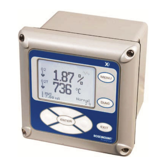
- Page 1 Reference Manual 00809-0100-4889, Rev AB October 2022 ™ Rosemount Advanced Electronics for Zirconium Oxide Flue Gas O Probes...
- Page 2 Essential instructions Read this page before proceeding! Emerson designs, manufactures, and tests its products to meet many national and international standards. Because these instruments are sophisticated technical products, you must properly install, use, and maintain them to ensure they continue to operate within their normal specifications.
- Page 3 Overview The Rosemount Xi is specifically designed to control a zirconium oxide probe for measuring oxygen, usually the O remaining from a combustion process. Call Emerson's Rosemount Customer Central to get recommendations for other oxygen probes: 800 999 9307 (US and Canada).
- Page 4 Equipment supplied by Emerson but not manufactured by it will be subject to the same warranty as is extended to Emerson by the original manufacturer.
-
Page 5: Table Of Contents
Configure.........................27 3.1 Verify installation........................27 3.2 Set test gas values........................29 3.3 Alarm relay output configuration....................29 3.4 Autocalibration setup........................ 30 3.5 Optional advanced features inside the Rosemount Xi..............31 Chapter 4 Startup and operation....................33 4.1 Overview........................... 33 4.2 Startup............................33 4.3 System parameter descriptions....................38 4.4 Probe parameter descriptions....................41... - Page 6 Contents Reference Manual October 2022 00809-0100-4889 Chapter 7 Replacement parts....................75 7.1 Rosemount Xi electronics......................75 7.2 Calibration components......................76 Chapter 8 Optional accessories....................77 8.1 HART handheld Field Communicator..................77 8.2 Asset Management Solutions (AMS)..................78 8.3 By-Pass Packages........................78 ™...
-
Page 7: Description And Specifications
1-1) at the end of this section to compare your order number against your unit. The first part of the matrix defines the model. The last part defines your options and features. Ensure the features and options specified by your order number are on or included with the unit. Emerson.com/Rosemount... -
Page 8: System Overview
E. Reference Air Set (not used if SPS 4001B is used) F. Field Communicator package (optional) G. Optional SPS 400 1B Single Probe Autocalibration Sequencer H. Rosemount Xi Advanced Electronics System overview 1.2.1 Scope This Reference Manual supplies details needed to install, start up, operate, and maintain the Rosemount . - Page 9 Rosemount Xi electronics, Figure 1-2, which does all heater control and signal conditioning in addition to its display/keypad functions. The Rosemount Xi Advanced Electronics is offered to support direct replacement probes with either 120 volt or 44 volt heaters.
- Page 10 Programming reference provides advanced accuracy when measuring at or near level (20.95% O 2. Using the HART interface, the Rosemount Xi's 4-20 mA output line transmits an analog signal proportional to the oxygen level. The HART output is superimposed on the 4-20 mA output line. This information can be accessed through the following: •...
- Page 11 Figure 1-4: Wireless THUM Adapter Optional OxyBalance display and averaging system Receives up to eight 4-20 mA signals from individual Rosemount Xi units. Trends individual outputs and calculates four programmable averages as additional 4-20 mA outputs. OxyBalance graphic displays are shown in Figure 1-5.
-
Page 12: Specifications
Lowest detectable limit 0.01% O Signal stability ±0.03% O Accuracy in reducing conditions ±10% of reading or 0.1% O Ambient temperature effect on Rosemount Xi 4-20 mA Less than 0.0025% O per degree Celsius signal Environmental specifications Rosemount Xi Advanced Electronics... - Page 13 Reference Manual Description and specifications 00809-0100-4889 October 2022 Table 1-2: Product matrix, Rosemount Xi advanced electronics Rosemount Xi Advanced Electronics Code Remote type Single channel Dual channel Single channel traditional architecture for 120 V probes Single channel traditional architecture for 44 V probes...
- Page 14 Description and specifications Reference Manual October 2022 00809-0100-4889 Note All static performance characteristics are with operating variables constant. Specifications subject to change without notice. Rosemount Xi...
-
Page 15: Chapter 2 Install
Do not install the Rosemount in hazardous areas or in the vicinity of flammable liquids. WARNING ELECTRICAL HAZARD If external loop power is used, the power supply must be a safety extra low voltage (SELV) type. Note Plug all unused ports on the probe housing and enclosure with a suitable filling. Emerson.com/Rosemount... -
Page 16: System Considerations
Install Reference Manual October 2022 00809-0100-4889 System considerations A typical system installation for a Rosemount Xi or O probe is shown in Figure 2-1. Figure 2-1: Typical system installation A. Gases B. Duct C. Adapter plate and flange D. Instrument air supply (reference air) E. - Page 17 Consider the temperature limitations of the Rosemount Xi (see Specifications) when selecting the mounting location. 3. Mount the Rosemount Xi at a height convenient for viewing and operating the interface. Approximately 5 ft (1.5 m) is recommended. 4. The keypad window on the Rosemount Xi may have interior and exterior protective membranes.
- Page 18 Install Reference Manual October 2022 00809-0100-4889 Figure 2-2: Rosemount Xi Advanced Electronics - panel mounting details – front and side view A. Maximum Panel Thickness 0.375 (9.75) B. Front View C. Panel Mount Gasket D. 4x Mounting Brackets and Screws provided E.
- Page 19 Note The front panel is hinged at the bottom. The panel swings down for easy access to the wiring locations. Figure 2-4: Rosemount Xi Advanced Electronics - wall/surface mounting – front and side view A. Front View B. 4K Cover Screw C.
-
Page 20: Electrical Installation
Disconnect and lock out power before connecting the power supply. Failure to lock out power could result in serious injury or death. WARNING ELECTRIC SHOCK Install all protective covers and safety ground leads after installation. Failure to install covers and ground leads could result in serious injury or death. Rosemount Xi... - Page 21 Line, voltage, signal, and relay wiring must be rated for at least 221 °F (105 °C). NOTICE If a metal conduit is used with the Rosemount Xi, the conduit should be reliably bonded to protective earth. The grounding plate inside the Rosemount Xi is not bounded to PE and does not provide adequate grounding.
- Page 22 Install Reference Manual October 2022 00809-0100-4889 Figure 2-6: Signal connections at I/O board: outer box A. Shield Termination B. Rosemount Xi Enclosure Rosemount Xi...
- Page 23 A. To Alarm 1 Indicator B. To Heater Relay or Alarm 2 Indicator C. Flame Status input D. To SPS E. To Filed Communicator F. Rosemount Xi Output to Ammeter (4-20mA Check G. Probe Output to Voltmeter (24 VDC Loop) Emerson.com/Rosemount...
- Page 24 B. To Heater Relay or Alarm 2 Indicator 4. Terminate the shield of the 4-20 mA signal wires at the designated ground terminal of the Rosemount Xi. Do not allow bare shield wires to contact the circuit boards. Insulate the shield wires prior to termination.
- Page 25 1. Run the 7-conductor cable between the traditional architecture probe and the installation site for the Rosemount Xi. Use new cable conduit or trough as needed. 2. Install the cable and lead wires to the probe per manufacturer's instructions.
- Page 26 Reference Manual October 2022 00809-0100-4889 3. Install the cable at the probe housing and at the Rosemount Xi enclosure according to the following procedure: a) Unscrew the locking nut from the gland assembly and slide the locking nut back along the cable.
-
Page 27: Chapter 3 Configure
The setting of switch SW4 and the configuration of jumpers JP1 through JP8 must be verified on the I/O board in the Rosemount Xi. All four dip switches on switch SW4 must be set to the Off position, as shown. - Page 28 Extra alarm output Loop power for 4-20 Powered from the Pins 1 and 2 mA/HART Signal from Rosemount Xi the Rosemount Xi to (most common Probe method) Powered from external Pins 2 and 3 DC supply Loop power for 4-20...
-
Page 29: Set Test Gas Values
Use a Field Communicator or the Rosemount Xi to set test gas values for calibration. A Rosemount Xi shipped from the factory has test gas values for low and high set to 0.4% and 8% respectively. This same process must be performed any time a replacement transmitter board, I/O board, or DR board is installed. -
Page 30: Autocalibration Setup
5. Press the Right arrow key to change the state from NO to YES. Autocalibration setup If autocalibration is desired, the Rosemount Xi must be used with an SPS 4001B. The Rosemount Xi must be properly configured before autocalibration can take place. Refer to the applicable SPS 4001B instruction manual for details on performing autocalibration. -
Page 31: Optional Advanced Features Inside The Rosemount Xi
Optional advanced features inside the Rosemount Xi Advanced features available inside the Rosemount Xi are typically ordered as part of the initial package. However, these advanced features are also available for field retrofit. A Rosemount Xi is shipped from the factory with the optional enhanced software features enabled based on the configuration. - Page 32 The stoichiometer feature requires purchasing the acid resistant stoichiometer cell and the stoichiometer feature inside the Rosemount Xi. NOTICE Make sure the DCS is configured for the same range as the Rosemount Xi. For instance: -1% O to 10% O 3.5.3...
-
Page 33: Startup And Operation
October 2022 Startup and operation Overview Interface to the Rosemount Xi for setup, calibration, and diagnostics can be via a Field Communicator or Asset Management System. Setup, calibration, and diagnostic operations differ depending on the selected interface for communications with the transmitter. - Page 34 4.2.3 Rosemount Xi Controls The Rosemount Xi can be used to change the software and alarm settings, to adjust the high and low gas settings, and to initiate the calibration sequence. Refer to the following control descriptions. Use the control keys on the front panel of the Rosemount Xi...
- Page 35 Reference Manual Startup and operation 00809-0100-4889 October 2022 Figure 4-2: Xi menu Emerson.com/Rosemount...
- Page 36 Startup and operation Reference Manual October 2022 00809-0100-4889 Rosemount Xi...
- Page 37 Beginning with Rosemount Xi system software version 1.05 or higher, the main display and diagnostic screens of the Rosemount Xi can be viewed at any time, but further access and unauthorized configuration changes can be prevented by enabling a password protection feature.
-
Page 38: System Parameter Descriptions
System Main Menu > Log Off. The Log Off selection performs on function if the password feature is disabled. The Rosemount Xi has a Reset function that reestablishes all factory default conditions, including the password protection feature, i.e., the password protection falls back to a disabled condition after a reset. - Page 39 Main display, line 3 right hand side data 0 displays PV (O 1 displays SV (O temp) 2 displays TV (cell imp) 3 displays 4 V (cell mV) 4 displays CJC temp 5 displays AO 6 displays OP mode 7 displays Tag Emerson.com/Rosemount...
- Page 40 3 displays 4 V (cell mV) 4 displays CJC temp 5 displays AO 6 displays OP mode 7 displays Tag Revert time Rosemount Xi display reverts to main display time. Also locks screen if password protection is enabled. Language 0 displays English 1 displays Spanish...
-
Page 41: Probe Parameter Descriptions
Heater ramp rate calculated in degree C per second. Flame Stat In Flame input state. (OFF/ON) SPS In SPS input state. (OFF/ON) SPS Out SPS output state. (OFF/ON) Alarm Relay 1 Out Alarm Relay 1 output state. Alarm Relay 2 Out Alarm Relay 2 output state. (OFF/ON) Emerson.com/Rosemount... - Page 42 Failed Const Failed calibration constant. Cal Result Calibration result. Delta Imp Delta impedance since last calibration. Cal Step This represents the step the calibration cycle is in. Time remain seconds Time remaining in the present calibration cycle state. Rosemount Xi...
- Page 43 No = Set to manual calibration mode. Yes = Set to automatic calibration mode. Cal Gas 1 Test gas 1 value. This is the actual value of the gas being applied during the test gas 1 phase of a calibration. Emerson.com/Rosemount...
-
Page 44: Operation Via Hart/Ams
4-20 mA signal, as no net energy is added to the loop. 4.5.1 Field communicator signal line connections When working at the Rosemount Xi, the Field Communicator can be connected directly to test points TP21 and TP22 on the Rosemount Xi I/O board as shown in Figure 4-3. -
Page 45: Offline And Online Operations
Reference Manual Startup and operation 00809-0100-4889 October 2022 Figure 4-3: Field Communicator connection at the Rosemount Xi A. Rosemount Xi I/O Board B. To Field Communicator C. 4-20 mA Signal Monitor (Customer Supplied) D. 4-20 mA Signal Line E. Control Room/AMS or Data Acquisition System F. -
Page 46: Calibration - General
The O probe(s) can be calibrated manually through the handheld Field Communicator or the Rosemount Xi. Fully automatic calibration can be performed automatically using the Rosemount Xi and the SPS 4001B Single Probe Autocalibration Sequencer. calibration This section covers manual calibration. - Page 47 For systems with configuration 1, shown in Figure 4-4, use the following procedure to perform a calibration using the Rosemount Xi. If necessary, use the Rosemount Xi menu tree in for reference. NOTICE To select a menu item, use the up and down arrow keys to scroll to the menu item and press the right arrow key to select the menu item.
-
Page 48: D/A Trim
In the first Start Cal screen, a "Loop should be removed from automatic control" warning appears. 6. Remove the Rosemount Xi from any automatic control loops to avoid a potentially dangerous operating condition and press OK. 7. Follow the Rosemount Xi display prompts to perform the O cal procedure. - Page 49 Figure 4-5, use the handheld Field Communicator to access the D/A trim procedure according to the instructions that follow. Refer to the Field Communicator Rosemount Xi menu tree in Figure 4-2. 1. From the DEVICE SETUP screen, select menu item 2, DIAG/SERVICE, to access the diagnostics and service menu options.
- Page 50 Startup and operation Reference Manual October 2022 00809-0100-4889 Rosemount Xi...
-
Page 51: Chapter 5 Troubleshoot
Figure 5-1. Note that the raw cell millivolt value increases logarithmically as the O concentration decreases. Figure 5-1: O sensor mV reading vs %O at 1357 °F (736 °C) (Reference air, 20.95% O EMF (mV) 7.25 16.1 18.4 21.1 Emerson.com/Rosemount... -
Page 52: General
5.2.2 Electrical noise The Rosemount Xi has been designed to operate in the type of environment normally found in a boiler room or control room. Noise suppression circuits are employed on all field terminations and main inputs. When fault finding, evaluate the electrical noise being generated in the immediate circuitry of a faulty system. -
Page 53: Alarm Indications
To ensure correct operation, you should make sure that the Digital Control System is configured to interpret these signal levels correctly. Once an alarm condition is identified, the Rosemount Xi offers a number of diagnostics to interprest the specific alarm. -
Page 54: Identifying And Correcting Fault Indications
Board Temp The transmitter electronic board reading is Failed High above 259 °F (126 °C) or the Rosemount Xi unit I/O board temperature reading is above 187 °F (86 °C). O2 Htr Ramp The O... -
Page 55: Calibration Passes, But Still Reads Incorrectly
Always set the calibration flow rate when a new diffuser is installed and never readjust this Emerson.com/Rosemount... - Page 56 2. The sensing cell is fastened to the end of the probe tube and uses a corrugated washer to separate the process gases from the ambient reference air. The corrugated washer may be damaged by corrosion. Discard used washer. Rosemount Xi...
- Page 57 Adjust the flow rate back up until this mixing is just eliminated. Calibrate at this flow rate. Replace the diffuser at the first opportunity. WARNING ELECTRIC SHOCK Install all protective equipment covers and safety ground leads after troubleshooting. Failure to install covers and ground leads could result in serious injury or death. Emerson.com/Rosemount...
- Page 58 Troubleshoot Reference Manual October 2022 00809-0100-4889 Rosemount Xi...
-
Page 59: Maintenance And Service
Startup and operation. The Rosemount Xi offers a calibration recommended diagnostic that indicates when the probe needs to be calibrated. Combustion processes that have a high level of ash or other particulate content will cause the diffusion element on the end of the probe to plug off. -
Page 60: Calibration
6.3.1 Automatic calibration The Rosemount Xi can be used with the SPS 4001B in order to perform an auto/semi- automatic calibration. Refer to the SPS 4001B Instruction Manual for further details on how to configure and perform an automatic manual calibration. - Page 61 Reference Manual Maintenance and service 00809-0100-4889 October 2022 Figure 6-1: Rosemount Xi components Emerson.com/Rosemount...
- Page 62 Figure 6-2: Xi front panel components 6.5.1 I/O board replacement Use the procedure that follows to replace and set up the I/O board in the Rosemount Xi. WARNING ELECTRIC SHOCK Disconnect and lock out power before working on any electrical components.
- Page 63 If the existing I/O board has been operated with the Stoichiometric enhanced software feature, this feature must be activated in the new board before the Rosemount Xi Electronics is put back into service. Failure to do so will cause a false analog output signal to the DCS.
- Page 64 8. Set switch SW4 to their proper positions using the old I/O board as a guide. 9. Partially slide the new I/O board into the Rosemount Xi enclosure. Ensure the board is correctly aligned within the slots in the enclosure.
- Page 65 Reference Manual Maintenance and service 00809-0100-4889 October 2022 Figure 6-4: Signal connections at I/O board: outer box A. Shield Termination B. Rosemount Xi Enclosure Emerson.com/Rosemount...
- Page 66 A. To Alarm 1 Indicator B. To Heater Relay or Alarm 2 Indicator C. Flame Status input D. To SPS E. To Filed Communicator F. Rosemount Xi Output to Ammeter (4-20mA Check G. Probe Output to Voltmeter (24 VDC Loop) Rosemount Xi...
- Page 67 12. Connect the ribbon cable to the I/O board. A new cable is supplied and should be used if the old one is damaged. 13. Swing the Rosemount Xi cover up in place and tighten the four screws. 14. Prior to operating the O probe and the Rosemount Xi, all optional software enhancements (previously enabled or not) must be enabled.
- Page 68 6.5.2 Power supply board replacement Use the procedure that follows to replace the power supply board in the Rosemount Xi. Use this procedure to replace an original linear power supply board or the current configuration switching power supply board.
- Page 69 6-1). A new bracket and mounting screws are provided in the replacement kit. 8. Slide the power supply board into the mating slots in the Rosemount Xi enclosure. Make sure the board is correctly aligned in the slots. 9. Install and tighten the bracket mounting screws.
- Page 70 6.5.3 Rosemount Xi front panel replacement Use the procedure that follows to replace the front panel on the Rosemount Xi. Replacement kits with and without the CPU board are available. Use the instructions that apply to the replacement kit you have.
- Page 71 One new cable is supplied in the replacement kit and should be used if either of the ribbon cables are damaged. 5. Remove the wire hinge from the right side of the Rosemount Xi cover. A paper clip or similar device can be inserted into the hole on the left side of the cover to push the hinge out of the cover.
- Page 72 18. If necessary, configure the appearance of the main display. Refer to Configure. 6.5.4 DR board replacement Use the procedure that follows to replace the DR board in the Rosemount Xi that is connected to a direct replacement probe. WARNING ELECTRIC SHOCK Disconnect and lock out power before working on any electrical components.
- Page 73 Reference Manual Maintenance and service 00809-0100-4889 October 2022 Figure 6-8: DR board wiring, right-hand side Emerson.com/Rosemount...
- Page 74 6. Tag and disconnect the wiring to connector J4. 7. Remove the DR board from the Rosemount Xi enclosure. 8. Partially slide the new DR board into the mating slots in the Rosemount Xi enclosure. Make sure the board is correctly aligned in the slots.
-
Page 75: Chapter 7 Replacement Parts
If the existing I/O board has been operated with the Stoichiometric enhanced software feature, this feature must be activated in the new board before the Rosemount Xi is put back into service. Failure to do so will cause a false analog output signal to the DCS. -
Page 76: Calibration Components
Table 7-2: Replacement parts for calibration components Part number Description 1A99119G01 Calibration gas bottles -0.4% and 8% O , balance nitrogen - 550 liters each 1A99119G02 Two flow regulators (for calibration gas bottles) 1A99119G03 Bottle rack Calibration gas bottles cannot be shipped via airfreight. Rosemount Xi... -
Page 77: Chapter 8 Optional Accessories
4-20 mA signal wires. By attaching the Field Communicator at a termination point along the 4-20 mA signal line, you can diagnose problems and configure and calibrate the Rosemount Xi as if you were standing in front of the instrument. For more information, call Rosemount at 1-800-999-9307. -
Page 78: Asset Management Solutions (Ams)
Inconel steel tubes provide effective resistance to corrosion, and the package uses no moving parts, air pumps, or other components common to other sampling systems. For more information, call Rosemount at 1-800-999-9307. Figure 8-2: By-Pass Packages Rosemount Xi... -
Page 79: Rosemount ™ Sps 4001B Single Probe Autocalibration Sequencer
Rosemount SPS 4001B Single Probe Autocalibration Sequencer Emerson specifically designed the Rosemount SPS 4001B Single Probe Autocalibration Sequencer to perform automatic or on-demand calculations. The Rosemount SPS 4001B is fully enclosed in a NEMA cabinet suitable for wall-mounting. This cabinet provides added protection against dust and minor impacts. -
Page 80: O 2 Calibration Gas
Optional accessories Reference Manual October 2022 00809-0100-4889 calibration gas Emerson has carefully designed the O calibration gas and service kits to provide a more ™ convenient and fully portable means of testing, calibrating, and servicing Rosemount oxygen analyzers. Figure 8-3: Calibration Gas Bottles These lightweight, disposable gas cylinders eliminate the need to rent gas bottles. -
Page 81: Appendix A Service Support
™ Rosemount representative. ™ Within the United States, call the Emerson Instrument and Valves Response Center using the 1-800-654-RSMT (7768) toll-free number. This center, available 24 hours a day, will assist you with any needed information or materials. The center will ask for product model and serial numbers and will provide a Return of Material Authorization (RMA) number. - Page 82 © 2022 Micro Motion, Inc. All rights reserved. The Emerson logo is a trademark and service mark of Emerson Electric Co. Micro Motion, ELITE, ProLink, MVD and MVD Direct Connect marks are marks of one of the Emerson Automation Solutions family of companies.
Need help?
Do you have a question about the Rosemount Xi and is the answer not in the manual?
Questions and answers