Table of Contents
Advertisement
Quick Links
One Technology Way • P.O. Box 9106 • Norwood, MA 02062-9106, U.S.A. • Tel: 781.329.4700 • Fax: 781.461.3113 • www.analog.com
Evaluating the
ADPA1107
FEATURES
2-layer Rogers 4350B evaluation board with heat spreader
End launch 2.92 mm (K) jack RF connectors
Through calibration path
Drain or gate pulsing capability
EVALUATION KIT CONTENTS
ADPA1107-EVALZ evaluation board
30 V drain pulser board
EQUIPMENT NEEDED
Pulse generator
Oscilloscope
28 V, 3 A power supply
−4 V power supply
Tektronix TCPA312A current probe
Tektronix TCPA300 current probe amplifier
RF signal generator
Directional coupler
RF power sensor
RF power meter
RF attenuator
DOCUMENTS NEEDED
ADPA1107 data sheet
PLEASE SEE THE LAST PAGE FOR AN IMPORTANT
WARNING AND LEGAL TERMS AND CONDITIONS.
45 dBm (35 W), GaN Power Amplifier, 4.8 GHz to 6.0 GHz
Rev. 0 | Page 1 of 14
ADPA1107-EVALZ
GENERAL DESCRIPTION
The ADPA1107-EVALZ consists of a 2-layer printed circuit
board (PCB) fabricated from a 10 mil thick, Rogers 4350B
copper clad mounted to an aluminum heat spreader. The heat
spreader assists in providing thermal relief to the device as well
as mechanical support to the PCB. Mounting holes on the heat
spreader allow the spreader to be attached to a heat sink.
Alternatively, the spreader can be clamped to a hot and cold
plate. The RFIN and RFOUT ports on the ADPA1107-EVALZ
are populated by 2.92 mm (K) female coaxial connectors, and
the respective RF traces have a 50 Ω characteristic impedance. The
ADPA1107-EVALZ is populated with components suitable for
use over the entire operating temperature range of the device. To
calibrate board trace losses, a through calibration path is
provided between the J6 and J5 connectors. J6 and J5 must be
populated with 2.92 mm (K) female coaxial connectors to use
the through calibration path.
The ground, power, gate control, and detector output voltage
are provided through two test points (TP1 and TP2) and two
24-pin headers (J3 and J4) on the ADPA1107-EVALZ. The
pinouts for these four headers are detailed in Table 1.
RF traces on the ADPA1107-EVALZ are 50 Ω, grounded, coplanar
waveguide. The package ground leads and the exposed pad
connect directly to the ground plane. Multiple vias connect the
top and bottom ground planes with particular focus on the area
directly beneath the ground pad to provide adequate electrical
conduction and thermal conduction to the heat spreader.
The ADPA1107-EVALZ ships with a drain pulsing board
(pulser board) that can be plugged into the ADPA1107-EVALZ
headers and configured to control the biasing of the ADPA1107
by providing a negative gate voltage and a control signal that
connects and disconnects the drain voltage to the ADPA1107-
EVALZ. The ADPA1107-EVALZ can also operate alone in gate
pulsed mode where a negative pulse is applied to the VGG1 pin
of the ADPA1107.
For full details on the ADPA1107, see the ADPA1107 data
sheet, which must be consulted in conjunction with this user
guide when using the ADPA1107-EVALZ.
User Guide
UG-1962
Advertisement
Table of Contents

Related Manuals for Analog Devices ADPA1107-EVALZ


Summary of Contents for Analog Devices ADPA1107-EVALZ
-
Page 1: Features
RF attenuator pinouts for these four headers are detailed in Table 1. DOCUMENTS NEEDED RF traces on the ADPA1107-EVALZ are 50 Ω, grounded, coplanar ADPA1107 data sheet waveguide. The package ground leads and the exposed pad connect directly to the ground plane. Multiple vias connect the... -
Page 2: Table Of Contents
Bill of Materials ................14 Insertion Loss of the Through Calibration Path ......5 Operating the ADPA1107-EVALZ with a Pulsed Gate Voltage . 6 Setup ....................6 REVISION HISTORY 6/2021—Revision 0: Initial Version Rev. 0 | Page 2 of 14... -
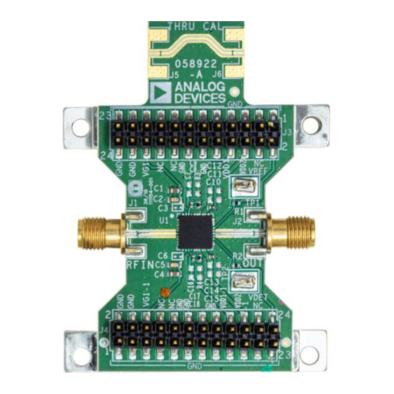
Page 3: Evaluation Board Photographs
ADPA1107-EVALZ User Guide UG-1962 EVALUATION BOARD PHOTOGRAPHS Figure 1. ADPA1107-EVALZ Evaluation Board, Primary Side Figure 2. ADPA1107-EVALZ Evaluation Board, Secondary Side Rev. 0 | Page 3 of 14... -
Page 4: Header Pinout
The schematic for the ADPA1107-EVALZ is shown in Figure 6. The ADPA1107-EVALZ contains four headers, TP1, TP2, J3, and J4. Table 1 describes the pinout of these headers. Table 1. TP1, TP2 J3, and J4 Header Connections on the ADPA1107-EVALZ Header Header Pin Number... -
Page 5: Insertion Loss Of The Through Calibration Path
ADPA1107-EVALZ User Guide UG-1962 INSERTION LOSS OF THE THROUGH CALIBRATION PATH To calibrate board trace losses, a through calibration path is Table 2. Insertion Loss of Through Calibration Path provided between the J6 and J5 connectors. J6 and J5 must be... -
Page 6: Operating The Adpa1107-Evalz With A Pulsed Gate Voltage
Increase the pulse to VGG1 to 0 V. All power supply, ground, and control signals are applied to the J3 and J4 headers of the ADPA1107-EVALZ. For this mode of operation, pulse the gate voltage between −4 V (off) and approximately −2.6 V (on) to set the quiescent current (I... -
Page 7: Operating The Adpa1107-Evalz With The Drain Bias Pulser Board
UG-1962 OPERATING THE ADPA1107-EVALZ WITH THE DRAIN BIAS PULSER BOARD The ADPA1107-EVALZ ships with a drain bias pulser board. A on and off, and the MIC5021YN is a high-side, MOSFET, static block diagram of the pulser board is shown in Figure 4. The pulser switch driver that controls the IRFZ48NSTRLPBF MOSFET. - Page 8 10µF 0.1µF MIC5021YN VBOOST IRFZ48NSTRLPBF INPUT GATE SENSE– PULSE SENSE+ 4700pF PULSED_VDD 1kΩ MBRB2535CTLT4G VDETBIAS VDET VDET VDET_BIAS PULSED_VDD VREFBIAS PULSED_VDD 5015 VREF_BIAS VREF VREF Figure 4. Analog Devices, Inc., Pulser Board Schematic Rev. 0 | Page 8 of 14...
-
Page 9: Setup
ADPA1107- Approximations section. EVALZ so that the P1 header connector of the pulser board connects to the J3 header of the ADPA1107-EVALZ, and the OPERATION pulser board P2 header connects to the J4 header of the Take the following steps to power-up (unless otherwise stated, ADPA1107-EVALZ. - Page 10 UG-1962 ADPA1107-EVALZ User Guide DC SUPPLY DC SUPPLY +28V/3A 0V TO –4V GND PULSE GENERATOR SYNC OUT PULSE OUT VDD AND IDD MONITORING OSCILLOSCOPE CH 1 CH 2 CH 3 TRIGGER TEKTRONIX TCPA300 TEKTRONIX TCPA312A AMPLIFIER CURRENT PROBE OUTPUT INPUT...
-
Page 11: Making Average To Pulsed Approximations
ADPA1107-EVALZ User Guide UG-1962 MAKING AVERAGE TO PULSED APPROXIMATIONS Instruments that can be triggered are required to measure the RF To ensure that partial periods do not contribute significant power, drain current, and power added efficiency (PAE) accurately errors to the measurements, perform averaging over a large under pulsed operation. -
Page 12: Evaluation Board Schematic And Artwork
AGND AGND TSM-112-01-L-DV TSM-112-01-L-DV AGND AGND VDD1-1 VG1-1 1000pF 1µF 2200pF 2200pF 1µF 100pF THU CAL AGND AGND AGND AGND AGND 2.55Ω 25-146-1000-92 25-146-1000-92 AGND AGND AGND Figure 6. ADPA1107-EVALZ Evaluation Board Schematic Rev. 0 | Page 12 of 14... - Page 13 ADPA1107-EVALZ User Guide UG-1962 Figure 7. ADPA1107-EVALZ Assembly Drawing (J6 and J5 Not Installed) Rev. 0 | Page 13 of 14...
-
Page 14: Ordering Information
By using the evaluation board discussed herein (together with any tools, components documentation or support materials, the “Evaluation Board”), you are agreeing to be bound by the terms and conditions set forth below (“Agreement”) unless you have purchased the Evaluation Board, in which case the Analog Devices Standard Terms and Conditions of Sale shall govern. Do not use the Evaluation Board until you have read and agreed to the Agreement.
Need help?
Do you have a question about the ADPA1107-EVALZ and is the answer not in the manual?
Questions and answers