
Subscribe to Our Youtube Channel
Related Manuals for Avnet AVT9152


Summary of Contents for Avnet AVT9152
- Page 1 AVT9152 Evaluation Board User Manual Date: December 07, 2020 Revision 1.0 Rev 1.0 Dec 2020 The information in this document is subject to change without notice P a g e...
-
Page 2: Table Of Contents
Introduction ............................4 Features ............................... 6 Definitions ............................7 Ordering Information .......................... 8 Hardware layout and configuration ....................8 5.1. AVT9152 EVB mechanical drawing ..................11 5.2. Power Supply ..........................12 5.3. Current Measurements ......................13 5.4. Clock Source ..........................13 Reset Sources .......................... - Page 3 List of Figures Figure 1: AVT9152 EVB ..........................5 Figure 2: AVT9152 EVB hardware block diagram ................9 Figure 3: AVT9152 EVB top view ......................10 Figure 4: AVT9152 EVB mechanical drawing ..................11 Figure 5: AVT9152 LTE-BLE module....................27 Figure 6: Onboard sensors ........................
-
Page 4: Introduction
1. Introduction This evaluation kit (EVK) serves as a carrier board for users to evaluate Avnet’s AVT9152 module. The module consists of a Nordic nRF9160 dual mode LTE-M/NB-IoT modem and Nordic nRF52840 Bluetooth 5.0 SoC. The EVK comes with temperature, humidity, pressure, accelerometer, gyroscope and motion sensors. -
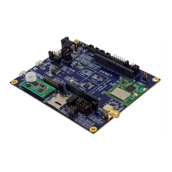
Page 5: Figure 1: Avt9152 Evb
Figure 1: AVT9152 EVB Rev 1.0 Dec 2020 The information in this document is subject to change without notice P a g e... -
Page 6: Features
2. Features AVT9152 Module (Cellular IoT with BLE) Dual mode LTE-M/NB-IoT SoC • 3GPP R13 Cat-M1 & NB1 compliant • 3GPP R14 NB1 & NB2 compliant • Output power: -40dBm to 23 dBm • -108 dBm sensitivity (LTE-M) • -114 dBm sensitivity (CAT-NB1/NB2) •... -
Page 7: Definitions
• Pressure • Temperature • Humidity • Ambient Light • Motion (PIR) Power Input • DC Jack (5V) • Lithium Battery Input (3.6V) 3. Definitions Table 1 below provides the definition of some conventions used in this document. Abbreviation Definition Jxx:n-m ON Jumper fitted Jxx:n-m OFF... -
Page 8: Ordering Information
4. Ordering Information To order the AVT9152 EVB cellular IoT kit please refer to Table 2. Desription AES-CELLIOT-AVT9152KIT AVT9152 cellular IoT evaluation kit Table 2: Ordering Information 5. Hardware layout and configuration The AVT9152 evaluation kit has been designed around the AVT9152 LTE-M/NB with BLE module comprises of the Nordic nRF52840 and nRF9160 RF SoC. -
Page 9: Figure 2: Avt9152 Evb Hardware Block Diagram
Figure 2: AVT9152 EVB hardware block diagram Rev 1.0 Dec 2020 The information in this document is subject to change without notice P a g e... -
Page 10: Figure 3: Avt9152 Evb Top View
Connector nRF52840 serial port Gyroscope Micro SIM AmbiMate eSIM Card Holder Sensor Module Figure 3: AVT9152 EVB top view Rev 1.0 Dec 2020 The information in this document is subject to change without notice P a g e | 10... -
Page 11: Avt9152 Evb Mechanical Drawing
5.1. AVT9152 EVB mechanical drawing 110.00 Figure 4: AVT9152 EVB mechanical drawing Rev 1.0 Dec 2020 The information in this document is subject to change without notice P a g e | 11... -
Page 12: Power Supply
5.2. Power Supply The AVT9152 evaluation kit is designed to be powered in various ways. It is possible to use one of the following different sources: • The wall mount AC-DC universal power adaptor provided together in the kit will supply +5V DC to the evaluation board through the P6 DC power jack. -
Page 13: Current Measurements
+3.6V battery or the external +5V DC power adaptor, respectively. The system power is then delivered to the AVT9152 module and various sensor devices on board such as 3-axis linear accelerometer (LIS2DH12), 3-axis gyroscope (I3G4250D), absolute pressure sensor or barometer (LPS22HB), AmbiMate sensor module (2314277-1), antenna RF switch (F2977) and also the 3.3V and 5V power rails on the Arduino Uno interface. -
Page 14: Reset Sources
P3. The P4 µ.FL connector RF path has been specifically matched to the Taoglas LTE-M flex antenna (FXUB64.18.0150A). The GPS antenna in the AVT9152 evaluation kit is provided through the µ.FL connector J1 located in the AVT9152 module. This J1 connector supports both passive and active type of GPS antenna where +3V is supplied. -
Page 15: Virtual Com Port
5.8. Buttons and LEDs There are only 2 buttons in the AVT9152 evaluation kit, S1 and S2. These are reset buttons for nRF52840 and nRF9160 respectively. The AVT9152 evaluation has 4 LEDs for status indication. The table below here describes them. -
Page 16: Connectors
5.9. Connectors 5.9.1. Arduino UNO Connectors nRF52840 Jumper Arduino Arduino Pin Jumper nRF9160 Pin Setting Connectors Name Setting P0.24 J12:7-8 ON J8:1 J12:8-9 ON P0.24 P1.00 J12:10-11 ON J8:2 J12:11-12 ON P0.25 P0.19 J12:13-14 ON J8:3 D10/SS J12:14-15 ON P0.20 P0.21 J12:16-17 ON J8:4... -
Page 17: Other Connectors
OTA reprogrammable eUICC SIM card as part of the kit accessories. Please refer to the AVT9152 Quick Start Guide for the steps to setup the connection to the backend cloud server. Please note that the eUICC SIM card may not support network connection in certain countries. In this case, user can choose their preferred local network provider and obtain a micro SIM card instead. -
Page 18: Table 11: Sim Interface Jumper
The AVT9152 evaluation kit offers option to select between the embedded SIM, U7 or the micro SIM through jumper J21. Only the embedded SIM MFF2 footprint is provided in the board for user to solder their choice of embedded SIM IC. -
Page 19: Onboard Sensors
There are three MEMS sensors available onboard and another four sensors located in the U5 AmbiMate sensor module (2314277-1) in the evaluation kit. These sensors are controlled through the I2C peripheral bus from either the nRF52840 or nRF9160 device in the AVT9152 module. Jumper J3 allows this selection to be made. -
Page 20: Mems 3-Axis Gyroscope Sensor
J1 connector pin 3 and 4 respectively. User has the flexibility to connect these interrupt pins to either the nRF52840 or nRF9160 devices’ GPIOs in the AVT9152 module using the 6-pin rainbow jumper cable provided with the kit, Arduino UNO connectors and jumper J7, J12, J13. Please refer to the AVT9152 Quick Start Guide for help. -
Page 21: Ambimate Sensor Module
5.10.4. AmbiMate sensor module U5 in the AVT9152 evaluation kit is the AmbiMate sensor module MS4 series from TE Connectivity (2314277-1) that comes with four core sensor solution for motion (PIR), light, temperature and humidity sensing. The AmbiMate module 3.3V power is sourced from U6 LDO powered by VDD_SUPPLY when jumper J2:7-8 is ON. -
Page 22: Description Of The Jumpers
GPIO in the AVT9152 module using the 6-pin rainbow jumper cable provided with the kit, Arduino UNO connectors and jumper J7, J12, J13. Please refer to the AVT9152 Quick Start Guide for help. -
Page 23: Table 15: Description Of The Jumpers
1 to 12 Arduino_D0 to Please refer to Arduino UNO Connectors Arduino_D3 section for details 1 to 12 Arduino_D0 to Please refer to Arduino UNO Connectors Arduino_D3 section for details 1 to 12 Arduino_A2 to Please refer to Arduino UNO Connectors Arduino_A5 section for details nRF91_P0.24_UART_Rx... -
Page 24: Identification
"YY" are the two last digits of the manufacturing year and "WW" identifies the manufacturing week of the year. 7. Known limitations or errors The AVT9152 evaluation board has an error made in the legend printed on the board for jumper J1. The correct reference for the legend is in the below here. J1 legend... -
Page 25: Revision History
8. Revision history Date Version Description December 2020 First release Table 16: Revision History Rev 1.0 Dec 2020 The information in this document is subject to change without notice P a g e | 25... -
Page 26: Appendix - Schematic Diagrams
9. Appendix – Schematic diagrams This section provides design schematics for the AVT9152 EVB. • AVT9152 LTE-BLE module, see Figure 5 • Onboard sensors, see Figure 6 • Debug connectors and reset buttons, see Figure 7 • Arduino UNO interface, see Figure 8 •... -
Page 27: Figure 5: Avt9152 Lte-Ble Module
Figure 5: AVT9152 LTE-BLE module Rev 1.0 Dec 2020 The information in this document is subject to change without notice P a g e | 27... -
Page 28: Figure 6: Onboard Sensors
Figure 6: Onboard sensors Rev 1.0 Dec 2020 The information in this document is subject to change without notice P a g e | 28... -
Page 29: Figure 7: Debug Connectors And Reset Buttons
Figure 7: Debug connectors and reset buttons Rev 1.0 Dec 2020 The information in this document is subject to change without notice P a g e | 29... -
Page 30: Figure 8: Arduino Uno Interface
Figure 8: Arduino UNO interface Rev 1.0 Dec 2020 The information in this document is subject to change without notice P a g e | 30... -
Page 31: Figure 9: Sim Interface
Figure 9: SIM interface Rev 1.0 Dec 2020 The information in this document is subject to change without notice P a g e | 31... -
Page 32: Figure 10: Uart To Usb Converter
Figure 10: UART to USB converter Rev 1.0 Dec 2020 The information in this document is subject to change without notice P a g e | 32... -
Page 33: Figure 11: Lte Rf Switch And Nfc Connector
Figure 11: LTE RF switch and NFC connector Rev 1.0 Dec 2020 The information in this document is subject to change without notice P a g e | 33... -
Page 34: Figure 12: System Power Supply
Figure 12: System power supply Rev 1.0 Dec 2020 The information in this document is subject to change without notice P a g e | 34...
Need help?
Do you have a question about the AVT9152 and is the answer not in the manual?
Questions and answers