Table of Contents
Advertisement
Quick Links
Advertisement
Table of Contents

Related Manuals for Avnet MaaXBoard EM-MC-SBC-IMX8M


Summary of Contents for Avnet MaaXBoard EM-MC-SBC-IMX8M
- Page 1 MaaXBoard (EM-MC-SBC-IMX8M) Hardware User Manual V1.2...
-
Page 2: Copyright Statement
Avnet Manufacturing Services. Avnet Manufacturing Services has the copyright of this document and reserves all rights. Any part of the document should not be modified, distributed or duplicated in any approach and form with the written permission issued by Avnet Manufacturing Services. -
Page 3: Revision History
MaaXBoard HW UserManual V1.2 Revision History Rev. Description Author Date V0.0 Initial version Hugo 20190430 Update description Hugo 20190815 V1.0 V1.1 Update block diagram, picture and Hugo 20191121 description V1.2 Add SRRC description Hugo 20200527 http://www.embest-tech.com... - Page 4 MaaXBoard HW UserManual V1.2 Catalog Revision History ............................3 Chapter 1 Product Overview ........................8 Brief Introduction ........................8 System Block Diagram ......................8 Packing List ..........................9 Product Specifications ......................9 Other Customer Provide Parts ..................... 10 Interface Locations ........................11 Product Dimensions (mm) ....................
- Page 5 MaaXBoard HW UserManual V1.2 2.2.10 Extend Interface J26 ..................... 34 2.2.11 Extend Interface J23 ..................... 36 2.2.12 MIPI-DSI ........................37 Introduction of Peripheral Chips ................... 40 2.3.1 AR8035 ......................... 40 2.3.2 BD71837 ........................40 2.3.3 AW-CM256SM ......................40 Chapter 3 Appendix ..........................
- Page 6 MaaXBoard HW UserManual V1.2 Figure Figure 1.1 MaaXBoard System Block Diagram ..................8 Figure 1.2 MaaXBoard Top View ......................11 Figure 1.3 MaaXBoard Bottom View ....................11 Figure 1.4 Product Dimensions ......................12 Figure 1.5 Height Distribution ......................13 Figure 2.1 USB Type C Slot ....................... 15 Figure 2.2 Button..........................
- Page 7 MaaXBoard HW UserManual V1.2 Table Table 2.1 HDMI Pin Definitions ......................18 Table 2.2 USB Interface Pin Definition ....................20 Table 2.3 Ethernet Interface Pin Definition ..................22 Table 2.4 Camera Connector Pin Definition ..................24 Table 2.5 40 Pin Expansion Pin Header Definition ................27 Table 2.6 Antenna Connector Pin Definition ..................
-
Page 8: Chapter 1 Product Overview
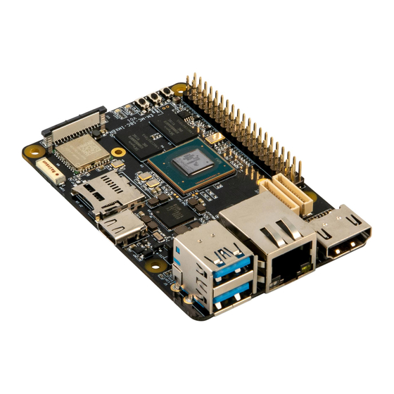
Chapter 1 Product Overview 1.1 Brief Introduction MaaXBoard is a development board for makers, designed by Avnet Manufacturing Services. The MaaXBoard is a single board computer based on NXP IMX8M SOC series, which can be used for the areas such as medical instruments, video surveillance, communications, IOT, makers and so on. -
Page 9: Packing List
MaaXBoard HW UserManual V1.2 1.3 Packing List 1 ×MaaXBoard 1 × Desiccant 1 × Anti-static Bag 1 × Safety Flyer 1 × Quick Start Guide 2 × Electrostatic Foam 1 × Box 1.4 Product Specifications General Specifications: Operating Temperature: 0~70° C (When the CPU loads heavy, need a heatsink) Power Supply: 5V/3A (Power Adapter) Operating Humidity: 20% ~ 90% (non-condensing) Dimensions: 85mm ×... - Page 10 MaaXBoard HW UserManual V1.2 1.5 Other Customer Provide Parts To use the various functions of MaaXBoard, customer should also provide the following parts which are not contained in MaaXBoard Packages. 1 × USB to serial cable (TTL) 1 × 1Gbps Network Cable 1 ×...
- Page 11 MaaXBoard HW UserManual V1.2 1.6 Interface Locations Figure 1.2 MaaXBoard Top View Figure 1.3 MaaXBoard Bottom View http://www.embest-tech.com...
-
Page 12: Product Dimensions (Mm)
MaaXBoard HW UserManual V1.2 1.7 Product Dimensions (mm) Figure 1.4 Product Dimensions http://www.embest-tech.com... - Page 13 MaaXBoard HW UserManual V1.2 1.8 Height Distribution (mm) Figure 1.5 Height Distribution Note: There is tolerance in height due to mechanical treatment. http://www.embest-tech.com...
-
Page 14: Chapter 2 Introduction Of Hardware System
MaaXBoard HW UserManual V1.2 Chapter 2 Introduction of Hardware System This chapter will introduce the structure, expansion and peripheral interfaces of MaaXBoard hardware system in details. 2.1 MaaXBoard Hardware Installation and Start up 2.1.1 Installation Before power up MaaXBoard, you need to connect all necessary peripheral devices, then power on the board. - Page 15 MaaXBoard HW UserManual V1.2 2.2 Details of Interfaces This section will introduce the constructions, principles, interface definitions and considerations of use of MaaXBoard peripherals in detail, so that users may have a deep understanding of the hardware circuitry of the board. 2.2.1 POWER IN MaaXBoard use a USB Type C interface as the +5V power in.
- Page 16 MaaXBoard HW UserManual V1.2 2.2.2 Button There are 3 buttons on the MaaXBoard, S2 as the system power button for the board, S3 and S4 as user button. Figure 2.2 Button http://www.embest-tech.com...
- Page 17 MaaXBoard HW UserManual V1.2 2.2.3 HDMI Powerful video display is an important feature of MaaXBoard. The HDMI 2.0 interface support up to 4096 x 2160 at 60Hz display output. J9 is the interface for connecting an HDMI display device on the MaaXBoard, which is a standard HDMI 19Pin connector.
- Page 18 MaaXBoard HW UserManual V1.2 Table 2.1 HDMI Pin Definitions HDMI(J9) Signal Name Ball Description Signal Type HDMI_TX2+ HDMI data 2 differential positive Differential Data Ground HDMI_TX2- HDMI data 2 differential negative Differential Data HDMI_TX1+ HDMI data 1 differential positive Differential Data Ground HDMI_TX1- HDMI data 1 differential negative...
- Page 19 MaaXBoard HW UserManual V1.2 2.2.4 USB Host MaaXBoard provides a Double-layer USB Host connector (J5), the two USB port are two independent controllers, and each one could provide full speed USB3.0 data communication function, used to extend external devices in USB protocol. Figure 2.4 Double-layer USB Host connector http://www.embest-tech.com...
- Page 20 MaaXBoard HW UserManual V1.2 Table 2.2 USB Interface Pin Definition USB Connector(J5) Signal Name Ball Description Signal Type VBUS1 Power USB1_HOST_DN USB1 PHY USB2.0 differential signal pair negative Differential signal USB1_HOST_DP USB1 PHY USB2.0 differential signal pair positive Ground USB1 PHY USB3.0 received differential signal pair USB1_HOST_RXN negative Differential signal...
- Page 21 MaaXBoard HW UserManual V1.2 USB Connector(J5) Signal Name Ball Description Signal Type Case Earth Case Earth Earth Ground Case Earth 2.2.5 RJ-45 J13 is the physical interface of Gigabit Ethernet, the interface information is shown in the following picture: Figure 2.5 RJ45 Connector http://www.embest-tech.com...
- Page 22 MaaXBoard HW UserManual V1.2 Table 2.3 Ethernet Interface Pin Definition RJ45 Ethernet( J13) Signal Name Ball Description Signal Type MIIA_TRP0 Media-dependent interface 0 positive MIIA_TRN0 Media-dependent interface 0 negative Differential signal MIIA_TRP1 Media-dependent interface 1 positive MiIA_TRN1 Media-dependent interface 1 negative No connection No connection MIIA_TRP2...
- Page 23 MaaXBoard HW UserManual V1.2 2.2.6 Camera J12 on the MaaXBoard is a 30-pin FPC connector that supports MIPI 2Lane Camera input. The following picture shows the information of J12: Figure 2.6 Camera Connector http://www.embest-tech.com...
- Page 24 MaaXBoard HW UserManual V1.2 Table 2.4 Camera Connector Pin Definition Camera(J12) Signal Name Ball Description Signal Type Ground CAM1_DN0 MIPI CSI 1 received differential signal 0 pair negative Differential signal CAM1_DP0 MIPI CSI 1 received differential signal 0 pair positive Ground CAM1_DN1 MIPI CSI 1 received differential signal 1 pair negative...
- Page 25 MaaXBoard HW UserManual V1.2 Camera(J12) Signal Name Ball Description Signal Type No connection No connection No connection No connection No connection No connection No connection http://www.embest-tech.com...
- Page 26 MaaXBoard HW UserManual V1.2 2.2.7 40 Pin Expansion Pin Header J10 on the MaaXBoard is a 40 pin Extend Interface, used to support external devices. The following picture shows the information of the 40 Pin expansion connector J10: Figure 2.7 2.54mm Double Row Pin Header http://www.embest-tech.com...
- Page 27 MaaXBoard HW UserManual V1.2 Figure 2.8 40Pin Pin Header Pin1 Position Table 2.5 40 Pin Expansion Pin Header Definition Expansion(J10) Signal Name Ball Description Signal Type NVCC_3V3 3.3V/500mA output Power 5V_IN 5V power supply input or output Power I2C2_SDA General-purpose input/output 5V_IN 5V power supply input or output Power...
- Page 28 MaaXBoard HW UserManual V1.2 Expansion(J10) Signal Name Ball Description Signal Type GPIO3_IO17 General-purpose input/output SAI2_TXC General-purpose input/output GPIO3_IO08 General-purpose input/output UART5 transmit Data Ground GPIO3_IO09 General-purpose input/output UART2_RXD General-purpose input/output NVCC_3V3 3.3V/500mA output Power UART2_TXD General-purpose input/output ECSPI1_MOSI General-purpose input/output Ground Ground ECSPI1_MISO...
- Page 29 MaaXBoard HW UserManual V1.2 Expansion(J10) Signal Name Ball Description Signal Type SAI2_RXFS General-purpose input/output GPIO1_IO03 General-purpose input/output GPIO3_IO11 General-purpose input/output SAI2_RXD General-purpose input/output Ground Ground SAI2_TXD General-purpose input/output http://www.embest-tech.com...
- Page 30 The Wi-Fi/Bluetooth antennas have two type: onboard ceramic antenna or IPEX antenna. IPEX antenna (customized version) IPEX antenna is empty welding in default, if the customer needs to use this interface, please contact the Avnet Manufacturing Services to customize. IPEX antenna connector’s specification as follows: Figure 2.9 IPEX Antenna Connector Table 2.6 Antenna Connector Pin Definition...
- Page 31 MaaXBoard HW UserManual V1.2 Onboard Ceramic Antenna (Default) Onboard Ceramic Antenna’s specification as follows: Figure 2.10 Onboard Ceramic Antenna http://www.embest-tech.com...
- Page 32 MaaXBoard HW UserManual V1.2 2.2.9 Micro SD Card (TF Card) Micro SD card (TF Card) is used to start the code, the program system curing storage, or provide external storage function. Figure 2.11 Micro SD Card Slot http://www.embest-tech.com...
- Page 33 MaaXBoard HW UserManual V1.2 Table 2.7 Micro SD Card Slot Pin Definition TF card connector(J2) Signal Name Ball Description Signal Type MMC_DAT2 MMC Data bit2 MMC_DAT3 MMC Data bit3 MMC_CMD MMC command 3.3V_VDD 3.3V power supply Power MMC_CLK MMC reference clock Ground MMC_DAT0 MMC Data bit0...
- Page 34 MaaXBoard HW UserManual V1.2 2.2.10 Extend Interface J26 J26 on the MaaXBoard is a 12 pin Wafer connector, used to support GPIO function. The following picture shows the information of the 12 pin Wafer connector J26: Figure 2.12 12Pin Wafer Connector http://www.embest-tech.com...
- Page 35 MaaXBoard HW UserManual V1.2 Table 2.8 12Pin Definition Expansion Interface1 (J26) Description Signal Name Ball Signal Type SAI1_MCLK SAI1 master clock output Ground Ground SAI1_TXD7 SAI1 transmit data bit7 SAI1_TXD6 SAI1 transmit data bit6 SAI1_TXD5 SAI1 transmit data bit5 SAI1_TXD4 SAI1 transmit data bit4 SAI1_TXD3 SAI1 transmit data bit3...
- Page 36 MaaXBoard HW UserManual V1.2 2.2.11 Extend Interface J23 J23 on the MaaXBoard is a 12 pins Wafer connector, used to support GPIO function. The following picture shows the information of the 12 pins Wafer connector J23: Figure 2.13 12Pin Wafer Connector Table 2.9 J23 Pin Definition Expansion Interface1 (J23) Signal Name...
- Page 37 MaaXBoard HW UserManual V1.2 Expansion Interface1 (J23) Signal Name Ball Description Signal Type SAI1_RXC SAI1 receive bit clock 2.2.12 MIPI-DSI J16 on the MaaXBoard is a 30 pin FPC connector that supports MIPI-DSI high-definition and small size screen. The following picture shows the information of 30-pin FPC connector J16: Figure 2.14 30 Pin FPC Connector (MIPI-DSI) http://www.embest-tech.com...
- Page 38 MaaXBoard HW UserManual V1.2 Table 2.10 J16 Pin Definition 30Pin FPC Connector (J16) Signal Name Ball Description Signal Type Ground Ground DSI_DP3 MIPI DSI transmit differential signal 3 pair positive Differential output DSI_DN3 MIPI DSI transmit differential signal 3 pair negative Ground Ground DSI_DP2...
- Page 39 MaaXBoard HW UserManual V1.2 30Pin FPC Connector (J16) Signal Name Ball Description Signal Type No connection No connection Ground Ground No connection VSYS 5V power output VSYS 5V power output Power VSYS 5V power output http://www.embest-tech.com...
- Page 40 MaaXBoard HW UserManual V1.2 2.3 Introduction of Peripheral Chips 2.3.1 AR8035 AR8035 Integrated 10/100/1000 Mbps Ethernet Transceiver. The AR8035 is a single port 10/100/1000 Mbps Tri-speed Ethernet PHY, which provides a low power, low BOM (Bill of Materials) cost solution for comprehensive applications including consumer, enterprise, carrier and home networks, etc.
-
Page 41: Chapter 3 Appendix
MaaXBoard HW UserManual V1.2 Chapter 3 Appendix 3.1 Software MaaXBoard support Linux Yocto system and Android system, for the detail software introduction, please refer to related user manual. Linux MaaXBoard Linux Software Release Note MaaXBoard Linux Software User Manual MaaXBoard Linux Software Development Guide Android MaaXBoard Android Software Release Note MaaXBoard Android Software User Manual... -
Page 42: Chapter 4 Technical Support And Warranty
4.2 Warranty Conditions 12-month free warranty on the PCB under normal conditions of use since the sales of the product; The following conditions are not covered by free services; Avnet Manufacturing Services will charge accordingly: Customers fail to provide valid purchase vouchers or the product identification tag is damaged, unreadable, altered or inconsistent with the products;... - Page 43 Products purchased from unauthorized sales; Warranty (including verbal and written) that is not made by Avnet Manufacturing Services and not included in the scope of our warranty should be fulfilled by the party who committed. Avnet Manufacturing Services has no any responsibility.
-
Page 44: Chapter 5 Contact Information
MaaXBoard HW UserManual V1.2 Chapter 5 Contact Information Tel: +86-755-33190846/33190847/33190848 E-mail: Technical support: support@embest-tech.com Sales contact: chinasales@embest-tech.com Fax: +86-755-25616057 Website: http://www.embest-tech.com/ Address: Tower B 4/F, Shanshui Building, Nanshan Yungu Innovation Industry Park, Liuxian Ave.No.4093,Nanshan District, Shenzhen, Guangdong, China http://www.embest-tech.com...
Need help?
Do you have a question about the MaaXBoard EM-MC-SBC-IMX8M and is the answer not in the manual?
Questions and answers