
Related Manuals for Avnet zedboard


Summary of Contents for Avnet zedboard
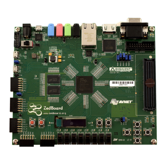
- Page 1 ZedBoard (Zynq™ Evaluation and Development) Configuration and Booting Guide Version 1.1 August 2012...
-
Page 2: Table Of Contents
Hardware Design Block Diagram ..................3 Supplied Files........................4 First Things First ......................... 5 Setting Up the ZedBoard Development Board ............... 5 Extract the Zip File ......................6 PC Setup.......................... 6 Installing the UART Driver and Virtual COM Port ........... 6 ... -
Page 3: Introduction
JTAG configuration mode of the ZedBoard as well as how to boot the processor and configure the programmable logic of the Zynq-7000 device using the SD card and QSPI boot modes. The tasks performed in this guide follow a logical progression such that it is expected that users will start at the beginning and work their way toward the end. -
Page 4: Hardware Design Block Diagram
Hardware Design Block Diagram The hardware platform for this guide is based on the Processor System (PS) configuration and Programmable Logic (PL) bitstream described in the ZedBoard: Zynq-7000 EPP Concepts, Tools, and Techniques hands-on guide found at www.zedboard.org/design. The following figure shows a high-level block diagram of the hardware design. The design requires: ... -
Page 5: Supplied Files
ZedBoard Booting and Configuration Guide ISE Design Suite 14.1 Supplied Files The following directory structure is included with this reference design: boot_image: Empty folder to use to create new BOOT.BIN boot image. demo: Contains the script files, boot image, and application executables: BOOT.BIN: Boot image of First Stage Boot Loader (FSBL), PL bistream, and... -
Page 6: First Things First
ZedBoard Booting and Configuration Guide ISE Design Suite 14.1 First Things First Setting Up the ZedBoard Development Board Refer to the following figure and perform the following steps to set up the board for running the applications. 12V JTAG J20 ... -
Page 7: Extract The Zip File
Figure 3 – Board Connection Setup Installing the UART Driver and Virtual COM Port If the ZedBoard development board has not been connected to the host PC before, it may be necessary to install the software driver for the virtual COM port. The driver... -
Page 8: Jtag Configuration Mode
Application Download 1. Verify the ZedBoard is powered off and that the configuration Mode jumpers are set for JTAG mode (all pins shunted to GND) as in the figure below: 2. - Page 9 ZedBoard Booting and Configuration Guide ISE Design Suite 14.1 5. The FPGA bitstream will be downloaded, followed by the executable file for the software application. Do not close the command window. 6. When the executable has finished loading and is ready to run you should see the...
-
Page 10: Gpio Test Demo
ISE Design Suite 14.1 GPIO Test Demo The GPIO Test application running on the ZedBoard takes user input to select which push-button switch is used to trigger the timer to turn the LED on and off. 1. Follow the screen prompts to select the push button input. One push button is routed to the AXI GPIO peripheral (BTNU) and the other is routed to the CPU GPIO (BTNR) through the EMIO interface between the PS and PL sections. -
Page 11: Sdk Software Tasks
Here we will import the pre-built GPIO test software application that is described in the ZedBoard CTT guide and create the Zynq First Stage Boot Loader (FSBL) that we will copy to the SD card and boot on the ZedBoard. - Page 12 ZedBoard Booting and Configuration Guide ISE Design Suite 14.1 2. Navigate to the <installation>\pa\project_1 folder and select the project_1.ppr project file. Click OK to continue.
- Page 13 ZedBoard Booting and Configuration Guide ISE Design Suite 14.1 3. The project will open and display the Flow Navigator and Project Manager view with the Project Summary. Select File Export Export Hardware… from the PlanAhead GUI. 4. Accept the defaults and check the box to Launch SDK. Click OK to continue.
- Page 14 6. Make note of the base address for the DDR3 SDRAM (ps7_ddr_0 - 0x00100000 and the QSPI Flash (ps7_qspi_0 - ). We will need to know this when 0xE000D000 we program the QSPI Flash later when we prepare to boot the ZedBoard in QSPI boot mode.
-
Page 15: Create The Board Support Package
ZedBoard Booting and Configuration Guide ISE Design Suite 14.1 Create the Board Support Package The first thing we need to create in our empty workspace is a Board Support Package (BSP) on which individual projects can be built. Multiple BSPs and multiple application projects can be held in a single SDK workspace. - Page 16 ZedBoard Booting and Configuration Guide ISE Design Suite 14.1 3. At this point the basic software platform to build general applications for this board has been created. We do not need to add additional software libraries to the BSP or change any settings, so click OK to continue and the software platform will automatically compile link.
-
Page 17: Import The Gpio Test Software Application
ISE Design Suite 14.1 Import the GPIO Test Software Application The GPIO test application is described in the Appendix A of the ZedBoard CTT and is pre-built for us to use here. Feel free to examine and become familiar with the source code for this application. - Page 18 ZedBoard Booting and Configuration Guide ISE Design Suite 14.1 2. Click Browse… and navigate to the <installation>\SDK_sw\gpio_test_0 folder. Check the box to Copy projects into workspace and click Finish to continue. The software application will automatically build and be added to the SDK workspace.
-
Page 19: Running The Gpio Test Software Application
ISE Design Suite 14.1 Running the GPIO Test Software Application 1. Turn off the ZedBoard if it is turned on. Verify the Configuration Mode jumpers are set for JTAG mode (all pins shunted to GND) as in the figure below: 2. - Page 20 ZedBoard Booting and Configuration Guide ISE Design Suite 14.1 4. Since this is a Zynq hardware platform there is no BMM file or ELF file to initialize in Block RAM, so accept the default for the system.bit file for the PL bitstream that was exported from the PlanAhead hardware project earlier.
- Page 21 ZedBoard Booting and Configuration Guide ISE Design Suite 14.1 5. In the Project Explorer window pane select the gpio_test_0 application and right- click to select Run As Run Configurations…...
- Page 22 ZedBoard Booting and Configuration Guide ISE Design Suite 14.1 6. Click on the option in the left panel and press the New to create a new Debug run configuration for the gpio_test_0 software application. 7. Select the new gpio_test_0 Debug run configuration. Click Run continue.
- Page 23 ZedBoard Booting and Configuration Guide ISE Design Suite 14.1 8. You will see the following window warning you that both CPU cores will be reset. Since this system only uses one of the CPU cores it doesn’t matter that both will be reset and we can ignore this warning.
-
Page 24: Create The First Stage Boot Loader
ZedBoard Booting and Configuration Guide ISE Design Suite 14.1 Create the First Stage Boot Loader To prepare for booting the gpio_test_0 software application at power-up later we will need to create the first stage boot loader application. This application is one of the example software applications built into the SDK. -
Page 25: Create The Boot Image
ZedBoard Booting and Configuration Guide ISE Design Suite 14.1 Create the Boot Image To boot the GPIO test application and configure the PL with the hardware bitstream at power on we first need to create the boot image to be copied to our boot media. The boot image is actually the GPIO test and FSBL application executable files and PL bitstream packaged into a single BOOT.BIN file. - Page 26 ZedBoard Booting and Configuration Guide ISE Design Suite 14.1 2. There are a few tasks we need to do while in this window. The PL bitstream and GPIO test application elf file are added in the order they are needed during boot.
-
Page 27: Booting From The Sd Card
With the SDK tasks completed, we are now ready to boot our system from the SD card. Prepare the SD Card 1. Take the SD card that came with the ZedBoard and install it in an open SD card slot on your PC host. Using Windows Explorer identify the drive letter where the SD card is mounted and backup the SD card contents to a folder of your choice on your PC host. -
Page 28: Gpio Test Demo
ZedBoard Booting and Configuration Guide ISE Design Suite 14.1 GPIO Test Demo 1. At power on the Zynq boot ROM samples the boot mode strapping pins and determines the boot method. Once the boot method is determined the boot ROM will search the boot media for the BOOT.BIN file and attempt to execute the First Stage... -
Page 29: Booting From Qspi Flash
JTAG mode (all pins shunted to GND) as in the figure below: 2. Verify the SD card is installed in the ZedBoard. We will be copying the BOOT.BIN file on the SD card into DDR3 memory and then to QSPI Flash. - Page 30 ZedBoard Booting and Configuration Guide ISE Design Suite 14.1 5. The processor will be initialized and the u-boot application will be downloaded for the execution. Do not close the command window. 6. When the u-boot executable has finished loading and is ready to run you should see...
- Page 31 ZedBoard Booting and Configuration Guide ISE Design Suite 14.1 7. Enter the following commands in the serial terminal window to initialize the SD card and QSPI flash: mmcinfo sf probe 0 0 0...
- Page 32 ZedBoard Booting and Configuration Guide ISE Design Suite 14.1 8. Prior to copying the BOOT.BIN file from the SD card to DDR3 memory we need to first write a block of 0xFF to the area of DDR3 that we will use to temporarily store the BOOT.BIN file.
- Page 33 ZedBoard Booting and Configuration Guide ISE Design Suite 14.1 9. This step will copy the BOOT.BIN file from the SD card to DDR3 memory. Recall earlier when we created the SDK workspace that we made note of the QSPI Flash (ps7_qspi_0 - ).
- Page 34 ZedBoard Booting and Configuration Guide ISE Design Suite 14.1 10. Prepare the QSPI Flash. We must erase the area of flash first. The size of the boot image (BOOT.BIN) is bytes, so we will prepare an area slightly larger: 0x40D930...
- Page 35 ZedBoard Booting and Configuration Guide ISE Design Suite 14.1 11. Store the boot image to the QSPI Flash: sf write 0x00200000 0 0x410000 The format of this command is: sf write <source address> <offset> <length>...
- Page 36 ZedBoard Booting and Configuration Guide ISE Design Suite 14.1 12. Turn off the ZedBoard. Verify the Configuration Mode jumpers are set for QSPI boot mode as described and in the figure below: MODE3 (JP10) shunted to 3.3V All other MODE pins shunted to GND 13.
-
Page 37: Gpio Test Demo
ZedBoard Booting and Configuration Guide ISE Design Suite 14.1 GPIO Test Demo 1. At power on the Zynq boot ROM samples the boot mode strapping pins and determines the boot method. Once the boot method is determined the boot ROM will search the boot media for the BOOT.BIN file and attempt to execute the First Stage... -
Page 38: Where To Get More Information
ZedBoard Booting and Configuration Guide ISE Design Suite 14.1 Where to Get More Information ZedBoard Website Documentation, Tutorials, and Reference Designs www.zedboard.org ZedBoard Hardware User’s Guide www.zedboard.org/sites/default/files/ZedBoard_HW_UG_v1_3.pdf Cypress USB-to-UART Setup Guide www.zedboard.org/sites/default/files/CY7C64225_Setup_Guide_1_1.pdf Concepts, Tools and Techniques Guide www.zedboard.org/design...
Need help?
Do you have a question about the zedboard and is the answer not in the manual?
Questions and answers