Avnet Ultra96-V2 Getting Started Manual
Hide thumbs
Also See for Ultra96-V2:
- Getting started manual (33 pages) ,
- Hardware user's manual (32 pages) ,
- Manual (15 pages)
Table of Contents
Advertisement
Quick Links
Advertisement
Table of Contents

Related Manuals for Avnet Ultra96-V2


Summary of Contents for Avnet Ultra96-V2
- Page 1 Ultra96-V2 Getting Started Guide Version 2.0 Page 1 Copyright © 2020 Avnet, Inc. AVNET, “Reach Further,” and the Avnet logo are registered trademarks of Avnet, Inc. All other brands are the property of their respective owners. LIT# Ultra96-V2-GSG-v2-0...
- Page 2 Prior Version History Version Date Comment 25 Jun 2019 Initial Ultra96-V2 Getting Started Guide (30 May 2019 image) 01 Oct 2019 Updated based on 17 Sep 2019 image 18 Dec 2020 Update to the 2020.1 out-of-box image (23 Nov 2020 image);...
-
Page 3: Table Of Contents
Connect to Webserver ..................16 Ultra96-V2 GPIO LEDs Example Project ............18 10 Tutorials ......................20 11 Access Ultra96-V2 Linux Terminal over SSH ............. 21 12 Connect to External Wi-Fi ................... 24 13 Reading On-board Telemetry ................27 14 PMIC Version Check and Update ............... 31 14.1... - Page 4 Figure 2 – Ultra96-V2 Block Diagram ................ 10 Figure 3 – Ultra96-V2 Topology ................11 Figure 4 – Ultra96-V2 SW3 Boot Mode Switch Location ........... 12 Figure 5 – Ultra96-V2 with older 3-pin JTAG/UART Pod ........... 13 Figure 6 – Ultra96-V2 with newer 4-pin JTAG/UART Pod ......... 14 Figure 7 –...
- Page 5 Figure 33 – Example datecode for Device 0x13, with Month = 0x10 and Day = 0x3033 Figure 34 – Compare PMIC Config to a File, 0x13 or 0x14 ........34 Figure 35 – Compare PMIC Config to a File, 0x15 ............ 34 Figure 36 –...
-
Page 6: Getting Started With Ultra96-V2
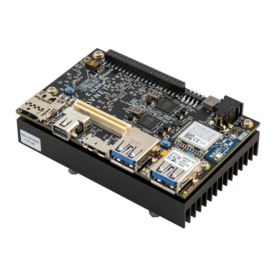
Processor Subsystem (PS) and the Programmable Logic (PL) fabric. Figure 1 – Ultra96-V2 This Getting Started Guide will outline the steps to setup the Ultra96-V2 hardware. It documents the procedure to run a Linux design running on the Quad-core ARM Cortex-A53 MPCore Processing System (PS). -
Page 7: What's Inside The Box
HDMI Monitor o Requires Active miniDP-to-HDMI adapter or cable • USB-to-Ethernet adapter o Ultra96-V2 does NOT have native wired Ethernet, but you can easily add wired Ethernet with inexpensive and readily available adapters http://avnet.me/Ultra96_Accessories for specific part numbers and other suggestions. -
Page 8: What's On The Web
3 What’s on the Web? Ultra96-V2 is a community-oriented kit, with all materials being made available through the http://avnet.me/ultra96-v2 community website. 3.1 Official Documentation: • Getting Started Guide • Hardware User Guide • Schematics • Bill of Materials • Mechanical drawing •... -
Page 9: Ultra96-V2 Key Features
4 Ultra96-V2 Key Features • Linaro 96Boards Consumer Edition compatible • Xilinx Zynq UltraScale+ MPSoC ZU3EG SBVA484 o AES-ULTRA96-V2-G: o AES-ULTRA96-V2-I-G : • Memory o Micron 2 GB (512M x32) LPDDR4 Memory o microSD Socket with microSD card AES-ULTRA96-V2-G: Ships with Delkin Utility MLC 16GB card ... -
Page 10: Figure 2 - Ultra96-V2 Block Diagram
Figure 2 – Ultra96-V2 Block Diagram Page 10... -
Page 11: Ultra96-V2 Basic Setup And Operation
5 Ultra96-V2 Basic Setup and Operation The functionality of the Ultra96-V2 is determined by the application booted from the non-volatile memory – by default the microSD Card. This Getting Started Guide allows system developers to exercise and demonstrate multiple circuits through PetaLinux, including: •... -
Page 12: Example Design
Install TeraTerm or another terminal program of your choice. 2. Set the Ultra96-V2 boot mode switch SW3 to SD Card boot mode as shown below with Switch 1 in the OFF position and Switch 2 in the ON position. Figure 4 – Ultra96-V2 SW3 Boot Mode Switch Location... -
Page 13: Figure 5 - Ultra96-V2 With Older 3-Pin Jtag/Uart Pod
3. If you will be using a USB-to-JTAG/UART Pod for terminal access, plug that into J1 and J3 before plugging in 12V power. Note that the Ultra96-V2 is compatible with Pods that have 3-pin and 7-pin receptacles (align as seen in Figure 5 below), as well as Pods with 4-pin and 8-pin receptacles (as seen in Figure 6 below). -
Page 14: Figure 6 - Ultra96-V2 With Newer 4-Pin Jtag/Uart Pod
ACTIVE mini-DP to HDMI adapter/cable with HDMI Monitor 5. Plug in your 12V Barrel Jack power supply into a wall outlet and then connect the barrel jack to J10 on your Ultra96-V2. Green Vin status LED D17 will light, but the board is not yet powered on. -
Page 15: Figure 7 - Press The Sw4 Power On Button
The Ultra96 USB-to-JTAG/UART Pod ships with pre-programmed firmware that allows the JTAG interface to be recognized by Xilinx Vivado software. Additionally, most host machines will also automatically install the driver for the Serial Terminal interface. 6. If using the JTAG/Pod, do the following: •... -
Page 16: Connect To Webserver
Open network called Ultra96-V2_<MAC_ADDRESS> as shown below. Note that the MAC Address shown will be different than the image below as it will match your specific board’s MAC Address. Figure 8 – Ultra96-V2 As An Available Network 2. Select the Ultra96-V2 Network and Connect. -
Page 17: Figure 9 - Connected To Ultra96-V2 Webserver
3. Once connected, open a browser on the connected machine, and browse to the IP address of the board, which is http://192.168.2.1. The browser page will show like below. Figure 9 – Connected to Ultra96-V2 Webserver Page 17... -
Page 18: Ultra96-V2 Gpio Leds Example Project
The Ultra96-V2 LEDs are D3, D4, D6, and D7, shown below: Figure 10 – Ultra96-V2 User LEDs 1. Next we want to access the Ultra96-V2 GPIO LEDs example project. From the Ultra96- V2 home page select Ultra96-V2 GPIO LEDs example project Figure 11 –... -
Page 19: Figure 12 - Led0/D3 Changed To Steady-State On
2. All LEDs will be at an unknown state to begin with. Select the drop down menus and begin changing the status of the GPIO LEDs. The LED blinking upon boot-up is D3, so consider changing that one first to “On.” Figure 12 –... -
Page 20: Tutorials
Tutorials or back in your browser to go back. 3. Click Using Ultra96-V2. 4. This tutorial goes over the various ways you can interact with the Ultra96-V2. As of now we have interacted using the Webserver and UART on the Pod. -
Page 21: Access Ultra96-V2 Linux Terminal Over Ssh
11 Access Ultra96-V2 Linux Terminal over SSH 1. If connected via UART, click File Disconnect 2. Open TeraTerm and then select File New connection… as seen in the image below. Figure 14 – TeraTerm New Connection Page 21... -
Page 22: Figure 15 - Ssh Terminal Settings
3. A new TeraTerm: New connection window will open. We now want to connect to Ultra96-V2 over SSH, select TCP/IP and then configure your Terminal settings to use the IP address that you discovered previously, similar to the below figure. -
Page 23: Figure 17 - Ssh Authentication
Please type in root for the User name and then type in root for the Passphrase as well. Then select OK. Figure 17 – SSH Authentication 7. You now have access to the Ultra96-V2 Terminal! Figure 18 – Ultra96-V2 Terminal Page 23... -
Page 24: Connect To External Wi-Fi
12 Connect to External Wi-Fi To perform package updates or access anything from the Internet, the board must be connected to an external internet source. 1. Click Configurations and then WiFi Setup. Figure 19 – WiFi Setup 2. Click the Refresh Connections button then click the pull-down for Network Name. Next, select a network available to you. -
Page 25: Figure 21 - Successfully Connected
Figure 22 – Determine IP Address Assigned to Ultra96-V2 5. Connect your host to the same Wi-Fi source. With both your host and Ultra96-V2 board connected to the same Wi-Fi source, point your browser to this new IP address, and you will be back to the same interactive browser page for Ultra96-V2. -
Page 26: Figure 23 - Connected To Ultra96-V2 Via External Wi-Fi
Figure 23 – Connected to Ultra96-V2 Via External Wi-Fi Page 26... -
Page 27: Reading On-Board Telemetry
-l Figure 24 – I2Cdetect This shows all the available I2C busses on the Ultra96-V2. The one corresponding to the PMICs is found based on the hardware connections in the schematic. The signals are called ‘PMIC_SCL’... -
Page 28: Figure 26 - Pmics On I2C-6
2. To see what is specifically on i2c-6, enter i2cdetect -r 6, and then enter ‘Y’ to confirm. The addresses associated with the PMICs are shown below. Figure 26 – PMICs on I2C-6 3. Read the telemetry from the PMICs by entering sensors in your terminal. The output will scroll to the screen, which is copied below in sections. -
Page 29: Figure 28 - Telemetry From Pmic 0X13/43
Figure 28 – Telemetry from PMIC 0x13/43 Figure 29 – Telemetry from MPSoC Sysmon Page 29... -
Page 30: Figure 30 - Telemetry From Pmic 0X14/44
Figure 30 – Telemetry from PMIC 0x14/44 As you can see the current, voltage, and temperature measurements are reported back.. Page 30... -
Page 31: Pmic Version Check And Update
14 PMIC Version Check and Update Another capability that we have is to check the version of the programming inside the PMICs. As described in the Ultra96-V2 PCN19003, there have been multiple releases of the PMIC programming files. This is also described in this blog. - Page 32 6. To see the capabilities of the pmic_prog utility, access the help menu # ./pmic_prog -help Version: 1.0 Usage: pmic_prog [-h] COMMANDS -h = display this help and exit COMMANDS: detect I2C_BUS to detect all the PMICs on an i2c bus with: I2C_BUS the i2c bus number (decimal: 0-255) Example:...
-
Page 33: Figure 32 - Pmics Detected On I2C Bus 6
Next use a basic ‘detect’ command to confirm we see the correct PMICs. 7. Enter the ‘detect’ command on I2C bus 6 # ./pmic_prog detect 6 Figure 32 – PMICs Detected On I2C Bus 6 8. For the Rocky/5401 devices (0x13 and 0x14) a date code is stored at locations 0x2A and 0x2B for each PMIC. -
Page 34: Figure 34 - Compare Pmic Config To A File, 0X13 Or 0X14
9. To perform a comparison against an existing configuration file, use the read-registers command with an input file, as follows. # ./pmic_prog read-registers 6 0x13 -i ./pmic-configs/U96V2_5401_0x13_191030.txt # ./pmic_prog read-registers 6 0x14 -i ./pmic-configs/U96V2_5401_0x14_191030.txt # ./pmic_prog read-registers 6 0x15 -i ./pmic-configs/U96V2_38060_0x15_190301.txt Figure 34 –... -
Page 35: Pmic Reprogramming
14.2 PMIC Reprogramming If you are not using the latest PMIC programming files, then you may find your board does not perform to its maximum potential. The included pmic_prog utility can also reprogram your PMICs. WARNINGS! The Infineon PMICs only have 26 programming locations. Each time the devices are reprogrammed, another location is consumed. - Page 36 5. To reprogram the 0x14 device, enter the following command, making sure that the two highlighted numbers match! # ./pmic_prog program 6 0x14 -i ./pmic-configs/U96V2_5401_0x14_191030.txt 6. Follow the procedure as before. The 0x15 / Manhattan / 38060 device programming has not been updated since the original release of the board.
-
Page 37: Power Off
Figure 38 – Power Down Initiated Through Short Press of SW4 3. Please note, if you do not let your Ultra96-V2 power off as per the power down sequencing requirements (such as unplugging the barrel jack), your microSD Card may get corrupted or damaged. -
Page 38: Getting Help And Support
16 Getting Help and Support 16.1 Avnet Support The Ultra96-V2 is a versatile development kit that allows evaluation of the Zynq MPSoC, which can help you adopt Zynq into your next design. All technical support is offered through http://avnet.me/Ultra96_Forum. Ultra96-V2 users are encouraged to participate in the forums and offer help to others when possible. -
Page 39: Xilinx Support
16.2 Xilinx Support For questions regarding products within the Product Entitlement Account, visit the Contact Support site for Xilinx: https://www.xilinx.com/support/service-portal/contact-support.html For technical support including the installation and use of the product license file, contact Xilinx Online Technical Support at www.xilinx.com/support. The following assistance resources are also available on the website: •... -
Page 40: Installing And Licensing Xilinx Software
17 Installing and Licensing Xilinx Software 17.1 Install Vivado Design Suite, Design Edition The Zynq device on the Ultra96-V2 is supported in Vivado Design Suite, Design Edition. Version 2018.1 or later is required to use the board definition file provided on the Avnet GitHub. -
Page 41: Figure 39 - Voucher Confirmation
5. At the confirmation screen, click Yes. Figure 39 – Voucher Confirmation 6. Under Certificate Based Licenses, find OEM Zynq ZU3 Ultra96 Vivado Design Edition Voucher pack and check the box. Now click Generate Node-Locked License. Figure 40 – Generate Node-Locked Page 41... -
Page 42: Figure 41 - Select Host Information
7. Create or select your Host ID. Click Next. Figure 41 – Select Host Information Page 42... - Page 43 8. Review the license request, then click Next again. If a full seat of Vivado System or Design Edition has already been installed, then no further software will be needed. Please check online for any updates at: www.xilinx.com/support/download/index.htm For detailed instructions on installing and licensing the Xilinx tools, please refer to the latest version of Vivado Design Suite User Guide Release Notes, Installation, and Licensing (UG973).
-
Page 44: Certification Disclaimer
This product shall only be connected to an external power supply that is 96boards compliant. Only compatible plug-in modules shall be connected to Ultra96-V2. The connection of incompatible devices may affect compliance or result in damage to the unit and void the warranty.
Need help?
Do you have a question about the Ultra96-V2 and is the answer not in the manual?
Questions and answers