Table of Contents
Advertisement
Quick Links
Advertisement
Table of Contents

Subscribe to Our Youtube Channel
Related Manuals for Avnet AVT9152 EVB


Summary of Contents for Avnet AVT9152 EVB
- Page 1 AVT9152 EVB Quick Start Guide v1.0 – December 04, 2020 Page 1...
- Page 2 Document Control Document Version: Document Date: 04 Dec 2020 Document Author: Jennifer Sy Document Classification: Public Document Distribution: Public Version History Version Date Comment 04 Dec 2020 First Release Page 2...
-
Page 3: Table Of Contents
Kit content ............................. 4 eUICC ..............................4 AVT9152 EVB demo web portal ......................5 Sign up for an account ........................5 Add AVT9152 EVB to demo web portal ..................6 Dashboard view ..........................8 4.3.1 Latest measurements ......................9 4.3.2 Historical data ........................ -
Page 4: Introduction
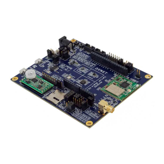
1 Introduction This document provides step-by-step guide to connect AVT9152 EVB to the demo web portal. 2 Kit content An AVT9152 EVB kit includes: 1) AVT9152 evaluation board 2) External paddle LTE antenna 3) Active GPS/GALILEO ceramic patch antenna 4) Global eUICC plastic card... -
Page 5: Avt9152 Evb Demo Web Portal
4 AVT9152 EVB demo web portal This section shows the user how to register to and access AVT9152 EVB unit from AVT9152 demo web portal. 4.1 Sign up for an account Proceed to add AVT9152 EVB to demo web portal if you already have an account with the demo web portal. -
Page 6: Add Avt9152 Evb To Demo Web Portal
5) Use the temporary password provided to login for the first time then replace with own password for subsequent login. 4.2 Add AVT9152 EVB to demo web portal 1) Open https://avtdemo.iotconnect.io/login. 2) Fill in your account login details and click LOGIN. - Page 7 3) Click the Devices icon to switch to Devices view. 4) Click ADD DEVICE. 5) Locate your AVT9152 EVB’s 15-digit IMEI number. Page 7...
-
Page 8: Dashboard View
6) Fill in Device details and click ADD. Your EVB’s IMEI Name to identify the device. For example, avt9152-<IMEI> 7) AVT9152 EVB successfully added. 8) Complete set up AVT9152 EVB to start collecting data. 4.3 Dashboard view Dashboard view presents the latest data from the selected unit as well as the daily average environmental data for the past 7 days. -
Page 9: Latest Measurements
* A green circle on the right of the selected unit’s display name indicates the device is connected while a red circle indicates the device is not connected. ** Rotation speed is calculated from the biggest angular change on the z-axis triggered by rotating clockwise or counterclockwise the AVT9152 EVB in a face up position. Page 9... -
Page 10: Historical Data
4.3.2 Historical data 4.4 Devices view Devices view shows the latest data from the selected device as well as a line chart of the last 20 (max) data points of the selected attribute received from the time this view is loaded. It allows the user to enable/disable the motion (PIR) detection and the GPS location tracking. -
Page 11: Device Latest Information
Select from this column 4.4.1 Device latest information Enable / Disable motion (PIR) detection Enable / Disable location tracking 4.4.2 Live data Connection status Selected attribute Page 11... -
Page 12: Set Up Avt9152 Evb
5 Set up AVT9152 EVB This section provides a step-by-step guide on how to prepare AVT9152 EVB to start sending data to AVT9152 demo web portal for the out-of-box demo. 5.1 Make sure the following jumpers are in place AVT9152 EVB is shipped with jumpers on their default positions described in this section. User may go... -
Page 13: Connect The Following Pins With Jumper Wires
J7 : 5-6 Connects D1 to nRF9160 P0.16 J12 : 2-3 Connects D6 to nRF9160 P0.20 J13 : 2-3 Connects A2 to nRF9160 P0.13 J13 : 5-6 Connects A3 to nRF9160 P0.14 J15 : 3-4 Connects UART_TX to nRF9160 P0.25 for USB-to-UART on P1 J15 : 1-2 Connects UART_RX to nRF9160 P0.24 for USB-to-UART on P1 J21 : 1-2... -
Page 14: Attach Provided Gps And Lte Antenna
5.3 Attach provided GPS and LTE antenna GPS antenna connector, J1 LTE antenna connector, P3 5.4 Insert LTE CAT-M1 or CAT-NB1 SIM card SIM Card slot, J14 Page 14... -
Page 15: Turn On Avt9152 Evb
Connect P1 to your PC with a micro USB cable. This will provide a virtual COM port interface for AVT9152 to send and receive data to and from a terminal program. Virtual COM port driver can be downloaded from https://www.ftdichip.com/Drivers/VCP.htm. AVT9152 EVB ships with pre-programmed demo software (source code available at https://github.com/Avnet/AVT9152_DEMO). Page 15... - Page 16 It sends the application version, modem firmware version and its IMEI number on startup through this virtual COM port at 115200 baud rate, 8 data bits, 1 stop bit, no parity, no flow control. Press S2 to reset AVT9152’s nRF9160 in order to see the startup messages. Application version Modem firmware version 15-digit IMEI number...
Need help?
Do you have a question about the AVT9152 EVB and is the answer not in the manual?
Questions and answers