
Related Manuals for Avnet RZBOARD V2L


Summary of Contents for Avnet RZBOARD V2L
- Page 1 AI-Accelerated RZ/V2L Development Board RZBoard V2L Hardware User Guide v1.0 October 05, 2022 Page 1...
-
Page 2: Document Control
1 Document Control Document Version: Document Date: 10/05/2022 Document Author: Peter Fenn Document Classification: Public Document Distribution: Public 2 Version History Version Date Comment 10/05/2022 Initial public release (Rev 1.2 production PCB) Page 2... -
Page 3: Table Of Contents
RZBoard V2L Block Diagram ............... 12 Renesas parts on RZBoard (8 devices) ..............12 RZBoard V2L Component Locations (Top) ..........13 RZBoard V2L BaseBoard Component Locations (Bottom) ......14 Debug Header, Switches and LEDs ............. 15 6.8.1 Debug UART 4-pin Header (J19)................15 6.8.2... - Page 4 13 Accessories: RZBoard V2L Add-On Options ............38 13.1 MIPI DSI 7-inch Capacitive Touch LCD Display (Optional) ......38 13.2 MIPI CSI 5 MP Camera (Optional) ............... 38 13.3 Other SBCs, SOMs and Accessories from “Avnet Boards” ......39 Page 4...
- Page 5 Figures Figure 1 – RZ/V2L Processor Block Diagram ............10 Figure 2 – RZBoard V2L Block Diagram (Rev 1.2 PCB) ........... 12 Figure 3 – J1 Header pin-numbering ................ 16 Figure 4 – Selecting the Boot Mode ................16 Figure 5 – RZBoard V2L Memory Resources ............18 Figure 6 –...
-
Page 6: Hardware Checklist
Hardware items recommended for application development are the following Item Description Computer (Windows / Linux / Mac) with installed development tools (see below) Avnet RZBoard V2L board USB to Serial Cable (or use of VCOM interface from debugger probe) 1x fly-lead (to select SCIF download boot mode) -
Page 7: Introduction
DRP-AI accelerator plus H.264 video (1920 x 1080) encode/decode function, making it ideal for implementing cost-effective embedded-vision applications. RZBoard V2L is engineered in a compact Raspberry Pi form-factor with a versatile set of expansion interfaces, including Gigabit Ethernet, 801.11ac Wi-Fi and Bluetooth 5, two USB 2.0 hosts and a USB 2.0 OTG interface, MIPI DSI and CSI camera interfaces, CANFD interface, Pi-HAT compatible 40-pin expansion header and Click Shuttle expansion header. -
Page 8: Rzboard V2L Info
RZBoard V2L Hardware User Guide (this document) • RZBoard V2L Linux Yocto User Manual • RZBoard V2L Linux Yocto Development Guide • RZBoard V2L Schematic and BOM (available under NDA) • Renesas RZ/V2L Group User's Manual: Hardware (r01uh0936ej0100-rzv2l.pdf) Typical Hardware Setup (with optional 7-inch panel attached) -
Page 9: Rzboard V2L Architecture & Features
DRP Simple ISP machine-vision library functions (supports up to 1920 x 1080) • H.264 Hardware Video Encode/Decode (1920 x 1080) • 128KB ECC RAM Avnet SBC development board in Raspberry-Pi / MaaXBoard form-factor includes: • 2GB DDR4 (16-bit, single-channel, with in-line ECC) • 16GB eMMC memory •... -
Page 10: Block Diagram - Renesas Rz/V2L Processor
Block Diagram – Renesas RZ/V2L Processor Figure 1 – RZ/V2L Processor Block Diagram DRP-AI Accelerator Core Dynamically Reconfigurable Processor (DRP) is a programmable, highly flexible accelerator core, optimised for use in AI accelerated vision applications DRP-AI Relevant AI Operations Resource Specs. -
Page 11: Rz/V2L Architecture (Acpu Bus, Mcpu Bus, System Bus)
RZ/V2L Architecture (ACPU bus, MCPU bus, System bus) Page 11... -
Page 12: Rzboard V2L Block Diagram
RZBoard V2L Block Diagram Figure 2 – RZBoard V2L Block Diagram (Rev 1.2 PCB) Renesas parts on RZBoard (8 devices) • RZ/V2L Processor • RAA215300 PMIC • 5P35023B Clock • DA7212 Audio Codec • UPD720115 USB Hub • ISL61852 USB Power •... -
Page 13: Rzboard V2L Component Locations (Top)
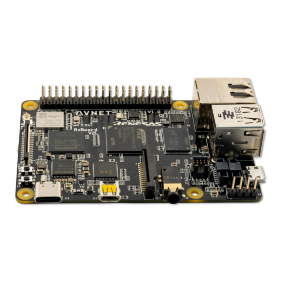
Stacked USB host connectors S2 button switch (USER) OTG USB 2.0 connector USB-C 5V power input MIPI to HDMI display convertor 40-pin Pi-HAT expansion header Micro HDMI display connector Table 3 – Key Components on RZBoard V2L (Top) Page 13... -
Page 14: Rzboard V2L Baseboard Component Locations (Bottom)
/ microSD QSPI bus switch USB 4-port HUB 3V3 / 1V8 Greenpak level-shifter 3V3 / 1V8 level-shifter CAN transceiver USB OTG 5V switch MIPI / HDMI display switch Mounting Holes (standoffs or Pi-Hat) Table 4 – Key Components on RZBoard V2L (Bottom) Page 14... -
Page 15: Debug Header, Switches And Leds
Debug Header, Switches and LEDs 6.8.1 Debug UART 4-pin Header (J19) A USB-Serial debug cable needs to be attached to the J1 header for console debug output and Linux command-line access. RZBoard V2L Serial Interface Signals Signal Direction J19 USB-Serial cable... -
Page 16: Figure 3 - J1 Header Pin-Numbering
BOOT2 is set by use of a flywire from J19-pin1 of Debug UART 4pin header. BOOT2 Strapping to change boot mode Default. No flywire strapping required Strap J19-pin1 to 5V (J1-pin2 on HAT 40pin header) Figure 3 – J1 Header pin-numbering BOOT1 is set by DIP switch SW1.1 BOOT1 Strapping to change boot mode... -
Page 17: Push-Button Switches
6.8.3 Push-Button Switches Two pushbuttons are located near the board edge, in the bottom-left corner Ref. Switch Button Switch RZ/V2L PMIC Name Function GPIO Pin ONOFF Board ON/OFF control PMIC PWRON input USER USER function (unassigned) RZ_P39_0 6.8.4 Status LEDs RZ/V2L Ref. -
Page 18: Memory Resources
QSPI flash QSPI0 16 MB 104 MHz, x4 bus Adesto AT25QL128A-UIUE-T Figure 5 – RZBoard V2L Memory Resources 6.9.1 eMMC Memory (Partition size and Programming) • For convenience, the procedures for changing partition size and programming new images into eMMC flash memory are included in the Appendix area of this User Guide document •... -
Page 19: Peripheral Devices And Interfaces
6.10 Peripheral Devices and Interfaces 6.10.1 J1: Pi-HAT compatible 40-pin header Possible HAT J1 RZBoard V2L Possible HAT J1 RZBoard V2L Pin Function Signal Name Pin Function Signal Name 5V_SYS VDD_3V3 I2C_SDA 5V_SYS RZ_RIIC2_SDA I2C_SCL RZ_RIIC2_SCL GPIO / GPCLK0 UART_TX... -
Page 20: J1: Pinout Comparison With Mikroe Pi-2-Click Hat Adapter
6.10.2 J1: Pinout Comparison with MikroE Pi-2-Click HAT Adapter • Pinout for recommended HAT adapter ($8.00) is shown below (this accommodates two Click boards) Pi-2-Click HAT J1 RZBoard V2L Pi-2-Click HAT J1 RZBoard V2L Pin Function Signal Name Pin Function... -
Page 21: Mikroe Click Boards
6.10.3 MikroE Click Boards • Over 1200+ Click boards available. Orderable from Avnet http://avnet.me/click • Parametric search tool on MikroE website • Open source library code available at https://www.mikroe.com/click-boards 6.10.4 Pi HAT Expansion Boards • Ecosystem of Pi HAT boards support a wide range of functionality •... -
Page 22: J3: Usb 2.0 Otg Interface
In host mode this interface’s USB 5V output is rated for 600mA max. 6.10.7 J6, J20: USB 2.0 Host Interfaces RZ_USB1 controller connects to an onboard USB Hub that supports 4 USB Host interfaces: USB HUB Label on RZBoard V2L HUB_#1 J20 WTB connector USB (expansion interface) HUB_#2 < Unused >... -
Page 23: J20: Usb1 And Ssi3 (10-Pin Wtb Header)
6.10.10 J20: USB1 and SSI3 (10-pin WTB header) • An ESD-protected USB host interface from RZ_USB1 4-port hub is available on J20 • The 4-wire SSI3 (I2S) digital audio interface on J20 pins 6.10.11 J13: HDMI Display Output • The 4-lane MIPI-DSI output from the RZ/V2L processor is routed via NX3DV642 high-speed MIPI switch devices to drive either: a) the J5 MIPI Interface, or b) the J13 HDMI interface (via the U38 MIPI to HDMI convertor) -
Page 24: J5: Mipi-Dsi Display And Touchscreen Interface
6.10.12 J5: MIPI-DSI Display and Touchscreen Interface • A 4-lane MIPI-DSI interface is supported plus touchscreen interface. • This supports the 7-inch MaaXBoard 720 x 1280 display via the 30-pin J5 ribbon connector. • This 30-pin connector has same form-factor as display connector on Raspberry Pi but the pinout is adapted to include an I2C touchscreen controller interface DSI Connector RZ/V2L... -
Page 25: J4: Mipi-Csi Camera Interface
6.10.13 J4: MIPI-CSI Camera Interface The 2-lane, 15-pin MIPI connector pinout is the same as what is used on Raspberry-Pi board Camera RZ/V2L Control I/O Processor I/O CAM1_PWR# RZ_P2_0 CAM1_RST# RZ_P40_2 RZ_RIIC0_SCL RZ_RIIC0_SCL RZ_RIIC0_SDA RZ_RIIC0_SDA 6.10.14 J7: Gigabit Ethernet RJ45 Interface The 10/100 Ethernet subsystem is comprised of: •... -
Page 26: Audio Codec
6.10.15 Audio Codec RZ_SSI0 interface of RZ/V2L (Serial Audio Interface #0) connects to Dialog DA7212-01UM2 stereo audio Codec. PCM audio between Wi-Fi/BT module and the Codec, requires routing through the RZ/V2L processor. RZ_SCI0 (Serial Communications Interface #1) connects the RZ/V2L processor with the Bluetooth PCM audio interface of the WiFi/BT module. -
Page 27: Wireless Connectivity
6.11 Wireless Connectivity RZBoard V2L uses a Murata Type-1ZM Wi-Fi 5 and Bluetooth 5 combo module, which is based on the NXP 88W8987 device. Dual-band 2.4 GHz and 5 GHz Wi-Fi operation is supported Interfaces between the 88W8987 based module and the RZ/V2L host processor include: •... -
Page 28: Bt/Ble Uart Interface
6.11.4 Wi-Fi / BT antenna This board only supports an external antenna, attached via UFL / IPEX MHF connector. The antenna shipped with RZBoard V2L (as used in regulatory certifications) is Molex p/n: 1461870050 6.12 Power Architecture RZBoard is a power-efficient low-wattage board (typical 1.5W ~ 4.5W depending on use case) 6.12.1... -
Page 29: Power Regulation (Raa215300 Pmic: 6 Buck Regulators, 3 Ldos)
6.12.2 Power Regulation (RAA215300 PMIC: 6 Buck Regulators, 3 LDOs) The Renesas PMIC efficiently converts the 5V power input into multiple regulated supply rails Power architecture of RZBoard is based on the Renesas diagram below (See table for detail on RZBoard’s specific usage of the PMIC output rails) PMIC Voltage RZBoard Power Rail... -
Page 30: Power Consumption Measurements
$20 https://www.amazon.com/Tester-Eversame-Voltmeter-Ammeter-Braided/dp/B07MGQZHGM Note: An invalid current measurement will be seen if RZBoard V2L is powered from a USB port of same PC as used by the debugger probe! To achieve a useful current measurement, power RZBoard from a separate power-adapter, or disconnect the debugger probe. -
Page 31: Technical Support
RZBoard Support Forum at http://avnet.me/RZBoard-forum (This forum is monitored by technical resources in Avnet’s Advanced Applications Group) If interested in customization of RZBoard V2L with customer-specific options, send an email inquiry with detail of desired changes (and use-case) to customize@avnet.com... -
Page 32: Cautionary Notes
5) Ambient operating temperature range when using RzBoard V2L shall not exceed: -30C to +85C 11 Disclaimer RZBoard V2L is engineered for use as a development board (to facilitate product evaluation and system- level prototyping) as well as for potential use as a sub-assembly in custom OEM end-products. -
Page 33: Software: Emmc Memory And Device Tree Overlays
Note: Complete steps 1-6 below, prior to running the provided flash_bootloader.bat file: 1) Download the latest image files, .bat and macro files from https://avnet.me/RZBoard_emmc extract the zipped files to a staging folder on the development computer 2) Edit Windows Ethernet network adapter settings for the development computer: Set it’s IPv4 properties to static IP Address 192.168.1.88... - Page 34 7) Run flash_bootloader.bat (this launches a Tera Term macro using the edited config.ini settings) 8) Press and hold S1 for 2 seconds to power-on RZBoard, the macro will now proceed. Wait for this to complete (<5 min) Page 34...
-
Page 35: Procedure To Reflash The Linux System Image (Emmc)
Note: Complete steps 1-6 below, prior to running the provided file: 1) Download the image files, .bat and macro files from https://avnet.me/RZBoard_emmc extract the zipped files to a staging folder on the development computer 2) Edit Windows Ethernet network adapter settings for the development computer: Set it’s IPv4 properties to static IP Address 192.168.1.88... -
Page 36: Procedure To Increase The Emmc Partition Size
Use the following steps to expand the rootfs partition in eMMC flash memory: • Open a serial port connection to RZBoard's debug connector • Boot Linux and login to the board with user: root and password: avnet • Execute the command fdisk /dev/mmcblk0 •... -
Page 37: Linux Device Tree Description Of Rzboard Hardware
: Use env set to add u-boot environment variables, eg. 'console=' 'bootargs=' \--------------------------------------------------------------------- Default uEnv.txt setting: fdtfile=RZBoard.dtb enable_overlay_disp=hdmi #fdt_extra_overlays=1.dtbo 2.dtbo 3.dtbo #ethaddr=aa:bb:cc:aa:bb:cc Refer to RZBoard V2L Linux Yocto User Manual for further detail of the Linux BSP software support provided for the RZBoard V2L hardware. Page 37... -
Page 38: Accessories: Rzboard V2L Add-On Options
13 Accessories: RZBoard V2L Add-On Options 13.1 MIPI DSI 7-inch Capacitive Touch LCD Display (Optional) • Supports up to 1280 x 720 resolution • Compatible with all MaaXBoard SBC platforms. • Connects to host via 2-lane MIPI-DSI interface • Capacitive multi-touch display overlay •... -
Page 39: Other Sbcs, Soms And Accessories From "Avnet Boards
13.3 Other SBCs, SOMs and Accessories from “Avnet Boards” The engineering team in Avnet’s Advanced Application Group, work in close partnership with key suppliers to develop a range of enablement solutions: • Kits / Boards / SOMs / Modules •... - Page 40 Page 40...
Need help?
Do you have a question about the RZBOARD V2L and is the answer not in the manual?
Questions and answers