Table of Contents
Advertisement
Quick Links
Advertisement
Table of Contents

Related Manuals for Avnet AES-LPA-502-G


Summary of Contents for Avnet AES-LPA-502-G
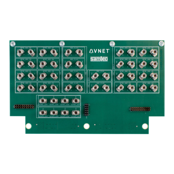
- Page 1 Differential Breakout card for Zynq UltraScale+ RFSoC – Hardware User’s Guide Version 1.0 Page 1 Copyright © 2019 Avnet, Inc. AVNET, “Reach Further,” and the AV logo are registered trademarks of Avnet, Inc. All other brands are the property of their respective owners.
-
Page 2: Table Of Contents
Contents Introduction ......................3 Key Features ..........................3 Support ............................. 3 Pin Assignment .....................5 Digital IO & Power Rails ......................5 RFMC Connector Pin Assignments ..................8 Trace Length Matching ..................10 Board Dimension ....................11 Simulation Data ....................12 Stackup ..........................12 Composite S-parameter ...................... -
Page 3: Introduction
Leverages Samtec RSP-208784-01 screw-mount, straight SMA plug Support For additional documentation, related products, and videos visit the Avnet RFSoC kit page: www.avnet.com/rfsockit If you have questions, please use the Avnet RFSoC Kit forum on our Element 14 ZedBoard Community page: https://www.element14.com/zedboardcommunity Page 3 Differential Breakout card for Zynq UltraScale+ RFSoC –... - Page 4 Figure 1 – Xilinx Zynq® UltraScale+™ RFSoC Evaluation Board with AES-LPA-502 Card Page 4 Differential Breakout card for Zynq UltraScale+ RFSoC – Hardware User’s Guide Hardware User’s Guide...
-
Page 5: Pin Assignment
2 Pin Assignment The following sections provide information on assignment of signals to pins. Digital IO & Power Rails The Xilinx RFMC connector standard provides various digital IO and power rails. The AES-LPA- 502-G provides access to these signals at standard 0.1 mil headers J9, J10 and J29. Figure 2 - Header Pins for RFMC Digital IO Signals Figure 3 - Header Pins for RFMC I2C and Power Rails The tables below show how the GPIO pins have been assigned. -
Page 6: Table 2 - Assignments For Adcio Digital Signals
Table 1 – Assignments for DACIO Digital Signals Signal RFSoC RFMC LPA-502 J888 Pin J9 Pin DACIO_00 DACIO_01 DACIO_02 DACIO_03 DACIO_04 DACIO_05 DACIO_06 DACIO_07 DACIO_08 DACIO_09 DACIO_10 DACIO_11 DACIO_12 DACIO_13 DACIO_14 DACIO_15 DACIO_16 DACIO_17 DACIO_18 DACIO_19 Table 2 - Assignments for ADCIO Digital Signals Signal RFSoC RFMC... - Page 7 Signal RFSoC RFMC LPA-502 J333 Pin J10 Pin ADCIO_04 ADCIO_05 ADCIO_06 ADCIO_07 ADCIO_08 ADCIO_09 ADCIO_10 ADCIO_11 ADCIO_12 ADCIO_13 ADCIO_14 ADCIO_15 ADCIO_16 ADCIO_17 ADCIO_18 ADCIO_19 Table 3 - Assignments for I2C and Power Signal RFSoC RFMC LPA-502 J29 Pin RFMC_I2C_SDA MIO17* J333-E6 RFMC_I2C_SCL MIO18* J333-G6...
-
Page 8: Rfmc Connector Pin Assignments
RFMC Connector Pin Assignments The two tables below show the ZCU111 RFMC LPAF connector pin assignments, as per the Xilinx documentation for the board (table 3-21 of the ZCU111 Evaluation Board User Guide). Figure 4 – RFMC DAC LPAF Connector J94, Vertical Orientation (A1 Upper Right Corner) Page 8 Differential Breakout card for Zynq UltraScale+ RFSoC –... - Page 9 Figure 5 – RFMC RF-ADC LPAF Connector J47, Vertical Orientation (A1 in Upper Right Corner) Page 9 Differential Breakout card for Zynq UltraScale+ RFSoC – Hardware User’s Guide Hardware User’s Guide...
-
Page 10: Trace Length Matching
3 Trace Length Matching Trace lengths for ADC and DAC signal paths on the LPA-502 board are matched per channel as summarized below. Differential pair lengths are matched ADC channel lengths are matched DAC channels lengths are matched ... -
Page 11: Board Dimension
5 Board Dimension All dimensions are in inches. Page 11 Differential Breakout card for Zynq UltraScale+ RFSoC – Hardware User’s Guide... -
Page 12: Simulation Data
6 Simulation Data The following board simulations were performed by Samtec. Stackup Page 12 Differential Breakout card for Zynq UltraScale+ RFSoC – Hardware User’s Guide... -
Page 13: Composite S-Parameter
Composite S-parameter Page 13 Differential Breakout card for Zynq UltraScale+ RFSoC – Hardware User’s Guide Hardware User’s Guide... -
Page 14: Insertion Loss
Insertion Loss Page 14 Differential Breakout card for Zynq UltraScale+ RFSoC – Hardware User’s Guide Hardware User’s Guide... -
Page 15: Return Loss
Return Loss Page 15 Differential Breakout card for Zynq UltraScale+ RFSoC – Hardware User’s Guide Hardware User’s Guide... -
Page 16: Cross Talk
Cross Talk Page 16 Differential Breakout card for Zynq UltraScale+ RFSoC – Hardware User’s Guide Hardware User’s Guide... -
Page 17: Version History
7 Version History Version Date Comment 20 Nov 2019 Initial Release Page 17 Differential Breakout card for Zynq UltraScale+ RFSoC – Hardware User’s Guide...
Need help?
Do you have a question about the AES-LPA-502-G and is the answer not in the manual?
Questions and answers