
Related Manuals for Avnet MaaXBoard 8ULP


Summary of Contents for Avnet MaaXBoard 8ULP
- Page 1 Ultra-Low Power NXP i.MX 8ULP Development Board MaaXBoard 8ULP Hardware User Guide v1.0 October 03, 2023 Page 1...
-
Page 2: Document Control
1 Document Control Document Version: v1.0 Document Date: 10/03/2023 Document Author: Peter Fenn Document Classification: public Document Distribution: public 2 Version History Version Date Comment 10/03/2023 Initial release Page 2... -
Page 3: Table Of Contents
Block Diagram – MaaXBoard 8ULP ............14 MaaXBoard 8ULP SOM Component Locations ........15 MaaXBoard 8ULP BaseBoard Component Locations (Top)....... 16 MaaXBoard 8ULP BaseBoard Component Locations (Bottom) ....17 Boot DIP-Switches, Button-Switches and LEDs ........18 6.8.1 Boot Mode DIP Switches (SW3) ................18 6.8.2... - Page 4 14.4 MCU-LINK Debugger/Programmer Probe (optional for M33 debug) ... 41 14.5 MCU-LINK-PRO Debugger/Programmer Probe (optional for M33 debug)... 42 14.6 Other SBCs, SOMs and Accessories from Avnet Boards ......43 15 MaaXBoard 8ULP Out-of-Box Demo Application ..........45 Page 4...
- Page 5 Figures Figure 1 – MaaXBoard 8ULP Baseboard (BB) and Compute Module (SOM ..... 8 Figure 2 – i.MX 8ULP vs i.MX 8ULP-CS Processor Block Diagram ......12 Figure 3 – MaaXBoard 8ULP Block Diagram ............14 Figure 4 –MaaXBoard 8ULP Memory Compared to EVK ........19 Figure 5 –...
-
Page 6: Hardware Checklist
Search by name: “8ULP-EVK” on NXP SDK builder site at: https://mcuxpresso.nxp.com/en/select Select MIMX8ULP-EVK then click Build MCUXpresso SDK_2.14.1_EVK-MIMX8ULP to download Avnet MaaXBoard 8ULP pre-built Boot image and MaaXBoard 8ULP pre-built Linux BSP image Table 2 – Software Checklist Page 6... -
Page 7: Introduction
5 Introduction MaaXBoard 8ULP has been engineered as two PCBs: • a small SOM (43mm x 36mm) fitted via 2x100-pin connectors onto • a compact Raspberry Pi form-factor baseboard (85mm x 56mm) The baseboard supports multiple communication-, UI and vison interfaces, including: •... -
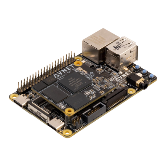
Page 8: Figure 1 - Maaxboard 8Ulp Baseboard (Bb) And Compute Module (Som
Figure 1 – MaaXBoard 8ULP Baseboard (BB) and Compute Module (SOM Page 8... -
Page 9: Maaxboard 8Ulp Info
• MaaXBoard 8ULP QuickStart Card • MaaXBoard 8ULP Product Brief • MaaXBoard 8ULP Hardware User Guide (this document) • NXP MIMX8ULPRM Reference Manual Hardware Setup for Application Development The simplest minimal development setup is shown below This provides +5V power, console debug interfaces and network connectivity... - Page 10 The development setup below adds: • 5MP MIPI-CSI camera and • the ability to read-back current measurements from an external TC66 power measurement USB dongle To this setup a 7-inch touch panel display can also be added via the MIPI-DSI connector on left side of the board Page 10...
-
Page 11: Maaxboard 8Ulp Architecture & Features
4MB QSPI NOR Camera and Display MIPI Interfaces 1x MIPI DSI (4-lane) with PHY (compatible 7-inch and 5-inch displays available from Avnet) 1x MIPI CSI (2-lane) with PHY (compatible 5MP CSI camera available from Arducam) USB Host and Device Interfaces 2x USB 2.0 Host ports (type-A) -
Page 12: Block Diagram - Nxp I.mx8Ulp Processor
Block Diagram – NXP i.MX8ULP Processor Figure 2 – i.MX 8ULP vs i.MX 8ULP-CS Processor Block Diagram Page 12... -
Page 13: 8Ulp Architecture Diagram
8ULP Architecture Diagram Refer to last page of Chapter 2 (page 36) in the i.MX 8ULP Reference Manual (IMX8ULPRM_Rev1_DraftA.pdf or later) for a higher-resolution version of this 8ULP architecture diagram Page 13... -
Page 14: Block Diagram - Maaxboard 8Ulp
Block Diagram – MaaXBoard 8ULP Figure 3 – MaaXBoard 8ULP Block Diagram Page 14... -
Page 15: Maaxboard 8Ulp Som Component Locations
ISSI IS66WVO8M8DALL-200BLI M33-only Octal SPI NOR Flash Adesto ATXP032-CCUE-T M33-only 0V6 LDO for LPDDR4X (NI) Renesas (Intersil) ISL80111RAJZ VDD3V3 dc/dc regulator Richtek RT8010 Ext. Load Switch (NI) Onsemi NCP451AFCT2G Table 3 – Key Components on MaaXBoard 8ULP SOM Page 15... -
Page 16: Maaxboard 8Ulp Baseboard Component Locations (Top)
LED1 RGB LED 3V3 dc/dc regulator Digital Microphone SS5 120-pin B2B connector (lower) RESET button SS5 120-pin B2B connector (upper) USER-1 button FT4232H FTDI 4-port USB bridge USER-2 button Table 4 – Key Components on MaaXBoard 8ULP BaseBoard (top) Page 16... -
Page 17: Maaxboard 8Ulp Baseboard Component Locations (Bottom)
8bit IO expander M.2 Wi-Fi/BT module connector SW3 Boot mode DIP switches U42 JTAG/SWD source selector M.2 module mounting hole U58 Debug UART source selector 8ULP SOM mounting holes Table 5 – Key Components on MaaXBoard 8ULP BaseBoard (bottom) Page 17... -
Page 18: Boot Dip-Switches, Button-Switches And Leds
Boot DIP-Switches, Button-Switches and LEDs 6.8.1 Boot Mode DIP Switches (SW3) DIP switches for manual strapping of boot-mode and config settings are on back of the PCB Signal Selected Function Name Description No Low-Power Boot BT_CFG0 LP boot from M33, boot A35 on demand Boot from eMMC BT_CFG1 Boot from A35/eMMC and M33/QSPI... -
Page 19: Memory Resources
8 MB M33 Octal SPI PSRAM 8 MB FlexSPI1 IS66WVO8M8DALL-200BLI APS6408L-OBM-BA -not used- A35 Octal SPI NOR Flash 64 MB FlexSPI2 MX25UW51345GXDI00 Figure 4 –MaaXBoard 8ULP Memory Compared to EVK Memory Memory 8ULP Avnet Part Type Size Interface Supplier Number... -
Page 20: Wireless Connectivity
6.10 Wireless Connectivity MaaXBoard 8ULP uses a Murata Type-1ZM Wi-Fi 5 and Bluetooth 5 combo module, which is based on the NXP 88W8987 device. Both 2.4 GHz and 5 GHz Wi-Fi operation is supported Interfaces between the NXP 88W8987 based module and the NXP I.MX 8ULP host processor i nclude: •... -
Page 21: Bt Pcm Audio Interface
6.10.3 BT PCM Audio Interface SAI1 is routed from from the I.MX 8ULP via a 3.3V to 1.8V level-shifter, to the Murata 1ZM module’s Bluetooth UART PCM audio interface. (This use of SAI1 interface is identical to what is used for this function on the i.MX 8ULP-EVK) 1ZM Module RT Peripheral... -
Page 22: Table 7 - Wi-Fi/Bt Module Interface
1ZM Module RT Peripheral NXP i.MX 8ULP-EVK NXP i.MX 8ULP- RT Peripheral Pin Name Resource SDK Signal Name Resource and Pin# (on MaaXBoard) M.2 Signal Name (on EVK) BOARD_InitUSDHCPins USDHC1 SD_CLK SD1_CLK WIFI_SD_CLK SDIO_CLK GPIO_SD_B1_01 [D15] [D15] SD_CMD SD1_CMD WIFI_SD_CMD SDIO_CMD GPIO_SD_B1_00 [B16]... -
Page 23: Wi-Fi / Bt Antenna
Figure 6 – Detail of Wi-Fi/BT M.2 Module Implementation 6.10.4 Wi-Fi / BT antenna This board only supports an external antenna, attached via UFL / IPEX MHF connector. The antenna shipped with MaaXBoard 8ULP (as used in regulatory certifications) is Molex p/n: 1461870050 Page 23... -
Page 24: Peripheral Devices And Interfaces
A subset of the remote-debug interface that is on the NXP 8ULP EVK board, is implemented on MaaXBoard 8ULP. This uses the same FT4232H USB to 4-port serial bridge device, but does not support the power-monitoring controls that are implemented on the NXP EVK. -
Page 25: Mipi-Csi Camera
6.11.7 MIPI-CSI Camera The 2-lane, 15-pin MIPI connector pinout is the same as what is used on Raspberry-Pi board Camera Control I/O Processor I/O CAM_PWREN GPIO09_IO08 CAM_I2C_SCL I2C2_SCL CAM_I2C_SDA I2C2_SCL Note: The 5 MP MIPI-CSI MaaXBoard camera (add-on option) is based on the same OV5640 image sensor as used with the NXP i.MX 8ULP-EVK board. -
Page 26: J9: Stereo Audio Jack
6.11.10 J9: Stereo Audio Jack Page 26... -
Page 27: J1: Pi-Hat Compatible 40-Pin Header
6.11.11 J1: Pi-HAT compatible 40-pin header Possible HAT MaaXBoard 8ULP Possible HAT MaaXBoard 8ULP Pin Function Signal Name Pin Function Signal Name 5V_SYS VDD_3V3 I2C_SDA 5V_SYS LPI2C4_SDA I2C_SCL LPI2C4_SCL GPIO / GPCLK0 UART_TX PTF10_LPUART4_TX PTD14 UART_RX PTF11_LPUART4_RX GPIO / RTS... -
Page 28: Mikroe Click Boards
Note: Refer to the following webpage for Raspberry Pi HAT compatibility: https://pinout.xyz/pinout/ 6.11.12 MikroE Click Boards • Over 1100+ Click Boards available (orderable from Avnet) • Inexpensive Pi HAT adapters available (these support 2 Click boards) • Parametric search tool on MikroE website •... -
Page 29: J15: 16-Pin Mikroe Click Shuttle Expansion Header
6.11.14 J15: 16-pin MikroE Click Shuttle expansion header MikroE Click MaaXBoard 8ULP MikroE Click MaaXBoard 8ULP Function Signal Name Function Signal Name PTA8_PWM1 PTB2_ADC_CH1A PTB12_CLICK_INT PTB14_CLICK_RST PTA15_LPUART0_RX PTB6_LPSPI2_CS0 PTA18_LPUART0_TX PTB5_LPSPI2_CLK MISO PTA12_LPI2C1_SCL PTB4_LPSPI4_SOUT MOSI PTB3_LPSPI2_SIN PTA13_LPI2C1_SDA SYS_5V VDD3V3 Table 9 – 16-pin MikroE Click Shuttle expansion header (J15) -
Page 30: Swd/Jtag Debugger 10-Pin Mini-Header
6.11.16 SWD/JTAG debugger 10-pin mini-header • The 10-pin Mini-header by default supports the SWD interface tabled below MCU-LINK MCU-LINK JTAG JTAG JTAG_TMS SWD_IO IF_VREF VDD_3V3 JTAG_TCK SWCLK JTAG_TDO JTAG_TDI IF_TDI IF_ISPEN GND* nRST IF_RST IF_DETECT JTAG_nTRST* Table 10 – SWD/JTAG debugger 10-pin mini-header (J16) *Note: For JTAG interface: Reconfigure pin 7 and pin 9 PCB bridges to support these signals Page 30... -
Page 31: Power Input, Protection And Regulation
$20 https://www.amazon.com/Tester-Eversame-Voltmeter-Ammeter-Braided/dp/B07MGQZHGM Note: An invalid current measurement will be seen if MaaXBoard 8ULP is powered from a USB port from the same PC as the debugger probe! To achieve a useful current measurement, the board must be powered from a separate power- adapter, or the debugger probe must be fully disconnected. -
Page 32: 8Ulp Power Domains
6.12.5 8ULP Power Domains The i.MX 8ULP processor supports multiple power domains as tabled below and detailed on the next page Power domain Components Real-time processor domain (RTD) Arm Cortex-M33 platform Fusion F1 DSP Security subsystem Power management Multiple peripherals System-level components Three GPIO ports: A, B, and C Application processor domain (APD) -
Page 33: Figure 8 - 8Ulp Power Management Scheme
Figure 8 – 8ULP Power Management Scheme (Refer to Chapter 10, page 820 of the NXP reference manual for the high-resolution diagram) Testpoints are provided on the SOM for current measurement of three independent power domains: VDD_DIG0, VDD_DIG1 and VDD_DIG2 (requires use of external test instrument). Page 33... - Page 34 At time of publishing this document, the following new factory-programmed Linux BSP image was in use: maaxboard8ulp-lf-6.1.22-2.0.0-mickledore-20230922-factory Public links in context of previous version (MaaXBoard-8ULP_lf-6.1.1-1.0.0_Yocto_20230630) are tabled below: Resource Links to Avnet Repos Description Pre-built Bootloader image u-boot-maaxboard-8ulp.imx Pre-built Linux BSP image avnet-image-full-maaxboard-8ulp-20230620082521.rootfs.wic...
-
Page 35: Maaxboard 8Ulp Example Applications
7 MaaXBoard 8ULP Example Applications Avnet-Supplied Reference Designs Repo / Application Name Key Board Functions Exercised Location Ref.Design #1: Webserver, Ethernet, MIPI camera, MIPI display, Webserver Out of Box Demo power modes and power measurement Ref.Design #2: Ethernet, MIPI camera, MIPI display Access Control AI Demo Ref.Design #3:... -
Page 36: Known Issues
8 Known Issues The following should be noted when working with the Rev.3 version production MaaXBoard 8ULP Description of Issue Comment / Workaround No known issues at this time 9 Cautionary Notes ESD - Handling precautions for ESD-vulnerable electronic equipment are strongly recommended. It is advised to touch the metal housing of Ethernet or USB connectors, prior to touching any other part of the PCB. -
Page 37: Technical Support
NXP also provide a wealth of online i.MX training and App Note resources, accessible from this page: https://www.nxp.com/design/training:TRAINING-EVENTS 10.2 Avnet-hosted Technical Support Resources Avnet documents & reference designs are available for download from MaaXBoard 8ULP product page: http://avnet.me/MaaXBoard 8ULP Avnet instructional tutorial blogs will also be linked to from: http://avnet.me/MaaXBoard 8ULP... -
Page 38: Disclaimer
12 Disclaimer MaaXBoard 8ULP is engineered for use as a development board (to facilitate product evaluation and system - level prototyping) as well as for use as a sub-assembly in custom OEM end-products. Avnet assumes no liability for modifications that a user chooses to make to MaaXBoard 8ULP. -
Page 39: Maaxboard 8Ulp Accessories
Compatible with all MaaXBoard SBC platforms. • Connects to host via a 4-lane MIPI-DSI interface • Capacitive multi-touch display overlay • Custom displays available via Avnet Embedded Part# (and link): AES-ACC-MAAX-DISP2 (MSRP = $105.00) 14.2 MIPI DSI 5-inch Capacitive Touch LCD Display (optional) •... -
Page 40: Mipi Csi 5 Mp Camera (Optional)
14.3 MIPI CSI 5 MP Camera (optional) • High quality 5 MP image sensor • Compatible with all MaaXBoard SBCs and Raspberry Pi • Attaches to host via 2-lane MIPI CSI ribbon cable • Supports 1080p30, 720p60 and 640x480p90 video •... -
Page 41: Mcu-Link Debugger/Programmer Probe (Optional For M33 Debug)
14.4 MCU-LINK Debugger/Programmer Probe (optional for M33 debug) NXP MCU-LINK Debugger Probe configured for CMSIS-DAP protocol, is supported by multiple IDEs and is available for purchase separately from Avnet Standard MCU-Link features: • High speed USB, • SWD debug, •... -
Page 42: Mcu-Link-Pro Debugger/Programmer Probe (Optional For M33 Debug)
14.5 MCU-LINK-PRO Debugger/Programmer Probe (optional for M33 debug) NXP MCU-LINK-PRO Debugger Probe alternative debugger probe has several enhancements Features in common with MCU-Link: • High speed USB • SWD debug • SWO profiling • VCOM (USB to UART bridge) Advanced MCU-Link-Pro features: •... -
Page 43: Other Sbcs, Soms And Accessories From Avnet Boards
14.6 Other SBCs, SOMs and Accessories from Avnet Boards Avnet’s Advanced Applications Group work in close partnership with key suppliers to develop advanced enablement solutions • Kits / Boards / SOMs / Modules • Reference Designs • Trainings / Tutorials / Blogs avnet.me/avnetboards... - Page 44 Page 44...
-
Page 45: Maaxboard 8Ulp Out-Of-Box Demo Application
8) Use cases - Simulated real world applications, as well as add-on demo options, e.g. Camera based badge-scan security access-control demo (with AWS/Azure dashboard) Standalone - In the most minimal configuration (just MaaXBoard 8ULP without accessories), a subset of the available functions can be exercised from an Internet Browser on the development PC +Accessories –... - Page 46 The simplest / minimum hardware setup needed to access webserver pages from your board is as follows: 1) Connect MaaXBoard 8ULP via Ethernet to the same network router that your PC is connected to. 2) Power-up the board by connecting 5V (from host PC or a power adapter) to the lower USB-C connector Open an Internet browser on the host PC and enter the following address: http://maaxboard8ulp.local:5000/...
- Page 47 4) Power-up the board. After booting completed, login as root at the commandline interface, then set the IP address of the MaaXBoard 8ULP Ethernet port to be on same sub-LAN network as the static IP settings of Ethernet adapter on the host PC. ie. Use this CLI command to set the eth0 IP address: ifconfig eth0 192.168.1.99...
Need help?
Do you have a question about the MaaXBoard 8ULP and is the answer not in the manual?
Questions and answers