
Related Manuals for Lattice Semiconductor MachXO 2280


Summary of Contents for Lattice Semiconductor MachXO 2280
- Page 1 MachXO 2280 Breakout Board Evaluation Kit Evaluation Board User Guide FPGA-EB-02038-1.2 June 2021 Arrow.com. Downloaded from...
- Page 2 The information provided in this document is proprietary to Lattice Semiconductor, and Lattice reserves the right to make any changes to the information in this document or to any products at any time without notice.
-
Page 3: Table Of Contents
Revision History ................................... 37 © 2011-2021 Lattice Semiconductor Corp. All Lattice trademarks, registered trademarks, patents, and disclaimers are as listed at www.latticesemi.com/legal. All other brand or product names are trademarks or registered trademarks of their respective holders. The specifications and information herein are subject to change without notice. - Page 4 Figure A.5. MachXO 2280 ..............................35 © 2011-2021 Lattice Semiconductor Corp. All Lattice trademarks, registered trademarks, patents, and disclaimers are as listed at www.latticesemi.com/legal. All other brand or product names are trademarks or registered trademarks of their respective holders. The specifications and information herein are subject to change without notice.
- Page 5 Table B.1. MachXO 2280 Breakout Board Bill of Materials ....................36 © 2011-2021 Lattice Semiconductor Corp. All Lattice trademarks, registered trademarks, patents, and disclaimers are as listed at www.latticesemi.com/legal. All other brand or product names are trademarks or registered trademarks of their respective holders. The specifications and information herein are subject to change without notice.
-
Page 6: Acronyms In This Document
Watchdog Timer © 2011-2021 Lattice Semiconductor Corp. All Lattice trademarks, registered trademarks, patents, and disclaimers are as listed at www.latticesemi.com/legal. All other brand or product names are trademarks or registered trademarks of their respective holders. The specifications and information herein are subject to change without notice. -
Page 7: Introduction
Thank you for choosing the Lattice Semiconductor MachXO™ 2280 Breakout Board Evaluation Kit! This user guide describes how to start using the MachXO 2280 Breakout Board, an easy-to-use platform for evaluating and designing with the MachXO PLD. Along with the board and accessories, this kit includes a pre- loaded demonstration design. -
Page 8: Features
Evaluation Board User Guide 2. Features The MachXO 2280 Breakout Board Evaluation Kit includes: MachXO 2280 Breakout Board – The board is a 3” x 3” form factor that features the following on-board components and circuits: MachXO 2280 PLD (LCMXO2280C-3FTN256C) ... -
Page 9: Storage And Handling
The preprogrammed demonstration design is an up-counter to drive an LED array. The program shows a clock generator based on the MachXO 2280 on-chip oscillator. The counter module is clocked at ~22 MHz (18 MHz – 26 MHz) to illustrate how low speed timer functions can be implemented with a PLD. The 23-bit up-counter further divides the clock to advance the LED display approximately every 200 ms. - Page 10 © 2011-2021 Lattice Semiconductor Corp. All Lattice trademarks, registered trademarks, patents, and disclaimers are as listed at www.latticesemi.com/legal. All other brand or product names are trademarks or registered trademarks of their respective holders. The specifications and information herein are subject to change without notice.
-
Page 11: Downloading Demo Designs
When the board is connected to a PC with a USB cable, it is recognized by the ispVM System software as a USB Download Cable. The MachXO 2280 can then be scanned and programmed using the ispVM System software. - Page 12 PASS in the Status column. © 2011-2021 Lattice Semiconductor Corp. All Lattice trademarks, registered trademarks, patents, and disclaimers are as listed at www.latticesemi.com/legal. All other brand or product names are trademarks or registered trademarks of their respective holders. The specifications and information herein are subject to change without notice.
-
Page 13: Machxo 2280 Breakout Board
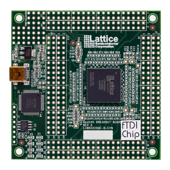
This section describes the features of the MachXO 2280 Breakout Board in detail. 7.1. Overview The Breakout Board is a complete development platform for the MachXO 2280 PLD. The board includes a prototyping area, a USB program/power port, an LED array, and header landings with electrical connections to most of the PLD’s programmable I/O, power, and JTAG pins. -
Page 14: Subsystems
This section describes the principle sub systems for the Breakout Board in alphabetical order. 7.2.1. Clock Sources All clocks for the counter demonstration designs originate from the MachXO 2280 PLD on-chip oscillator. You may use an expansion header landing to drive a PLD input with an external clock source. -
Page 15: Table 7.3. Expansion Header Pin Information (J3)
PL16B_LV_C © 2011-2021 Lattice Semiconductor Corp. All Lattice trademarks, registered trademarks, patents, and disclaimers are as listed at www.latticesemi.com/legal. All other brand or product names are trademarks or registered trademarks of their respective holders. The specifications and information herein are subject to change without notice. -
Page 16: Table 7.4. Expansion Header Pin Information (J4)
PL19B © 2011-2021 Lattice Semiconductor Corp. All Lattice trademarks, registered trademarks, patents, and disclaimers are as listed at www.latticesemi.com/legal. All other brand or product names are trademarks or registered trademarks of their respective holders. The specifications and information herein are subject to change without notice. -
Page 17: Table 7.5. Expansion Header Pin Information (J5)
PT14D © 2011-2021 Lattice Semiconductor Corp. All Lattice trademarks, registered trademarks, patents, and disclaimers are as listed at www.latticesemi.com/legal. All other brand or product names are trademarks or registered trademarks of their respective holders. The specifications and information herein are subject to change without notice. -
Page 18: Table 7.6. Expansion Header Pin Information (J6)
PT16D © 2011-2021 Lattice Semiconductor Corp. All Lattice trademarks, registered trademarks, patents, and disclaimers are as listed at www.latticesemi.com/legal. All other brand or product names are trademarks or registered trademarks of their respective holders. The specifications and information herein are subject to change without notice. -
Page 19: Table 7.7. Expansion Header Pin Information (J7)
PR20B © 2011-2021 Lattice Semiconductor Corp. All Lattice trademarks, registered trademarks, patents, and disclaimers are as listed at www.latticesemi.com/legal. All other brand or product names are trademarks or registered trademarks of their respective holders. The specifications and information herein are subject to change without notice. -
Page 20: Table 7.8. Expansion Header Pin Information (J8)
PR18B_LV_C © 2011-2021 Lattice Semiconductor Corp. All Lattice trademarks, registered trademarks, patents, and disclaimers are as listed at www.latticesemi.com/legal. All other brand or product names are trademarks or registered trademarks of their respective holders. The specifications and information herein are subject to change without notice. -
Page 21: Table 7.9. Expansion Header Pin Information (J9)
PB16D © 2011-2021 Lattice Semiconductor Corp. All Lattice trademarks, registered trademarks, patents, and disclaimers are as listed at www.latticesemi.com/legal. All other brand or product names are trademarks or registered trademarks of their respective holders. The specifications and information herein are subject to change without notice. -
Page 22: Table 7.10. Expansion Header Pin Information (J10)
PB8D © 2011-2021 Lattice Semiconductor Corp. All Lattice trademarks, registered trademarks, patents, and disclaimers are as listed at www.latticesemi.com/legal. All other brand or product names are trademarks or registered trademarks of their respective holders. The specifications and information herein are subject to change without notice. -
Page 23: Figure 7.2. J3/J4 Header Landing Control
Figure 7.3. J5/J6 Header Landing Control © 2011-2021 Lattice Semiconductor Corp. All Lattice trademarks, registered trademarks, patents, and disclaimers are as listed at www.latticesemi.com/legal. All other brand or product names are trademarks or registered trademarks of their respective holders. The specifications and information herein are subject to change without notice. -
Page 24: Figure 7.4. J7/J8 Header Landing Control
Figure 7.5. J9/J10 Header Landing Control © 2011-2021 Lattice Semiconductor Corp. All Lattice trademarks, registered trademarks, patents, and disclaimers are as listed at www.latticesemi.com/legal. All other brand or product names are trademarks or registered trademarks of their respective holders. The specifications and information herein are subject to change without notice. -
Page 25: Machxo 2280 Pld
© 2011-2021 Lattice Semiconductor Corp. All Lattice trademarks, registered trademarks, patents, and disclaimers are as listed at www.latticesemi.com/legal. All other brand or product names are trademarks or registered trademarks of their respective holders. The specifications and information herein are subject to change without notice. -
Page 26: Leds
TP10, VCC3D (VCCAUX) © 2011-2021 Lattice Semiconductor Corp. All Lattice trademarks, registered trademarks, patents, and disclaimers are as listed at www.latticesemi.com/legal. All other brand or product names are trademarks or registered trademarks of their respective holders. The specifications and information herein are subject to change without notice. -
Page 27: Usb Programming And Debug Interface
The USB mini-B socket of the Breakout Board serves as the programming and debug interface. JTAG Programming: For JTAG programming, a preprogrammed USB PHY peripheral controller is provided on the Breakout Board to serve as the programming interface to the MachXO 2280 PLD. Programming requires the ispVM System software. -
Page 28: Board Modifications
The board can be damaged without proper anti-static handling. © 2011-2021 Lattice Semiconductor Corp. All Lattice trademarks, registered trademarks, patents, and disclaimers are as listed at www.latticesemi.com/legal. All other brand or product names are trademarks or registered trademarks of their respective holders. The specifications and information herein are subject to change without notice. -
Page 29: Troubleshooting
8.3.1. Lattice Diamond Programmer Error Lattice Diamond 1.1 reports “File not valid error” from the Programmer interface. Diamond 1.1 is not Programmer compatible with the MachXO 2280 Breakout Board. To program the device, use ispVM System 17.9 or later. © 2011-2021 Lattice Semiconductor Corp. All Lattice trademarks, registered trademarks, patents, and disclaimers are as listed at www.latticesemi.com/legal. -
Page 30: Ordering Information
Submit a technical support case through www.latticesemi.com/techsupport. © 2011-2021 Lattice Semiconductor Corp. All Lattice trademarks, registered trademarks, patents, and disclaimers are as listed at www.latticesemi.com/legal. All other brand or product names are trademarks or registered trademarks of their respective holders. The specifications and information herein are subject to change without notice. -
Page 31: Appendix A. Board Schematics
Figure A.1. MachXO 2280 Breakout Board © 2011-2021 Lattice Semiconductor Corp. All Lattice trademarks, registered trademarks, patents, and disclaimers are as listed at www.latticesemi.com/legal. All other brand or product names are trademarks or registered trademarks of their respective holders. The specifications and information herein are subject to change without n FPGA-EB-02038-1.2... - Page 32 Figure A.2. USB Interface to JTAG © 2011-2021 Lattice Semiconductor Corp. All Lattice trademarks, registered trademarks, patents, and disclaimers are as listed at www.latticesemi.com/legal. All other brand or product names are trademarks or registered trademarks of their respective holders. The specifications and information herein are subject to change without n Arrow.com.
-
Page 33: Figure A.3. Connectors And Leds
Figure A.3. Connectors and LEDs © 2011-2021 Lattice Semiconductor Corp. All Lattice trademarks, registered trademarks, patents, and disclaimers are as listed at www.latticesemi.com/legal. All other brand or product names are trademarks or registered trademarks of their respective holders. The specifications and information herein are subject to change without n FPGA-EB-02038-1.2... -
Page 34: Figure A.4. Machxo 2280
Figure A.4. MachXO 2280 © 2011-2021 Lattice Semiconductor Corp. All Lattice trademarks, registered trademarks, patents, and disclaimers are as listed at www.latticesemi.com/legal. All other brand or product names are trademarks or registered trademarks of their respective holders. The specifications and information herein are subject to change without n Arrow.com. -
Page 35: Figure A.5. Machxo 2280
Figure A.5. MachXO 2280 © 2011-2021 Lattice Semiconductor Corp. All Lattice trademarks, registered trademarks, patents, and disclaimers are as listed at www.latticesemi.com/legal. All other brand or product names are trademarks or registered trademarks of their respective holders. The specifications and information herein are subject to change without n FPGA-EB-02038-1.2... -
Page 36: Appendix B. Bill Of Materials
7M-12.000MAAJ-T © 2011-2021 Lattice Semiconductor Corp. All Lattice trademarks, registered trademarks, patents, and disclaimers are as listed at www.latticesemi.com/legal. All other brand or product names are trademarks or registered trademarks of their respective holders. The specifications and information herein are subject to change without notice. -
Page 37: Revision History
Initial release © 2011-2021 Lattice Semiconductor Corp. All Lattice trademarks, registered trademarks, patents, and disclaimers are as listed at www.latticesemi.com/legal. All other brand or product names are trademarks or registered trademarks of their respective holders. The specifications and information herein are subject to change without notice. - Page 38 www.latticesemi.com Arrow.com. Arrow.com. Arrow.com. Arrow.com. Arrow.com. Arrow.com. Arrow.com. Arrow.com. Arrow.com. Arrow.com. Arrow.com. Arrow.com. Arrow.com. Arrow.com. Arrow.com. Arrow.com. Arrow.com. Arrow.com. Arrow.com. Arrow.com. Arrow.com. Arrow.com. Arrow.com. Arrow.com. Arrow.com. Arrow.com. Arrow.com. Arrow.com. Arrow.com. Arrow.com. Arrow.com. Arrow.com. Arrow.com. Arrow.com. Arrow.com. Arrow.com. Arrow.com. Arrow.com. Downloaded from Downloaded from Downloaded from Downloaded from...
Need help?
Do you have a question about the MachXO 2280 and is the answer not in the manual?
Questions and answers