Table of Contents
Advertisement
Quick Links
Advertisement
Chapters
Table of Contents

Related Manuals for ETAS ES441.1


Summary of Contents for ETAS ES441.1
- Page 1 ETAS ES441.1 Counter and Frequency Module with Sen- sor Supply User Guide...
- Page 2 The data in this document may not be altered or amended without special noti- fication from ETAS GmbH. ETAS GmbH undertakes no further obligation in relation to this document. The software described in it can only be used if the customer is in possession of a general license agreement or single license.
-
Page 3: Table Of Contents
Features of the ES441.1 ........ - Page 4 What to do in the Case of Oversampling by the Calibration Software . . 36 Overview of the Measuring Capabilities of the ES441.1..... . . 36 Overflow.
- Page 5 Troubleshooting ES441.1 Problems ........
- Page 6 ES441.1 ........
-
Page 7: About This Document
Presentation of Instructions The target to be achieved is defined in the heading. The necessary steps for his are in a step-by-step guide: Target definition 1. Step 1 2. Step 2 3. Step 3 > Result ES441.1 - User Guide... -
Page 8: Typographical Conventions
(see chapter 10.1 on page 120). Additional cables and adapters can be obtained separately from ETAS. A list of available accessories and their order designation is located in chapter “Acces- sories” on page 120 of this manual or in the ETAS product catalog. -
Page 9: Basic Safety Notices
• “Intended Use” on page 9 General Safety Information Please observe the Product Safety Notices ("ETAS Safety Notice") and the fol- lowing safety notices to avoid health issues or damage to the device. NOTE Carefully read the documentation (Product Safety Advice and this User's Guide) that belongs to the product prior to the startup. - Page 10 • Route the power cable in such a way that it is protected against abrasion, damages, deformation and kinking. Do not place any objects on the power cable! ES441.1 - User Guide...
- Page 11 • Adhere to the maximum permissible cable lengths! • Do not use any damaged cables! Cables may be repaired only by ETAS! CAUTION Never apply force to insert a plug into a socket. Ensure that there is no contamination in and on the connection, that the plug fits the socket, and that you correctly aligned the plugs with the connection.
- Page 12 Damage of the module and loss of properties acc. to IP67 CAUTION Loss of Features as defined by IP67! Water standing at the pressure balance element damages the membrane! Please observe which way the module is pointing when installing vertically! ES441.1 - User Guide...
- Page 13 Maintenance The product is maintenance-free. Repair If a repair of an ETAS hardware product should become necessary, send the product to ETAS. Cleaning the module housing • Use a dry or lightly moistened, soft, lint-free cloth for cleaning the module housing.
-
Page 14: Es400 Product Family
Fig. 3-1 Central and Decentral Sensor Cabling With the ES400 modules, ETAS provides a decentral solution which consider- ably simplifies the test setup of the sensors. The basic idea of this concept is to install the modules of the ES400 family as close as possible to the sensors, to concatenate the modules with each other and to connect just the first module of this chain with the laptop in the vehicle. -
Page 15: Features Of The Es400 Line
– support of all probes and pressure sensors used in the automotive industry • Innovative, battery-saving power supply management – automatic power-saving feature (“Standby”) – “Wake Up” via the Ethernet interface • Part of the ETAS Tool Suite • Daisy Chain Configuration Tool (stand-alone operation) ES441.1 - User Guide... -
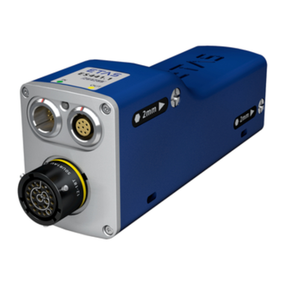
Page 16: Housing
Data” on page 92. Housing A sturdy metal housing is used for the ES441.1; it has ports on the front of the device so it can fit into tight spaces. The ES441.1 is specifically designed to be installed in engine compartment, but also in the passenger cell. -
Page 17: Ports
Front 3.4.1 “Sensor” Port The front of the ES441.1 features a 22-pin Souriau port to which four sensors can be connected using a adapter cable. An individual sensor power supply port is available for each sensor. The use of a “cable tail” or “whip” solution with just one connector makes it possible to change the modules quickly within complex test setups. -
Page 18: Led
Functional State Display State yellow-red flashing Warning 0,5 s yellow reduced / Overload on a sensor supply 0,5 s red reduced voltage channel red illuminated Error during self-test fully bright red illuminated Internal error semi bright ES441.1 - User Guide... -
Page 19: Hardware Description
ES441.1 Housing The ES441.1 Counter and Frequency Module with Sensor Supply is a member of the family of ES400-Modules. The ES441.1 can acquire digital signals at four input channels. There is a sensor supply for every channel For the complete technical data of the ES441.1, refer to the chapter “Technical Data”... -
Page 20: Block Diagram
ETAS Hardware Description Block Diagram The ES441.1 is a module with four identical measurement channels, its own sensor supply for every measurement channel, two shared Ethernet interfaces and a power supply. cmd^ bíÜÉêåÉí `çååÉÅíçê Eeçëí ÇáêÉÅíáçåF bíÜÉêåÉí =`eQ mÜó =K=K=K j_áíLë... -
Page 21: Fig. 4-4 Definition Of The Hysteresis For The Input Channel
The filter characteristics (duration) can be configured in the calibration software. The interfering voltage filter can be disabled if necessary. Inverter The input signal of every channel of the ES441.1 can be inverted independently of the other channels if necessary. Selection takes place in the calibration soft- ware. -
Page 22: Sensor Supply
Hardware Description 4.3.2 Sensor Supply Every sensor that can be switched to the ES441.1 has an individual sensor sup- ply voltage which can be set separately. The cable connected to the sensor port of the ES441.1 transfers both the sen- sor supply voltage and the sensor output voltage for the sensor. -
Page 23: Data Transfer
Message Format “XCP on UDP” (Schematic) Using the UDP/IP standard for data transfer makes it possible to connect the modules directly to a PC, a router or a switch. In XCP communication, the PC has the master function. ES441.1 - User Guide... -
Page 24: Realization
The communication protocol used by the ES400 family makes it possible for third-party suppliers to use the communication protocol for their own, non- ETAS applications once the modules have been configured with the „ES4xx Configuration Tool from ES4xx_DRV_SW“ . 4.4.2... - Page 25 IEEE1588 (Precision Time Protocol). The modules add the time stamp to the Ethernet data package for every measure date. The combination of time stamp synchronization, full duplex and time slice pro- cedure results in a very high reference data rate of the modules. ES441.1 - User Guide...
-
Page 26: Examples
4.4.3 Examples Example 1 Fig. 4-7 on page 26 shows an example of an application with three concatenated ES400 modules with the same acquisition rates. The transfer scheme for this configuration is shown in Fig. 4-8 on page 26. jlari=N jlari=O jlari=P píÉääÖê∏≈Éå... -
Page 27: Fig. 4-9 Time-Multiplex Data Transfer Between An Es400 Module Chain And A Pc
Example 2 Fig. 4-9 on page 27 shows an example in which three modules with different acquisition rates are linked to each other. The transfer scheme for this configuration is shown in Fig. 4-10 on page 27. jlari=N jlari=O jlari=P píÉääÖê∏≈Éå... -
Page 28: Power Supply
ES400 modules with supply voltages between 5 V and 50 V DC over the entire temperature range. With the power supply management of the ES441.1, you can use an automatic power-saving feature (“Standby”) as well as a “Wake Up” function via the Ether- net interface. - Page 29 ETAS Example 1: For module chains which are equipped exclusively with ES410.1 or ES441.1, ETAS recommends the use of Y boost cables if the length of the module chain is longer than 10 modules. Example 2: For module chains which are equipped exclusively with ES411.1 or ES413.1 or ES421.1, ETAS recommends the use of Y boost cables if the length of the mod-...
- Page 30 With a minimum voltage of 9 V, no additional feeding is necessary with a Y cable if the module chain consists of the following modules: • five ES420.1 or ES421.1 and • two ES415.1 (with sensor feeding) and • one ES441.1 NOTE All examples apply at 85 °C ambient temperature. ES441.1 - User Guide...
-
Page 31: Configuration
ETAS Configuration The configuration of the ES441.1 is performed entirely via the GUI within INCA. The configuration of the individual channels is saved either in INCA or in the individual ES400 modules. In the first case, you can prepare settings for spe- cific measure tasks, e.g. -
Page 32: Functional Description
“Measuring Sensor Signals” on page 32 • “Definitions” on page 33 • “Signal Sampling” on page 35 • “Overview of the Measuring Capabilities of the ES441.1” on page 36 • “Overflow” on page 37 • “Measuring Signal State” on page 37 •... -
Page 33: Definitions
Definitions This section defines signals which are used in the description of the measuring capabilities of the ES441.1. NOTE All definitions in this section are definitions for digital signals. 5.2.1 Tab. -
Page 34: State
If the period starts with an active-inactive edge, the period consists of a sequence of an inactive pulse with a subsequent active pulse. fåéìí mÉêáçÇ páÖå~ä ^ÅíáîÉ få~ÅíáîÉ qáãÉ Fig. 5-3 Period, Starting with an Active-Inactive Edge ES441.1 - User Guide... -
Page 35: Cycle
Signal Sampling 5.3.1 Sampling and Rates The sampling rate can be selected independently for every channel of the ES441.1 in fixed steps in the calibration software. The data is sampled synchro- nously at a fixed sampling rate. fåéìí páÖå~ä ^ÅíáîÉ... -
Page 36: What To Do In The Case Of Oversampling By The Calibration Software
(see Fig. 5-7 on page 36). In such a case, the last valid measure value acquired is used again. Overview of the Measuring Capabilities of the ES441.1 The ES441.1 module can acquire digital signals at the four input channels and evaluate these using various measuring capabilities: Measuring Capability... -
Page 37: Overflow
Fig. 5-8 Measuring the Active and Inactive State (Fixed Measure Rate) Which input channels of the ES441.1 state should be measured on can be specified in the calibration software. In the additional signal "stateCombined", the state of the four input channels at any one time is shown together in one byte. -
Page 38: Counter
• Counter modes with parameters which can be configured with restric- tions These measurement modes of the ES441.1 in its function as a counter can be divided into four groups: “Standard without Qualifying Signal” Counter Mode The signal at the measurement channel is counted regardless of signals at other measurement channels (see section 5.7.2 on page 39). -
Page 39: Standard Without Qualifying Signal" Counter Mode
The counter assigned to the measurement channel is configured as an up-counter. In this mode, the ES441.1 can count edges with the following measurement modes in accordance with the configuration in the calibration software: •... -
Page 40: Standard With Qualifying Signal" Counter Mode
(trigger channel) in the “Standard with qualifying signal” counter mode. Depending on the configuration in the calibra- tion software, the input signal of the qualifying channel is evaluated and mea- surement controlled at the assigned measurement channel. ES441.1 - User Guide... - Page 41 ETAS Functional Description In this mode, the ES441.1 can count edges with the following additional mea- surement modes: • Up-counter with measurement control (triggering) in acc. with – the state of the qualifying signal, – the edges of the qualifying signal and •...
-
Page 42: Fig. 5-13 Counting The Inactive-Active Edges With Resetting With The Inactive-Active Edge
Counting the Inactive-Active Edges when the Qualifying Signal is Active In the example shown in Fig. 5-14, the active-inactive edge of the assigned qualifying signal resets the counter. The signal at the measurement channel is counted when the qualifying signal is active. ES441.1 - User Guide... -
Page 43: Fig. 5-15 Counting The Inactive-Active Edges In "Up/Down1" Counter Mode
Count Direction Control in acc. with the State of the Qualifying Signal In this counter mode, the ES441.1 is configured as an up-/down-counter with the count direction being controlled in acc. with the state at the assigned qual- ifying channel (trigger channel). The counter can be positive or negative. -
Page 44: Up/Down" Counter Mode
Counter in Free Running Mode (no resetting of the counter). fåéìí páÖå~ä ^ÅíáîÉ få~ÅíáîÉ qáãÉ nì~äáÑóáåÖ páÖå~ä ^ÅíáîÉ få~ÅíáîÉ qáãÉ Fig. 5-17 “Up/Down” Counter Mode When to use the “Up/Down” counter mode: • Acquisition of data from incremental transducers • Position determination ES441.1 - User Guide... -
Page 45: X1", "X2" And "X4" Counter Modes
Depending on the selected counter mode, the input signal of the qualifying channel is evaluated and measurement controlled at the assigned measure- ment channel. In this mode, the ES441.1 can count edges with the following additional mea- surement modes: Up-/down-counter with control of the count direction in acc. with •... - Page 46 X1 Counter Mode “X2” Counter Mode In counter mode “X2”, the ES441.1 is configured as an up-/down-counter with the count direction being controlled by comparing the state of the signals at the measurement channel and the qualifying channel (trigger channel). The inac- tive-active and active-inactive edges are counted at the measurement channel: •...
- Page 47 Functional Description “X4” Counter Mode In counter mode “X4”, the ES441.1 is configured as an up-/down-counter whose measurement channel and its assigned second channel are analyzed as equal channels. Both edges of the signals at the measurement channel and at the assigned second channel are evaluated according to different rules.
-
Page 48: Time Measurement
The active and/or inactive duration of the input signal can be determined with every measurement channel. The period of time for measuring this time is configured in the calibration software. The ES441.1 can determine active and inactive times with the following time-controlled mea- surement modes: •... -
Page 49: Fig. 5-21 Measuring The Active Time During The Last Period
Fig. 5-22 Measuring the Active Time of a Cycle Measuring the Active Time Between Two Sampling Points fåéìí páÖå~ä ^ÅíáîÉ få~ÅíáîÉ ^ÅíáîÉ qáãÉ qáãÉ Fig. 5-23 Measuring the Active Time Between Two Sampling Points ES441.1 - User Guide... -
Page 50: Measurement Modes With A Qualifying Signal
This mea- surement mode can only be used if "Measuring until the last current sampling point" is selected in the calibration software. With this assignment, the ES441.1 can determine active and inactive times using the additional measurement modes: •... -
Page 51: Frequency Measurement
ES441.1: f = 1 / T The values determined are linked to an additional calculation error coupled to the resolution of the ES441.1 (see section 5.9.5 on page 54). 5.9.1 Measurement Modes In the calibration software, parameters and measurement modes can be selected for frequency measurement for every measurement channel: •... -
Page 52: Measurement Modes Without A Qualifying Signal
With the frequency, determined on the basis of the measuring of the duration of the last cycle, and the number of periods per cycle, the ES441.1 can calculate the number of revolutions per minute (RPM) (see example in section 5.11 on page 57). -
Page 53: Fig. 5-29 Determination Of The Sign Of The Acquired Frequency Value When The Qualifying
Sign Assignment in acc. with the State of the Qualifying Signal fåéìí páÖå~ä ^ÅíáîÉ få~ÅíáîÉ qáãÉ nì~äáÑóáåÖ páÖå~ä ^ÅíáîÉ få~ÅíáîÉ qáãÉ Fig. 5-29 Determination of the Sign of the Acquired Frequency Value when the Qualifying Signal is Active ES441.1 - User Guide... -
Page 54: Measuring The Duty Cycle
The state of the signal at the qualifying channel is evaluated. In the example (see Fig. 5-29 on page 53), the ES441.1 was configured in the calibration soft- ware in such a way that the sign of the determined frequency value is set to “+”... - Page 55 In the case of low frequencies, measurement accuracy is mainly governed by the error of the integer division. In the case of high frequencies, the resolution of the internal timebase of the ES441.1 has a greater influence on measure- ment accuracy.
-
Page 56: Timeout (Monitoring The Input Signal)
A check is carried out to see whether at least one signal change has taken place within this time. If there is no signal change, no new measure values can be determined. Depending on the measuring capability activated, the ES441.1 assigns fixed values to all sample values which follow in terms of time with the Timeout function. -
Page 57: Example
Fig. 5-32 16-2 "Speed Sensor" Wheel To be able to determine a speed with the ES441.1, a cycle has to be defined in the configuration software, for example: 1 revolution = 1 cycle = (16-2) periods The module always counts complete cycles. The result is a frequency or num- ber of revolutions per minute. -
Page 58: Getting Started
CAUTION Potential equalization in the vehicle over the shield of the Ethernet connecting cables of modules may occur! Mount the modules only to components with the same electrical potential or insulate the modules from the components. ES441.1 - User Guide... -
Page 59: Guarantee Of Features As Defined By Ip67
(cascading). The two inte- grated assembly elements also make it possible to screw the modules directly onto other components (parts of the vehicle body, units). ES441.1 - User Guide... -
Page 60: Fig. 6-3 Accessing The Integrated Assembly Elements
– on DIN rails with ES4xx angle brackets (right) – on other components • Attaching ES400 modules with cable fasteners: – on DIN rails with ES4xx angle brackets (left) – on DIN rails with ES4xx angle brackets (right) – on other components ES441.1 - User Guide... -
Page 61: Connecting Several Es400 Modules Mechanically
1. Position the modules to be connected in the required order. NOTE Both modules’ ports must point left. 2. Position the modules so that their fronts are in a line. 3. Hold the two modules together firmly on their outer sides. ES441.1 - User Guide... -
Page 62: Fig. 6-6 Connected Es400 Modules
To connect the ES400 module to other modules, you require a 2 mm Allen key (minimum length 20 mm). To connect to other modules: 1. Assemble other modules in accordance with the procedure described in the section 6.2.2 on page ES441.1 - User Guide... -
Page 63: Attaching Es400 Modules To Other Components Using The Integrated As
Preparing the Component To cut the thread in the component: 1. Cut two M3 threads into the selected component. The threads should be cut 8 mm deep. NOTE Use the drilling template (see Fig. 6-13 on page 73). ES441.1 - User Guide... - Page 64 You can only successively screw additional modules, but not module blocks, onto the right-hand side of this module. To connect the ES400 module to other modules, you require a 2 mm Allen key (minimum length 20 mm). ES441.1 - User Guide...
-
Page 65: Attaching Es400 Modules On Din Rails With The Integrated Assembly Ele
1. Connect the module with the ES4xx angle bracket (left). 2. Connect the module with additional modules (as required). 3. Connect the ES4xx angle bracket with the DIN rail. Fig. 6-9 Fastening to an ES4xx Angle Bracket (left) using the Integrated Assembly Elements ES441.1 - User Guide... - Page 66 5. Insert the hex key in the other hexagon head of the module. 6. Screw the parts together by turning the hex key clockwise to the stop within the module. NOTE Screw the two parts together without canting the threads! Both parts are now completely connected mechanically. ES441.1 - User Guide...
-
Page 67: Attaching Es400 Modules To Other Components With Screws
Here, you connect the ES400 module to the component using two additional M3 screws which are screwed into the drill holes of the component. The inte- grated assembly elements of the module are not used. Fig. 6-10 Attaching to Other Components Using Additional Screws ES441.1 - User Guide... - Page 68 4. Screw the screw from the right-hand side of the component into the module. NOTE Screw the two parts together without getting them off- thread! Both parts are now connected mechanically on one side. 5. Insert the other screw into the other hole in the component. ES441.1 - User Guide...
-
Page 69: Attaching Es400 Modules On Din Rails Using Screws
1. Connect the module with additional modules (as required). 2. Connect the module with the ES4xx angle bracket (right). 3. Connect the ES4xx angle bracket with the DIN rail. Fig. 6-11 Fastening on DIN Rails with Additional Screws ES441.1 - User Guide... - Page 70 (right). 6. Fasten the screw with the module from the right side of the ES4xx angle bracket. NOTE Screw the two parts together without canting the threads! Both parts are now completely connected mechanically. ES441.1 - User Guide...
-
Page 71: Attaching Es400 Modules To Other Components Using Cable Fasteners
(see Fig. 6-12 on page 71). Just use cable fasteners to quickly attach the modules to other components in the test environment in the imme- diate proximity of the measuring points. CAUTION When assembling the modules, observe the admissible temperature range of the cable fasteners used! ES441.1 - User Guide... - Page 72 DIN rail. 3. Engage the ES4xx angle bracket in the DIN rail by pressing on the ES4xx angle bracket or the module. The module connected with the ES4xx angle bracket is fas- tened to the DIN rail. ES441.1 - User Guide...
-
Page 73: Drilling Template
ETAS Getting Started Drilling Template Fig. 6-13 Drilling Template ES441.1 - User Guide... -
Page 74: Applications
ES441.1 with additional ETAS Modules for MC Applications The ETAS Daisy Chain concept enables a simple network architecture since only the ES441.1 or the first module of the module chain is connected with the PC or with the "ETH" port of the ES59x.1. -
Page 75: Es441.1 With Additional Etas Modules (Rapid Prototyping Application)
Vehicle, Test Bench, Motor , ... Fig. 6-15 ES441.1 with ES910.3 and additional ETAS Modules for Rapid Prototyping Applications The concept of the ES4xx/ES63x/ES93x product family to install the modules as close as possible to the sensors, the chain the modules with each other, and to connect only the first module of this chain with the ES910.3 or the RTPRO-... -
Page 76: Wiring Examples
ES595 ES411 ES413 ES420 ES430 ES410 ES415 ES421 ES432 ES441 Fig. 6-16 ES400 Modules with additional ETAS Modules (Measurement and Calibration) Cable in Function Order name Fig. 6-16 Power supply cable CBP120, CBP1205 Host connection cable CBE100 Power supply and Ethernet cable Daisy Chain... -
Page 77: Es400 Modules With Additional Etas Modules And Drive Recorder
Tempera- Frequency, Exhaust Voltage ture Counter Results, Pressure Times Fig. 6-17 ES400 Modules with additional ETAS Modules and Drive Recorder (Measurement and Calibration) Cable in Function Order name Fig. 6-17 ES520-, ES59x-, ES6xx-, ES1120- or ES1135- CBE130, CBE140 Ethernet cable... -
Page 78: Es400 Modules With Es910.3 (Rapid Prototyping)
Power supply and Ethernet cable Daisy Chain CBEP430, modules CBEP4305 ETK connection cable CBM150 5, 6 CAN/LIN/FLX connection cable (CAN/LIN/ CBCFI100 FLX combined) at ES910.3, at ES921.1 CAN connection cable (CAN only), at ES910.3, CBAC130, at ES921.1 CBAC140, CBAC150, CBCX130 ES441.1 - User Guide... -
Page 79: Es400 Modules With Es910.3 And Drive Recorder (Rapid Prototyping)
Cable in Function Order name Fig. 6-19 Ethernet adapter cable (100 Mbit/s) CBAE330 (con- nected to cable Ethernet connection cable(1 Gbit/s) CBE230 (con- nected to cable Power supply and Ethernet cable Daisy Chain CBEP430, modules CBEP4305 ES441.1 - User Guide... -
Page 80: Es400 Modules With Etas Rtpro-Pc (Rapid Prototyping)
ETAS 6.5.5 ES400 Modules with ETAS RTPRO-PC (Rapid Prototyping) Ether net USB2 Power Supply Daisy Chain Modules ES581.4 ES411 ES413 ES420 ES430 ES410 ES415 ES421 ES432 ES441 Fig. 6-20 ES400 Modules with ETAS RTPRO-PC (Rapid Prototyping) Cable in Function Order name Fig. -
Page 81: Wiring
Accessories” on page 105. 6.6.1 “Sensor” Port To connect the sensors with the ES441.1, you can use different standard and adapter cables. Detailed information about the cables offered by ETAS is located in chapter “Cable for the Connection "Sensor"” on page 115. -
Page 82: Fig. 6-21 Es441.1 With Es4Xx_Bridge
“OUT” port of the ES441.1 of the last module of the chain towards the PC. 3. Connect the combined Ethernet and power supply cable to the “IN” port of the ES441.1 of the next module towards the end of the chain. 4. Connect the supply voltage connector of the combined Ether- net and power supply cable to the desired power supply. -
Page 83: Troubleshooting Problems
LED Displays Please observe the LEDs which provide information on the functions of the interface and the ES441.1 (see the chapter “LED” on page 18) to be able to judge the operational state of the ES441.1 as well as troubleshooting mea- sures. - Page 84 Daisy Chain modules on a PC card that supports the NDIS protocol. with multi-core processor? Are you using ES441.1 mod- Operate the ES441.1 modules at the ules common with other beginning of the module chain close to ES4xx modules? the host (PC, drive recorder).
- Page 85 Switch the module off and on again. Load the measuring configuration again. If the LED continues to show red, send the module to ETAS for repair. The firmware of Is the module to be updated Update the firmware of these ETAS...
-
Page 86: Problems And Solutions
Windows 7, 8.1 and 10 systems. Network security policies, however, may request the APIPA mechanism to be disabled. In this case, you cannot use a network adapter which is configured for DHCP to access ETAS hardware. The ETAS Network Manager displays a warning message. -
Page 87: Search For Ethernet Hardware Fails
Whenever you switch from a DHCP company LAN to the ETAS hardware net- work, it takes at least 60 seconds until ETAS hardware can be found. This is caused by the operating system’s switching from the DHCP protocol to APIPA, which is being used by the ETAS hardware. - Page 88 Setting the Registry Key autodisconnect: 1. Open the Registry Editor: Windows 7, 8.1: 1.1 Click on the Windows symbol. 1.2 Enter regedit in the entry field. 1.3 Push <E >. NTER ES441.1 - User Guide...
-
Page 89: Personal Firewall Blocks Communication
Ethernet hardware at all, although the configuration parameters are correct. Some actions in ETAS products can lead to problems if the firewall is not prop- erly parameterized, e.g. when opening the experiment environment in ASCET or for the hardware search by INCA or HSP. - Page 90 Below is a sample description about how to configure the Windows firewall if the hardware access is being blocked. Solution for Windows Firewall, user with administrator rights Enabling ETAS products in the firewall control: 1. Open the Control Panel: Windows 7, 10: 1.1 Click on the Windows symbol.
- Page 91 *.ini files are modified during the work. The ETAS software must be installed by an administrator in any case. It is rec- ommended that the administrator ensures that the ETAS product or the pro- cesses are added to the list of selected exceptions of the Windows Firewall after the installation.
-
Page 92: Technical Data
F 00K 123 456 Ordering number of the product, see chapter 10.1 on page 120 Operating voltage range (DC), Power consumption Labeling for WEEE, see chapter 8.6 on page 96 Marking for CE conformity (Chapter 8.3 on page 95) ES441.1 - User Guide... -
Page 93: Standards And Norms
Shocks per direction and axis: 10, Units under test: active ISO 16750-3, Sec. 4.3 Drop test Number of drops: 2, Height: 1 m, Surface: concrete, steel Units under test: passive ISO 16750-4, Sec. 5.2 Phased temperature test ES441.1 - User Guide... -
Page 94: Environmental Conditions
Works on the module may be executed only by qualified technical personnel. 8.1.4 Maintenance the Product Do not open or change the module! Works on the module housing may be exe- cuted only by qualified technical personnel. Send defect modules to ETAS. ES441.1 - User Guide... -
Page 95: Cleaning The Product
People's Republic of China with a China RoHS label attached to the product or its packaging. CE conformity With the CE mark attached to the product or its packaging, ETAS confirms that the product corresponds to the product-specific, applicable directives of the European Union. -
Page 96: Product Return And Recycling
The user is obligated to separate the waste equipment and to provide it to the WEEE return system for reuse. The WEEE Directive applies to all ETAS devices, but not to external cables or batteries. Additional information about the recycling program of ETAS GmbH is available from the ETAS sales and service locations (see chapter “Contact Information”... -
Page 97: System Requirements
"Allow the computer to turn off this device to save power". 8.9.2 Software To configure the ES441.1 and for control and data acquisition, you need soft- ware in the following versions: • INCA V6.2.0 with ES400 INCA Add-On V1.1.3 and higher •... -
Page 98: Electrical Data
ETAS Technical Data Operating the ES441.1 with limited function scope (amongst others no usage of measurement methods with qualifiying signal) is possible using the follow- ing software versions: • INCA V5.4.1 with ES400 INCA Add-On V1.1.0 and higher • ES4xx Configuration Tool V1.1.0 and higher from ES4xx_DRV_SW (stand-alone operation) •... -
Page 99: Host Interface
Polarity inversion protection, load With CBEP410, CBEP4105, CBEP415, dump protection CBEP4155, CBEP420, CBEP4205, CBEP425, CBEP4255, CBEP430, CBEP4305 cable Overvoltage category (AC mains sup- ply) : The module may be used only with central load dump protection. ES441.1 - User Guide... -
Page 100: Sensor Power Supply
Accuracy of the sensor supply voltage ±5 with 3 k load Resistance of sensor supply voltage outputs including CBAV411.1-2 cable Ripple voltage V (measurement lim- ited to 80 MHz) Max. voltage drift (temperature) +1.2 mV/K Output current Output current protection ES441.1 - User Guide... -
Page 101: Input Channels
60 V DC / 30 V AC Maximum Input voltage Input-to-input: (wet environment) 35 V DC / 16 V AC Input-to-ground of voltage supply or housing: 35 V DC / 16 V AC Input impedance > 2 M || < 250 pF ES441.1 - User Guide... -
Page 102: Pin Assignment
““IN” Connector” on page 102 • ““OUT” Connector” on page 103 • ““Sensor” Connector” on page 104 NOTE All connectors are shown with a view of the front of the ES441.1. All shields are at case potential. 8.11.1 “IN” Connector Fig. 8-2 “IN” Connector... -
Page 103: Out" Connector
Operating voltage UBatt Operating voltage Ground Ground Received data, plus Send data, minus Received data, minus Ground Ground Send data, plus The following socket is mounted on "OUT" connector: LEMO 1B 8-pin A-coding (connection identified in yellow) ES441.1 - User Guide... -
Page 104: Sensor" Connector
Sensor channel 1, input - CH1 TEDS- Sensor channel 1, TEDS- CH2 TEDS- Sensor channel 2, TEDS- CH3 TEDS- Sensor channel 3, TEDS- CH4 TEDS- Sensor channel 4, TEDS- TEDS- Cable, TEDS- *): connected with operating voltage ground ES441.1 - User Guide... -
Page 105: Cables And Accessories
“Cable for the Connection "Sensor"” on page 115 • “Protective Caps” on page 118 • “Angle Brackets” on page 119 NOTE Only use ETAS cables at the interfaces of the module. Adhere to the maxi- mum cable lengths! ES441.1 - User Guide... -
Page 106: Combined Ethernet And Power Supply Cable
Connect the power cable only with a suitable vehicle battery or with a suitable lab power supply! The connection to power outlets is not allowed! To prevent an inadvertent insertion in power outlets, ETAS recommends to equip the combined ethernet and power supply cables with safety banana plugs in areas with power outlets. -
Page 107: Cbep410.1 Cable
(MINI flat automotive fuse, quick-response, 3 A, 58 V). Robust, waterproof and dust-proof (IP67). Temperature rated for: -40 °C to +125 °C / -40 °F to +257 °F Product Length Order number CBEP4105.1-3 F 00K 110 026 ES441.1 - User Guide... -
Page 108: Cbep415.1 Cable
(MINI flat automotive fuse, quick-response, 3 A, 58 V). Robust, waterproof and dust-proof (IP67). Temperature rated for: -40 °C to +125 °C / -40 °F to +257 °F Product Length Order number CBEP4155.1-5 F 00K 110 027 ES441.1 - User Guide... -
Page 109: Cbep420.1 Cable
(MINI flat automotive fuse, quick-response, 3 A, 58 V). Robust, waterproof and dust-proof (IP67). Temperature rated for: -40 °C to +125 °C/ -40 °F to +257 °F Product Length Order number CBEP4205.1-3 F 00K 110 041 ES441.1 - User Guide... -
Page 110: Cbep425.1 Cable
(MINI flat automotive fuse, quick-response, 3 A, 58 V). Robust, waterproof and dust-proof (IP67). Temperature rated for: -40 °C to +125 °C / -40 °F to +257 °F Product Length Order number CBEP4255.1-3 F 00K 110 029 ES441.1 - User Guide... -
Page 111: Cbep430.1 Cable
(MINI flat automotive fuse, quick-response, 3 A, 58 V). Robust, waterproof and dust-proof (IP67). Temperature rated for: -40 °C to +125 °C / -40 °F to +257 °F Product Length Order number CBEP4305.1-0m5 0.5 m F 00K 110 030 ES441.1 - User Guide... -
Page 112: Ethernet Cable
(MINI flat automotive fuse, quick-response, 3 A, 58 V). Robust, waterproof and dust-proof (IP67). Temperature rated for: -40 °C to +125 °C / -40 °F to +257 °F Product Length Order number CBE401.1-0m5 0.5 m F 00K 106 128 ES441.1 - User Guide... -
Page 113: Cbe430.1 Cable
Can also be used to connect ES4xx via PC, ES600 or ES1135 alter- natively while keeping cable installation through bulkhead. Robust, waterproof and dust-proof (IP67). Temperature rated for: -40 °C to +125 °C / -40 °F to +257 °F Product Length Order number CBEX400.1-3 F 00K 105 294 ES441.1 - User Guide... -
Page 114: Es4Xx_Bridge
ETAS 9.2.6 ES4xx_BRIDGE Fig. 9-16 ES4xx Bridge Ethernet bridge connecting blocked ES400 modules. Facilitates very compact measurement setups. IP67 compliant. Product Order number ES4xx_BRIDGE F 00K 105 684 ES441.1 - User Guide... -
Page 115: Cable For The Connection "Sensor
Temperature rated for: -40 °C to +125 °C Product Length Order number CBAV400.1-0m3 0.3 m F 00K 104 916 ES441.1 - User Guide... -
Page 116: Cbav411.1 Cable
You can customize the open connection of sensor cable CBAV411.1 and adapt it to the specific plug connector system of your measuring setup. Temperature rated for: -40 °C to +125 °C Product Length Order number CBAV411.1-2 F 00K 104 918 ES441.1 - User Guide... -
Page 117: Cbav417.1 Cable
Measurement channel [n], sensor supply GND *) *): connected with operating voltage Ground Notes about the Application Temperature rated for: -40 °C bis +125 °C Product Length Order number CBAV417.1-0m3 0.3 m F 00K 111 855 ES441.1 - User Guide... -
Page 118: Protective Caps
ETAS Protective Caps The connections "IN" and "OUT" of the ES441.1 can be protected with different protective caps according to the operating conditions. 9.4.1 Protective Caps supplied The "IN" and "OUT" ports of the ES4xx are covered with simple dust and trans- port caps on delivery. -
Page 119: Angle Brackets
Angle Bracket for mounting ES4xx modules to a DIN rail 35 x 7.5 (EN 60715 TH35). Stainless steel V2A. For mounting on right side of an ES4xx module. Product Order number Angle bracket right F 00K 107 176 ES441.1 - User Guide... -
Page 120: Ordering Information
(see chapter 10.2.1 on page 120). 10.2 Accessories 10.2.1 Cables NOTE If you require customized cables, please contact your ETAS contact partner or sales.de@etas.com. Cables for the connectors "IN" and "OUT" Ethernet cable Order name Short name Order number Ethernet Chain Connection Cable, Lemo CBE400.2-3... - Page 121 Supply Cable, Lemo 1B FGL - Lemo 1B FGA - Banana (8fc-8mc-2mc), 0m5 Ethernet Chain Connection and Power CBEP4305.1- F 00K 110 030 Supply Cable, Lemo 1B FGL - Lemo 1B FGA - Safety Banana (8fc-8mc-2mc), 0m5 ES441.1 - User Guide...
-
Page 122: Protective Caps
F 00K 107 175 ES4xx Angle Bracket right ES4xx_AB_R F 00K 107 176 10.2.4 Calibration NOTICE ETAS recommends a calibration interval of 12 months. 10.2.4.1 Factory calibration Factory calibration service • Verification of measurement accuracy • Issue a standard-compliant calibration certificate... - Page 123 Issue of internationally recognized, ISO/IEC 17025 compliant calibration certificates for "pre-adjustment" and "post-adjustment" Order name Short name Order number DAkkS adjustment service for ES441 DAkkS_A_ES441 F-00K-111-778 1. Accreditation by Deutsche Akkreditierungsstelle (DAkkS) 2. Supervision of the calibration certificate by DAkkS ES441.1 - User Guide...
-
Page 124: Contact Information
Germany Internet: www.etas.com ETAS Subsidiaries and Technical Support For details of your local sales office as well as your local technical support team and product hotlines, take a look at the ETAS website: ETAS subsidiaries Internet: www.etas.com/en/contact.php ETAS technical support Internet: www.etas.com/en/hotlines.php... -
Page 125: Figures
ES441.1 Housing ........ - Page 126 ES441.1 with ES4xx_BRIDGE ........
- Page 127 Angle Bracket Right ..........119 ES441.1 - User Guide...
-
Page 128: Index
DAkkS ......123 Master function .....23 ES441.1 - User Guide... - Page 129 ......9 Safety precautions ....9 ES441.1 - User Guide...
Need help?
Do you have a question about the ES441.1 and is the answer not in the manual?
Questions and answers