Table of Contents
Advertisement
Quick Links
Advertisement
Chapters
Table of Contents

Related Manuals for ETAS ES441.1


Summary of Contents for ETAS ES441.1
- Page 1 ES441.1 Counter and Frequency Module with Sensor Supply User’s Guide...
- Page 2 The data in this document may not be altered or amended without special noti- fication from ETAS GmbH. ETAS GmbH undertakes no further obligation in rela- tion to this document. The software described in it can only be used if the customer is in possession of a general license agreement or single license.
-
Page 3: Table Of Contents
Features of the ES441.1 ........ - Page 4 What to do in the Case of Oversampling by the Calibration Software Overview of the Measuring Capabilities of the ES441.1 ....39 Overflow ..........39 Measuring Signal State .
-
Page 5: Fig. 6-17 Es400 Modules With Additional Etas Modules And Drive Recorder
LED Displays ..........93 Troubleshooting ES441.1 Problems ....... 93 Problems and Solutions . - Page 6 9.4.1 Protective Caps supplied ....... 128 ES441.1 - User’s Guide...
- Page 7 11 ETAS Contact Addresses ........
-
Page 8: About This Manual
(serious) injury, if not avoided. CAUTION! identifies a hazard with low risk that could result in minor or medium physical injuries or property damages if not avoided. ES441.1 - User’s Guide... -
Page 9: Presentation Of Information
(see chapter 10.1 on page 130). Additional cables and adapters can be obtained separately from ETAS. A list of available accessories and their order designation is located in chapter "Accesso- ries" on page 130 of this manual or in the ETAS product catalog. -
Page 10: Basic Safety Notices
• "Requirements for Users and Duties for Operators" on page 10 • "Intended Use" on page 10 General Safety Information Please observe the Product Safety Notices ("ETAS Safety Notice") and the follow- ing safety notices to avoid health issues or damage to the device. Note Carefully read the documentation (Product Safety Advice and this User's Guide) that belongs to the product prior to the startup. - Page 11 Connect the power cable only with a suitable vehicle battery or with a suitable lab power supply! The connection to power outlets is not allowed! To prevent an inadvertent insertion in power outlets, ETAS recom- mends to equip the power cables with safety banana plugs in areas with power outlets.
- Page 12 • Use exclusively ETAS cables at the connections of the module! • Adhere to the maximum permissible cable lengths! • Do not use any damaged cables! Cables may be repaired only by ETAS! CAUTION! Never apply force to insert a plug into a socket.
- Page 13 Please observe which way the module is pointing when installing ver- tically! Transport • Mount and connect the modules only at the location of their startup! • Do not transport the modules at the cable of the module or any other cables. ES441.1 - User’s Guide...
- Page 14 Maintenance The product is maintenance-free. Repair If a repair of an ETAS hardware product should become necessary, send the prod- uct to ETAS. Cleaning the module housing • Use a dry or lightly moistened, soft, lint-free cloth for cleaning the module housing.
-
Page 15: Es400 Product Family
Fig. 3-1 Central and Decentral Sensor Cabling With the ES400 modules, ETAS provides a decentral solution which considerably simplifies the test setup of the sensors. The basic idea of this concept is to install the modules of the ES400 family as close as possible to the sensors, to concatenate the modules with each other and to connect just the first module of this chain with the laptop in the vehicle. -
Page 16: Features Of The Es400 Line
• Each module has an LED for localizing the module. • The Counter and Frequency Module with Sensor Supplys of the ES400 family use a XCP-based protocol which is compatible to the existing ETAS Ethernet topology. The concept fulfills the following requirements: –... -
Page 17: Housing
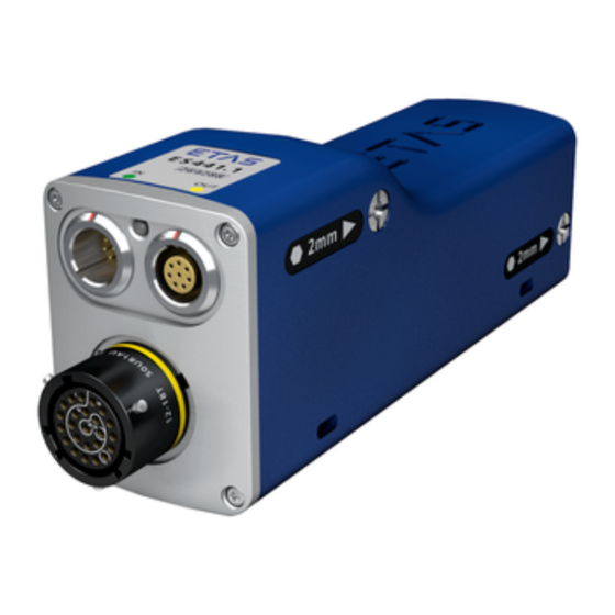
Data" on page 102. Housing A sturdy metal housing is used for the ES441.1; it has ports on the front of the device so it can fit into tight spaces. The ES441.1 is specifically designed to be installed in engine compartment, but also in the passenger cell. -
Page 18: Ports
Front 3.4.1 “Sensor” Port The front of the ES441.1 features a 22-pin Souriau port to which four sensors can be connected using a adapter cable. An individual sensor power supply port is available for each sensor. The use of a “cable tail” or “whip” solution with just one connector makes it possible to change the modules quickly within complex test setups. -
Page 19: Led
Functional State Display State yellow-red flashing Warning 0,5 s yellow reduced / Overload on a sensor supply 0,5 s red reduced voltage channel red illuminated Error during self-test fully bright red illuminated Internal error semi bright ES441.1 - User’s Guide... -
Page 20: Hardware Description
Features of the ES441.1 Fig. 4-1 ES441.1 Housing The ES441.1 Counter and Frequency Module with Sensor Supply is a member of the family of ES400-Modules. The ES441.1 can acquire digital signals at four input channels. There is a sensor supply for every channel For the complete technical data of the ES441.1, refer to the chapter "Technical... -
Page 21: Block Diagram
ETAS Hardware Description Block Diagram The ES441.1 is a module with four identical measurement channels, its own sen- sor supply for every measurement channel, two shared Ethernet interfaces and a power supply. FPGA Et hernet Connect or (Host direct ion) Et hernet . -
Page 22: Measurement Channels
Hardware Description ETAS Measurement Channels All measurement channels of the ES441.1 are identical. They consist of an input stage with signal acquisition and signal processing. The measurement channels are designed for input voltages of -50 V to +50 V. The minimum pulse width is limited to 120 ns. This limitation avoids the acquisi- tion of interfering pulses on the measurement channels. - Page 23 Measuring capabilities can be selected independently of one another for the measurement channels of the ES441.1. The measuring capabilities of the ES441.1 are described in chapter 5 on page 33. ES441.1 - User’s Guide...
-
Page 24: Sensor Supply
ETAS 4.3.2 Sensor Supply Every sensor that can be switched to the ES441.1 has an individual sensor supply voltage which can be set separately. The cable connected to the sensor port of the ES441.1 transfers both the sensor supply voltage and the sensor output voltage for the sensor. Additional cables or an additional external power supply for the sensor supply voltage are not required. -
Page 25: Data Transfer
Message Format “XCP on UDP” (Schematic) Using the UDP/IP standard for data transfer makes it possible to connect the modules directly to a PC, a router or a switch. In XCP communication, the PC has the master function. ES441.1 - User’s Guide... -
Page 26: Realization
The communication protocol used by the ES400 family makes it possible for third-party suppliers to use the communication protocol for their own, non- ETAS applications once the modules have been configured with the „ES4xx Configuration Tool from ES4xx_DRV_SW“ . 4.4.2... - Page 27 IEEE1588 (Precision Time Protocol). The modules add the time stamp to the Ethernet data package for every measure date. The combination of time stamp synchronization, full duplex and time slice proce- dure results in a very high reference data rate of the modules. ES441.1 - User’s Guide...
-
Page 28: Examples
4.4.3 Examples Example 1 Fig. 4-7 on page 28 shows an example of an application with three concatenated ES400 modules with the same acquisition rates. The transfer scheme for this configuration is shown in Fig. 4-8 on page 28. M ODUL 1 M ODUL 2 M ODUL 3 St ellgrößen... -
Page 29: Fig. 4-10 Transfer Scheme For Example 2 (Simplified, Not True To Scale)
Example 2 Fig. 4-9 on page 29 shows an example in which three modules with different acquisition rates are linked to each other. The transfer scheme for this configuration is shown in Fig. 4-10 on page 29. M ODUL 1 M ODUL 2 M ODUL 3 St ellgrößen... -
Page 30: Power Supply
Please contact our local experts to discuss your particular ES441.1 configura- tions. Example 1: For module chains which are equipped exclusively with ES410.1 or ES441.1, ETAS recommends the use of Y boost cables if the length of the module chain is longer than 10 modules. ES441.1 - User’s Guide... - Page 31 ETAS Example 2: For module chains which are equipped exclusively with ES411.1 or ES413.1 or ES421.1, ETAS recommends the use of Y boost cables if the length of the module chain • is longer than 16 modules (without sensor feeding) or •...
-
Page 32: Configuration
ETAS Configuration The configuration of the ES441.1 is performed entirely via the GUI within INCA. The configuration of the individual channels is saved either in INCA or in the individual ES400 modules. In the first case, you can prepare settings for specific measure tasks, e.g. -
Page 33: Functional Description
• "Measuring Sensor Signals" on page 33 • "Definitions" on page 35 • "Signal Sampling" on page 38 • "Overview of the Measuring Capabilities of the ES441.1" on page 39 • "Overflow" on page 39 • "Measuring Signal State" on page 40 •... - Page 34 Example: flow sensor, axle speed is not in proportion to the flow rate The signals measured and their adaptation enable the physical, technical and derived variables and measure values to be represented in the physical unit required. ES441.1 - User’s Guide...
-
Page 35: Definitions
ETAS Functional Description Definitions This section defines signals which are used in the description of the measuring capabilities of the ES441.1. Note All definitions in this section are definitions for digital signals. 5.2.1 Tab. 5-1 on page 35 shows all symbols used in the figures in the Functional Description chapter. -
Page 36: Pulse
If the period starts with an active-inactive edge, the period consists of a sequence of an inactive pulse with a subsequent active pulse. Input Period Signal Act ive Inact ive Time Fig. 5-3 Period, Starting with an Active-Inactive Edge ES441.1 - User’s Guide... -
Page 37: Cycle
Input Cycle Signal Act ive Inact ive Time Fig. 5-4 Cycle, Starting with an Inactive-Active Edge and n=3 Input Cycle Signal Act ive Inact ive Time Fig. 5-5 Cycle, Starting with an Active-Inactive Edge and n=3 ES441.1 - User’s Guide... -
Page 38: Signal Sampling
Signal Sampling 5.3.1 Sampling and Rates The sampling rate can be selected independently for every channel of the ES441.1 in fixed steps in the calibration software. The data is sampled synchro- nously at a fixed sampling rate. Input Signal Act ive... -
Page 39: Overview Of The Measuring Capabilities Of The Es441.1
ETAS Functional Description Overview of the Measuring Capabilities of the ES441.1 The ES441.1 module can acquire digital signals at the four input channels and evaluate these using various measuring capabilities: Measuring Capability Measure Signal State (signal state) State Event counting... -
Page 40: Measuring Signal State
Fig. 5-8 Measuring the Active and Inactive State (Fixed Measure Rate) Which input channels of the ES441.1 state should be measured on can be spec- ified in the calibration software. In the additional signal "stateCombined", the state of the four input channels at any one time is shown together in one byte. -
Page 41: Counter
(trigger channel) • Counter modes with parameters which can be configured with restrictions These measurement modes of the ES441.1 in its function as a counter can be divided into four groups: “Standard without Qualifying Signal” Counter Mode The signal at the measurement channel is counted regardless of signals at other measurement channels (see section 5.7.2 on page 42). -
Page 42: Standard Without Qualifying Signal" Counter Mode
The counter assigned to the measurement channel is configured as an up- counter. In this mode, the ES441.1 can count edges with the following measurement modes in accordance with the configuration in the calibration software: • Counting the edges when the input signal changes from inactive to active state •... -
Page 43: Fig. 5-10 Counting The Active-Inactive Edges
In the example in Fig. 5-11, the counter is reset at every sampling point. Counting Cycles Input Cycle Cycle Signal Act ive Inact ive Time Fig. 5-12 Counting Cycles The counter is reset at every sampling point. ES441.1 - User’s Guide... -
Page 44: Standard With Qualifying Signal" Counter Mode
In this mode, the ES441.1 can count edges with the following additional mea- surement modes: • Up-counter with measurement control (triggering) in acc. with –... -
Page 45: Fig. 5-13 Counting The Inactive-Active Edges With Resetting With The Inactive-Active Edge Of The Qualifying Channel
• Resetting the counter after every sampling point or • Resetting the counter with the edge of the qualifying channel selected in the calibration software or • Counter in Free Running Mode (no resetting). ES441.1 - User’s Guide... -
Page 46: Fig. 5-14 Counting The Inactive-Active Edges When The Qualifying Signal Is Active
Count Direction Control in acc. with the State of the Qualifying Signal In this counter mode, the ES441.1 is configured as an up-/down-counter with the count direction being controlled in acc. with the state at the assigned quali- fying channel (trigger channel). -
Page 47: Fig. 5-15 Counting The Inactive-Active Edges In "Up/Down1" Counter Mode
Qualif ying Signal Act ive Inact ive Time Fig. 5-15 Counting the Inactive-Active Edges in “Up/Down1” Counter Mode Input Signal Active Inactive Time Active Inactive Time Fig. 5-16 Counting the Inactive-Active Edges in “Up/Down3” Counter Mode ES441.1 - User’s Guide... -
Page 48: Up/Down" Counter Mode
Signal Act ive Inact ive Time Qualif ying Signal Act ive Inact ive Time Fig. 5-17 “Up/Down” Counter Mode When to use the “Up/Down” counter mode: • Acquisition of data from incremental transducers • Position determination ES441.1 - User’s Guide... -
Page 49: X1", "X2" And "X4" Counter Modes
Depending on the selected counter mode, the input signal of the qualifying channel is evaluated and measurement controlled at the assigned measurement channel. In this mode, the ES441.1 can count edges with the following additional mea- surement modes: Up-/down-counter with control of the count direction in acc. with •... -
Page 50: Fig. 5-18 X1 Counter Mode
ETAS “X1” Counter Mode In counter mode “X1”, the ES441.1 is configured as an up-/down-counter with the count direction being controlled by comparing the state of the signals at the measurement channel and the qualifying channel (trigger channel). The active- inactive edges are counted at the measurement channel: •... -
Page 51: Fig. 5-19 X2 Counter Mode
Functional Description “X2” Counter Mode In counter mode “X2”, the ES441.1 is configured as an up-/down-counter with the count direction being controlled by comparing the state of the signals at the measurement channel and the qualifying channel (trigger channel). The inactive- active and active-inactive edges are counted at the measurement channel: •... -
Page 52: Fig. 5-20 X4 Counter Mode
Functional Description ETAS “X4” Counter Mode In counter mode “X4”, the ES441.1 is configured as an up-/down-counter whose measurement channel and its assigned second channel are analyzed as equal channels. Both edges of the signals at the measurement channel and at the assigned second channel are evaluated according to different rules. - Page 53 • Greater resolution of the counter result • Greater accuracy of the counter result When to use the X4 counter mode: • Acquisition of data from incremental transducers (phase-shifted signals), • Position determination • Quadrature encoder/quadrature decoder for incremental transducers ES441.1 - User’s Guide...
-
Page 54: Time Measurement
5.8.1 Measurement Modes During time measurement, the ES441.1 always acquires the active time, the inac- tive time and the period duration of the signal at the measurement channel, regardless of the measure value selected in the calibration software. With these measure values, the signals can be determined completely in varying periods of time. - Page 55 Fig. 5-22 Measuring the Active Time of a Cycle Measuring the Active Time Between Two Sampling Points Input Signal Act ive Inact ive Act ive Time Time Fig. 5-23 Measuring the Active Time Between Two Sampling Points ES441.1 - User’s Guide...
- Page 56 The period duration is measured according to the selection of the period in the calibration software, i.e. whether the period is to begin with an inactive-active edge or with an active-inactive edge (see section 5.2.4 on page 36). ES441.1 - User’s Guide...
-
Page 57: Measurement Modes With A Qualifying Signal
"Measuring until the last current sampling point" is selected in the calibration software. With this assignment, the ES441.1 can determine active and inactive times using the additional measurement modes: • “Window1”: Measuring only takes place when the signal of the qualifying channel is active, •... -
Page 58: Frequency Measurement
With the frequency, determined on the basis of the measuring of the duration of the last cycle, and the number of periods per cycle, the ES441.1 can calculate the number of revolutions per minute (RPM) (see example in section 5.11 on page 65). -
Page 59: Measurement Modes With A Qualifying Signal
These measurement modes of the ES441.1 in the frequency function can be divided into four groups: •... -
Page 60: Fig. 5-29 Determination Of The Sign Of The Acquired Frequency Value When The Qualify
The state of the signal at the qualifying channel is evaluated. In the example (see Fig. 5-29 on page 60), the ES441.1 was configured in the calibration software in such a way that the sign of the determined frequency value is set to “+” when the signal of the qualifying channel is active. -
Page 61: Measuring The Duty Cycle
Measurement Accuracy Theoretical Error During Frequency Measurement The ES441.1 measures the period duration with the accuracy of the internal timebase of 20 ns. The frequency to be determined is calculated and corresponds to the reciprocal value of the period duration: f = 1 / T. - Page 62 ES441.1 are of comparable dimension. This is why, with high frequencies, the frequency should be deter- mined using the cycle duration and not the period duration.
-
Page 63: Timeout (Monitoring The Input Signal)
A check is carried out to see whether at least one signal change has taken place within this time. If there is no signal change, no new measure values can be determined. Depending on the measuring capability activated, the ES441.1 assigns fixed values to all sample values which follow in terms of time with the Timeout function. - Page 64 Example: Frequency Measurement around Zero If there is no change of the input signal after the expiry of a timeout in the mea- suring capability frequency measurement, the measure value is determined as being f = 0 Hz. ES441.1 - User’s Guide...
-
Page 65: Example
The configuration principle is demonstrated by the following simplified example. Fig. 5-32 16-2 "Speed Sensor" Wheel To be able to determine a speed with the ES441.1, a cycle has to be defined in the configuration software, for example: 1 revolution = 1 cycle = (16-2) periods The module always counts complete cycles. -
Page 66: Getting Started
CAUTION! Potential equalization in the vehicle over the shield of the Ethernet connecting cables of modules may occur! Mount the modules only to components with the same electrical potential or insulate the modules from the components. ES441.1 - User’s Guide... -
Page 67: Guarantee Of Features As Defined By Ip67
Fig. 6-1 Position of the Pressure Balance Element Standing liquids or liquids which do not flow away from the pressure balance element can permanently damage the membrane. The module then loses the features defined by IP67. ES441.1 - User’s Guide... -
Page 68: Assembly
(see Fig. 6-3 on page 68) on the right-hand side of the mod- ule. Fig. 6-4 Unscrewed Integrated Assembly Elements Openings for Cable Fasteners Every module base has two openings each on the right and left-hand side for attaching the modules to other components using cable fasteners. ES441.1 - User’s Guide... -
Page 69: Connecting Several Es400 Modules Mechanically
You can only successively screw additional modules, but not module blocks, onto the right-hand side of this module block. When creating module blocks, observe the defined order. ES441.1 - User’s Guide... - Page 70 Note Screw the two modules together without getting them off-thread! Both modules are now connected mechanically on one side. 3. Insert the Allen key into the other hexagon socket of the right-hand module. ES441.1 - User’s Guide...
-
Page 71: Attaching Es400 Modules To Other Components Using The Integrated
Here, you connect the ES400 module to the component using the integrated assembly elements. Screwing the two together works in the same way as con- necting several modules. Fig. 6-7 Attaching a Module to Other Components with the Integrated Assembly Elements ES441.1 - User’s Guide... - Page 72 Note Screw the two parts together without getting them off-thread! Both parts are now connected mechanically on one side. 5. Insert the Allen key into the other hexagon socket of the module. ES441.1 - User’s Guide...
- Page 73 To connect the ES400 module to other modules, you require a 2 mm Allen key (minimum length 20 mm). To connect to other modules: 1. Assemble other modules in accordance with the procedure described in the section 6.2.2 on page Fig. 6-8 Connecting to Other Modules ES441.1 - User’s Guide...
-
Page 74: Attaching Es400 Modules On Din Rails With The Integrated Assembly Elements
For this reason, the module must always be screwed onto the ES4xx angle bracket (left) from the right side. Additional modules can only be screwed onto the right side of this module, but not any module blocks. ES441.1 - User’s Guide... - Page 75 Connecting the ES400 module with additional modules requires a 2-mm hex key (minimum length 20 mm). Connecting with additional modules: 1. Connect additional modules according to the pro- cedure described in chapter 6.2.2 on page ES441.1 - User’s Guide...
-
Page 76: Attaching Es400 Modules To Other Components With Screws
You therefore have to screw the other component onto the module from the right. Once the module is screwed to the other component, you cannot screw any further modules to this one. ES441.1 - User’s Guide... - Page 77 5. Insert the other screw into the other hole in the component. 6. Screw the screw from the right-hand side of the component into the module. Note Screw the two parts together without getting them off-thread! Both parts are now completely connected mechan- ically. ES441.1 - User’s Guide...
-
Page 78: Attaching Es400 Modules On Din Rails Using Screws
1. Connect the module with additional modules (as required). 2. Connect the module with the ES4xx angle bracket (right). 3. Connect the ES4xx angle bracket with the DIN rail. Fig. 6-11 Fastening on DIN Rails with Additional Screws ES441.1 - User’s Guide... - Page 79 ES4xx angle bracket. Note Screw the two parts together without canting the threads! Both parts are now mechanically connected on one side. 5. Insert the other screw through the other bore of the ES4xx angle bracket (right). ES441.1 - User’s Guide...
- Page 80 DIN rail. 3. Engage the ES4xx angle bracket in the DIN rail by pressing on the ES4xx angle bracket or the module. The module connected with the ES4xx angle bracket is fastened to the DIN rail. ES441.1 - User’s Guide...
-
Page 81: Attaching Es400 Modules To Other Components Using Cable Fasten
DIN rail. 3. Engage the ES4xx angle bracket in the DIN rail by pressing on the ES4xx angle bracket or the module. The module connected with the ES4xx angle bracket is fastened to the DIN rail. ES441.1 - User’s Guide... -
Page 82: Drilling Template
Getting Started ETAS Drilling Template Fig. 6-13 Drilling Template ES441.1 - User’s Guide... -
Page 83: Applications
ES441.1 with additional ETAS Modules for MC Applications The ETAS Daisy Chain concept enables a simple network architecture since only the ES441.1 or the first module of the module chain is connected with the PC or with the "ETH" port of the ES59x.1. - Page 84 1 Type per Module Vehicle, Test Bench, Motor, ... Fig. 6-15 ES441.1 with ES910.3 and additional ETAS Modules for Rapid Proto- typing Applications The concept of the ES4xx/ES63x/ES93x product family to install the modules as close as possible to the sensors, the chain the modules with each other, and to connect only the first module of this chain with the ES910.3 or the RTPRO-PC,...
-
Page 85: Wiring Examples
ETAS Wiring Examples 6.5.1 ES400 Modules with additional ETAS Modules (Measurement and Calibration) Power Supply Daisy Chain Modules Power Supply ES595 ES411 ES413 ES420 ES430 ES410 ES415 ES421 ES432 ES441 Fig. 6-16 ES400 Modules with additional ETAS Modules (Measurement and... -
Page 86: Es400 Modules With Additional Etas Modules And Drive Recorder (Measurement And Calibration)
ETAS 6.5.2 ES400 Modules with additional ETAS Modules and Drive Recorder (Measurement and Calibration) Vehicle Drive Recorder 10/100 MBit/s Ethernet Power Supply Daisy Chain Modules Daisy Chain Measurement Modules ES411 ES413 ES420 ES59x ES410 ES415 ES421 ES441 Lambda Ambient /... -
Page 87: Es400 Modules With Es910.3 (Rapid Prototyping)
Power supply and Ethernet cable Daisy Chain CBEP430, modules CBEP4305 ETK connection cable CBM150 5, 6 CAN/LIN/FLX connection cable (CAN/LIN/FLX CBCFI100 combined) at ES910.3, at ES921.1 CAN connection cable (CAN only), at ES910.3, CBAC130, at ES921.1 CBAC140, CBAC150, CBCX130 ES441.1 - User’s Guide... -
Page 88: Es400 Modules With Es910.3 And Drive Recorder (Rapid Prototyping)
Function Order name Fig. 6-19 Ethernet adapter cable (100 Mbit/s) CBAE330 (con- nected to cable 2) Ethernet connection cable(1 Gbit/s) CBE230 (con- nected to cable 1) Power supply and Ethernet cable Daisy Chain CBEP430, modules CBEP4305 ES441.1 - User’s Guide... -
Page 89: Es400 Modules With Etas Rtpro-Pc (Rapid Prototyping)
ETAS 6.5.5 ES400 Modules with ETAS RTPRO-PC (Rapid Prototyping) Ethernet USB2 Power Supply Daisy Chain Modules ES581.4 ES411 ES413 ES420 ES430 ES410 ES415 ES421 ES432 ES441 Fig. 6-20 ES400 Modules with ETAS RTPRO-PC (Rapid Prototyping) Cable in Function Order name Fig. -
Page 90: Wiring
Accessories" on page 115. 6.6.1 “Sensor” Port To connect the sensors with the ES441.1, you can use different standard and adapter cables. Detailed information about the cables offered by ETAS is located in chapter "Cable for the Connection "Sensor"" on page 125. -
Page 91: Daisy Chain Ports ("In", "Out")
To wire the first module with the PC and the power supply 1. Connect the combined Ethernet and power supply cable to the “IN” port of the ES441.1. 2. Connect the RJ-45 connector to the free Ethernet interface port of your PC. - Page 92 2. Connect the combined Ethernet and power supply cable to the “OUT” port of the ES441.1 of the last module of the chain towards the PC. 3. Connect the combined Ethernet and power supply cable to the “IN”...
-
Page 93: Troubleshooting Problems
Please observe the LEDs which provide information on the functions of the inter- face and the ES441.1 (see the chapter "LED" on page 19) to be able to judge the operational state of the ES441.1 as well as troubleshooting measures. - Page 94 Daisy Chain modules on a PC card that supports the NDIS protocol. with multi-core processor? Are you using ES441.1 mod- Operate the ES441.1 modules at the ules common with other beginning of the module chain close to ES4xx modules? the host (PC, drive recorder).
- Page 95 Switch the module off and on again. Load the measuring configuration again. If the LED continues to show red, send the module to ETAS for repair. The firmware of Is the module to be updated Update the firmware of these ETAS...
-
Page 96: Problems And Solutions
Windows 7, 8.1 and 10 systems. Network security policies, however, may request the APIPA mechanism to be disabled. In this case, you cannot use a net- work adapter which is configured for DHCP to access ETAS hardware. The ETAS Network Manager displays a warning message. -
Page 97: Search For Ethernet Hardware Fails
If you use more than one PC or notebook for accessing the same ETAS hardware, the network adapters used must be configured to use the same logical network. If this is not possible, it is necessary to switch the ETAS hardware off and on again between different sessions (repowering). - Page 98 Select the Energy Management tab. Deactivate the Computer can switch off device to save energy option. 7. Select the Extended tab. 8. If the property Autosense is included, deactivate it. 9. Click OK to apply the settings. ES441.1 - User’s Guide...
-
Page 99: Personal Firewall Blocks Communication
Ethernet hardware at all, although the configuration parameters are correct. Some actions in ETAS products can lead to problems if the firewall is not properly parameterized, e.g. when opening the experiment environment in ASCET or for the hardware search by INCA or HSP. - Page 100 ETAS • Outgoing TCP/IP connections to the network configured for the ETAS application, destination ports 18001 to 18020 Note The ports to be used in a specific case depend on the hardware used. For more detailed information about the port numbers to be used, see the respective hardware documentation.
- Page 101 A correct operation of the product is not possible since the database file as well as various *.ini files are modified during the work. The ETAS software must be installed by an administrator in any case. It is recom- mended that the administrator ensures that the ETAS product or the processes are added to the list of selected exceptions of the Windows Firewall after the installation.
-
Page 102: Technical Data
Connection of sensor cable SN: 1234567 Serial number (seven-digit) Vx.y.z Hardware version of the product F 00K 123 456 Ordering number of the product, see chapter 10.1 on page 130 Operating voltage range (DC), Power consumption ES441.1 - User’s Guide... -
Page 103: Standards And Norms
In addition, the combination was tested by cascaded modules. ISO 16750-3, Sec. 4.2.2.2 Mech. shock 3 space axis, half sinus, Acceleration: 500 m/s², Shock duration: 6 ms, Shocks per direction and axis: 10, Units under test: active ES441.1 - User’s Guide... - Page 104 IPX7 Protection class test: Protection class IP67 (with cables con- nected) EN61000-4-2 Immunity ESD EN61000-4-3 Immunity radiated RF EN61000-4-4 Immunity EFT/B EN61000-4-5 Immunity surge EN61000-4-6 Immunity conducted RF DIN EN 55022 Emission radiation/ radio interference voltage ES441.1 - User’s Guide...
-
Page 105: Environmental Conditions
8.1.4 Maintenance the Product Do not open or change the module! Works on the module housing may be exe- cuted only by qualified technical personnel. Send defect modules to ETAS. 8.1.5 Cleaning the product We recommend to clean the product with a dry cloth. -
Page 106: Rohs Conformity
The user is obligated to separate the waste equipment and to provide it to the WEEE return system for reuse. The WEEE Directive applies to all ETAS devices, but not to external cables or bat- teries. Additional information about the recycling program of ETAS GmbH is available from the ETAS sales and service locations (see chapter 11 on page 133). -
Page 107: Declarable Substances
Some products from ETAS GmbH (e.g. modules, boards, cables) use components with substances that are subject to declaration in accordance with the REACH regulation (EU) no.1907/2006. Detailed information is located in the ETAS download center in the customer information "REACH Declaration" (www.etas.com/Reach). This information is continuously being updated. -
Page 108: Software
ETAS 8.7.2 Software To configure the ES441.1 and for control and data acquisition, you need soft- ware in the following versions: • INCA V6.2.0 with ES400 INCA Add-On V1.1.3 and higher • ES4xx Configuration Tool V1.1.3 and higher from ES4xx_DRV_SW (stand- alone operation) •... -
Page 109: Electrical Data
• "Sensor Power Supply" on page 110 • "Input Channels" on page 111 Note ETAS guarantees measurement accuracy of the ES441.1 for one year. Please use our calibration service (see section 4.9 on page 32)! Note Unless otherwise specified, all data applies at 25 °C. -
Page 110: Sensor Power Supply
Accuracy of the sensor supply voltage ±5 with 3 k load Resistance of sensor supply voltage outputs including CBAV411.1-2 cable Ripple voltage V (measurement lim- ited to 80 MHz) Max. voltage drift (temperature) +1.2 mV/K Output current Output current protection ES441.1 - User’s Guide... -
Page 111: Input Channels
0.1 s, 0.2 s, 0.5 s, 1 s, 2 s Maximum input voltage Input-to-input: 60 V DC / 30 V AC Input-to-ground of voltage supply or housing: 60 V DC / 30 V AC Input impedance > 2 M || < 250 pF ES441.1 - User’s Guide... -
Page 112: Pin Assignment
• "“IN” Connector" on page 112 • "“OUT” Connector" on page 113 • "“Sensor” Connector" on page 114 Note All connectors are shown with a view of the front of the ES441.1. All shields are at case potential. 8.9.1 “IN” Connector Fig. -
Page 113: Out" Connector
Operating voltage UBatt Operating voltage Ground Ground Received data, plus Send data, minus Received data, minus Ground Ground Send data, plus The following socket is mounted on "OUT" connector: LEMO 1B 8-pin A-coding (connection identified in yellow) ES441.1 - User’s Guide... -
Page 114: Sensor" Connector
Sensor channel 1, input - CH1 TEDS- Sensor channel 1, TEDS- CH2 TEDS- Sensor channel 2, TEDS- CH3 TEDS- Sensor channel 3, TEDS- CH4 TEDS- Sensor channel 4, TEDS- TEDS- Cable, TEDS- *): connected with operating voltage ground ES441.1 - User’s Guide... -
Page 115: Cables And Accessories
• "Cable for the Connection "Sensor"" on page 125 • "Protective Caps" on page 128 • "Angle Brackets" on page 129 Note Only use ETAS cables at the interfaces of the module. Adhere to the maximum cable lengths! ES441.1 - User’s Guide... -
Page 116: Combined Ethernet And Power Supply Cable
The connection to power outlets is not allowed! To prevent an inadvertent insertion in power outlets, ETAS recom- mends to equip the combined ethernet and power supply cables with safety banana plugs in areas with power outlets. -
Page 117: Cbep410.1 Cable
(MINI flat automotive fuse, quick-response, 3 A, 58 V). Robust, waterproof and dust-proof (IP67). Temperature rated for: -40 °C to +125 °C / -40 °F to +257 °F Product Length Order number CBEP4105.1-3 F 00K 110 026 ES441.1 - User’s Guide... -
Page 118: Cbep415.1 Cable
(MINI flat automotive fuse, quick-response, 3 A, 58 V). Robust, waterproof and dust-proof (IP67). Temperature rated for: -40 °C to +125 °C / -40 °F to +257 °F Product Length Order number CBEP4155.1-5 F 00K 110 027 ES441.1 - User’s Guide... -
Page 119: Cbep420.1 Cable
(MINI flat automotive fuse, quick-response, 3 A, 58 V). Robust, waterproof and dust-proof (IP67). Temperature rated for: -40 °C to +125 °C/ -40 °F to +257 °F Product Length Order number CBEP4205.1-3 F 00K 110 041 ES441.1 - User’s Guide... -
Page 120: Cbep425.1 Cable
(MINI flat automotive fuse, quick-response, 3 A, 58 V). Robust, waterproof and dust-proof (IP67). Temperature rated for: -40 °C to +125 °C / -40 °F to +257 °F Product Length Order number CBEP4255.1-3 F 00K 110 029 ES441.1 - User’s Guide... -
Page 121: Cbep430.1 Cable
(MINI flat automotive fuse, quick-response, 3 A, 58 V). Robust, waterproof and dust-proof (IP67). Temperature rated for: -40 °C to +125 °C / -40 °F to +257 °F Product Length Order number CBEP4305.1-0m5 0.5 m F 00K 110 030 ES441.1 - User’s Guide... -
Page 122: Ethernet Cable
(MINI flat automotive fuse, quick-response, 3 A, 58 V). Robust, waterproof and dust-proof (IP67). Temperature rated for: -40 °C to +125 °C / -40 °F to +257 °F Product Length Order number CBE401.1-0m5 0.5 m F 00K 106 128 ES441.1 - User’s Guide... -
Page 123: Cbe430.1 Cable
Robust, waterproof and dust-proof (IP67). Temperature rated for: -40 °C to +125 °C / -40 °F to +257 °F Product Length Order number CBE431.1-0m14 0.14 m F 00K 105 676 CBE431.1-0m30 0.30 m F 00K 105 685 ES441.1 - User’s Guide... -
Page 124: Cbex400.1 Cable
Product Length Order number CBEX400.1-3 F 00K 105 294 9.2.6 ES4xx_BRIDGE Fig. 9-16 ES4xx Bridge Ethernet bridge connecting blocked ES400 modules. Facilitates very compact measurement setups. IP67 compliant. Product Order number ES4xx_BRIDGE F 00K 105 684 ES441.1 - User’s Guide... -
Page 125: Cable For The Connection "Sensor
Temperature rated for: -40 °C to +125 °C Product Length Order number CBAV400.1-0m3 0.3 m F 00K 104 916 ES441.1 - User’s Guide... -
Page 126: Cbav411.1 Cable
You can customize the open connection of sensor cable CBAV411.1 and adapt it to the specific plug connector system of your measuring setup. Temperature rated for: -40 °C to +125 °C Product Length Order number CBAV411.1-2 F 00K 104 918 ES441.1 - User’s Guide... -
Page 127: Cbav413.1 Cable
Temperature rated for: -40 °C bis +125 °C Product Length Order number CBAV413.1-0m3 0.3 m F 00K 105 682 ES441.1 - User’s Guide... -
Page 128: Protective Caps
ETAS Protective Caps The connections "IN" and "OUT" of the ES441.1 can be protected with different protective caps according to the operating conditions. 9.4.1 Protective Caps supplied The "IN" and "OUT" ports of the ES4xx are covered with simple dust and trans- port caps on delivery. -
Page 129: Angle Brackets
Angle Bracket for mounting ES4xx modules to a DIN rail 35 x 7.5 (EN 60715 TH35). Stainless steel V2A. For mounting on right side of an ES4xx module. Product Order number Angle bracket right F 00K 107 176 ES441.1 - User’s Guide... -
Page 130: Ordering Information
(see chapter 10.2.1 on page 130). 10.2 Accessories 10.2.1 Cables Note If you require customized cables, please contact your ETAS contact partner or sales.de@etas.com. Cables for the connectors "IN" and "OUT" Ethernet cable: Order name Short name Order number Ethernet Chain Connection Cable, Lemo 1B CBE400.2-3... - Page 131 Cable, Lemo 1B FGL - Lemo 1B FGA - Banana (8fc-8mc-2mc), 0m5 Ethernet Chain Connection and Power Sup- CBEP4305.1- F 00K 110 030 ply Cable, Lemo 1B FGL - Lemo 1B FGA - Safety Banana (8fc-8mc-2mc), 0m5 ES441.1 - User’s Guide...
-
Page 132: Protective Caps
ES4xx Angle Bracket left ES4xx_AB_L F 00K 107 175 ES4xx Angle Bracket right ES4xx_AB_R F 00K 107 176 10.2.4 Device Calibration Order name Short name Order number Calibration Service for ES441.1 K_ES441 F 00K 105 802 ES441.1 - User’s Guide... -
Page 133: Etas Contact Addresses
Germany WWW: www.etas.com ETAS Subsidiaries and Technical Support For details of your local sales office as well as your local technical support team and product hotlines, take a look at the ETAS website: ETAS subsidiaries WWW: www.etas.com/en/contact.php ETAS technical support WWW: www.etas.com/en/hotlines.php... -
Page 134: Figures
Figures Fig. 3-1 Central and Decentral Sensor Cabling............15 Fig. 3-2 Front ......................18 Fig. 4-1 ES441.1 Housing ..................20 Fig. 4-2 Block Diagram .................... 21 Fig. 4-3 Input Stage....................22 Fig. 4-4 Definition of the Hysteresis for the Input Channel ........22 Fig. - Page 135 Openings for Cable Fasteners in ES400 Modules......... 81 Fig. 6-13 Drilling Template ..................82 Fig. 6-14 ES441.1 with additional ETAS Modules for MC Applications ....... 83 Fig. 6-15 ES441.1 with ES910.3 and additional ETAS Modules for Rapid Prototyping Applications....................84 Fig.
- Page 136 Connection „Sensor“ (one Cable Section)..........127 Fig. 9-22 Cap CAP_LEMO_1B.................. 128 Fig. 9-23 Cap CAP_LEMO_1B_LC ................128 Fig. 9-24 Cap CAP_SOURIAU_8STA................. 128 Fig. 9-25 Angle Bracket Left ..................129 Fig. 9-26 Angle Bracket Right .................. 129 ES441.1 - User’s Guide...
-
Page 137: Index
CBEP4255.1 120 CBEP430.1 121 CBEP4305.1 121 CBEX400.1 124 Cable fasteners 68 Cables 115 Calibration 32 Cap CAP_Lemo_1B 128 Cap CAP_Lemo_1B_LC 128 Cap CAP_SOURIAU_8STA 128 CE Declaration of Conformity 106 Communication protocols 25 Configurable hysteresis 22 Configuration 32 ES441.1 - User’s Guide... - Page 138 Input channels 111 Ports 18 Input stage 22 Potential differences 30 Input voltage Power supply 30 maximum 111 Power supply management 30 Interfering voltage filter 23 Presentation of information 9 Inverter 23 Product Exclusion of liability 10 ES441.1 - User’s Guide...
- Page 139 State 35 stateCombined 40 Supply voltage 109 Synchronization of the timebases 27 Synchronization, clock generator 27 System requirements 107 Time measurement 54 Time slice procedure 26 Time stamp 25 Timeout 63 Tool integration 32 Troubleshooting 93 ES441.1 - User’s Guide...
Need help?
Do you have a question about the ES441.1 and is the answer not in the manual?
Questions and answers