Table of Contents
Advertisement
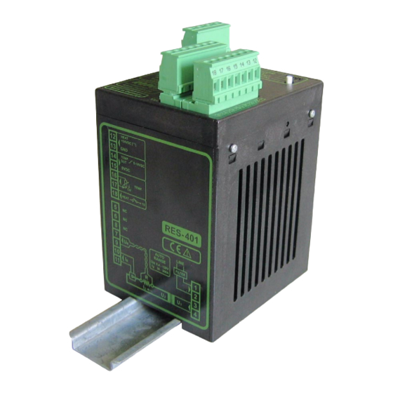
RESISTRON
RES-401
Operating
Instructions
Important features
•
Microprocessor technology
•
Automatic zero calibration (AUTOCAL)
•
Automatic optimization (AUTOTUNE)
•
Automatic configuration of the secondary voltage and current ranges
(AUTORANGE, as of October 2005)
•
Automatic frequency adjustment
•
Large current and voltage range
•
Set point selection with potentiometer
•
Temperature range: 300°C
•
0...10VDC analog output for ACTUAL temperature
•
Activated with contact or 24VDC signal
•
Alarm function
Industrie-Elektronik GmbH
Gansäcker 21
D-74321-Bietigheim-Bissingen (Germany)
GB
Tel: +49/(0)7142/7776-0
Fax: +49/(0)7142/7776-19
E-Mail:
info@ropex.de
Internet:
www.ropex.de
Data subject to change
Advertisement
Table of Contents

Related Manuals for Ropex RESISTRON RES-401


Summary of Contents for Ropex RESISTRON RES-401
- Page 1 Set point selection with potentiometer • Temperature range: 300°C • 0…10VDC analog output for ACTUAL temperature • Activated with contact or 24VDC signal • Alarm function Industrie-Elektronik GmbH Tel: +49/(0)7142/7776-0 E-Mail: info@ropex.de Gansäcker 21 Fax: +49/(0)7142/7776-19 Internet: www.ropex.de D-74321-Bietigheim-Bissingen (Germany) Data subject to change...
-
Page 2: Table Of Contents
Contents Safety and warning notes ....3 Controller functions ....19 Use . -
Page 3: Safety And Warning Notes
The resistance of the heatsealing band which is used must have a positive minimum Only the original ROPEX PEX-W2 or PEX-W3 temperature coefficient in order to guarantee current transformer may be used. Other trouble-free... -
Page 4: Line Filter
DIN EN 61010-1 Safety provisions for electrical (VDE 0411-1) measuring, control and laboratory The use of an original ROPEX line filter is mandatory in devices (low voltage directive). order to comply with the standards and provisions Overvoltage category III, pollution mentioned in section 1.7 "Standards / CE marking"... -
Page 5: Principle Of Operation
Principle of operation The use of RESISTRON temperature controllers • Increased machine capacity results in: • Extended life of the heatsealing bands and teflon coatings • Repeatable quality of the heatseals under any con- ditions • Simple operation and control of the sealing process Principle of operation The resistance of the heatsealing band, which is tem- to the required dynamic range despite the exceptionally... -
Page 6: Description Of The Controller
Description of the controller Description of the controller The microprocessor technology endows the RESIS- • Increased protection against dangerous conditions, such as overheating of the heatsealing band. TRON temperature controller RES-401 with previously unattainable capabilities: The ACTUAL temperature of the heatsealing band is supplied to an analog 0…10VDC output. -
Page 7: Modifications (Mods)
Designed according to VDE 0570/EN 61558 with a one section bobbin. Optimized for impulse operation with RESISTRON temperature controllers. Specified according to the heatsealing application ( ROPEX Application Report). Communication interface CI-USB-1 Interface for connecting a RESISTRON temperature controller with diagnostic inter- face (DIAG) to the PC (USB port). -
Page 8: Technical Data
Technical data Technical data Type of construction Housing for installation in the electrical cabinet Snaps onto a standard top hat rail (DIN TS35 rail, 35 mm) acc. to DIN EN 50022 Dimensions: 90 x 75mm; height: 135mm (incl. terminals) Line voltage All controllers manufactured as of October 2005: 115VAC version: 110VAC -15%…120VAC +10% (equivalent to 94…132VAC) 230VAC version: 220VAC -15%…240VAC +10% (equivalent to 187…264VAC) -
Page 9: Dimensions
Dimensions Installation If several controllers are installed on one top hat rail (DIN TS35 rail), a clearance of at least 20mm should be allowed between them. The moving clip required for fastening must be facing down for mounting on a horizontal top hat rail. -
Page 10: Installation
12, Installation procedure section 8.6 "Wiring diagram" on page 14 and the ROPEX Application Report. The information pro- Proceed as follows to install the RESISTRON tempera- vided in section 8.2 "Installation steps" on page 11 ture controller RES-401: must also be heeded additionally. -
Page 11: Installation Steps
Installation Installation steps Use heatseal bands with suitable temperature coefficient Heatseal element push-on with coppered ends connectors Heatsealing band R= f (T) No additional Connect U measuring resistance wires directly to in secondary Note heatsealing band ends circuit number Sufficient wire of turns Twisted cross-section... -
Page 12: Power Supply
The filter type and size must be determined according to FILTER the load, the transformer and the machine wiring ROPEX Application Report). Short wires Do not run the filter supply wires (line side) parallel to the filter output wires (load side). -
Page 13: Line Filter
CE mark. The wiring instructions contained in section 8.3 "Power ROPEX line filters are specially optimized for use in supply" on page 12 must be observed. RESISTRON control loops. Providing that they are Large cross-section wire to ground max. -
Page 14: Wiring Diagram
Installation Wiring diagram Line filter LF-xx480 NOTE: RES-401 AUTOCAL button LINE also provided on controller START (HEAT) with 24VDC signal prim. Impuls GND 13 transformer Ground for 24VDC signals. sec. Must be grounded externally to prevent electrostatic Heat- charging! sealing band (Internal ground) twisted... -
Page 15: Startup And Operation
You can find the exact configuration of the function (AUTOCAL). The voltage is configured in the DIP switches in the ROPEX Application range from 0.4VAC to 120VAC and the current in the Report calculated for your particular application. -
Page 16: Replacing And "Burning In" The Heatsealing Band
If the secondary current I is less than 30A, the PEX-W2 or PEX-W3 current transformer must have two turns ( ROPEX Application Report). 8.10 Replacing and "burning in" the resistance of the heatsealing band is reduced by appro- ximately 2…3%. However, this at first glance slight... -
Page 17: Startup Procedure
2005, the settings of the DIP switches on the up (up to September 2005: Twin-color LED blinks controller are indicated in the ROPEX Application red and green alternately) the duration of the cali- Report and depend on the heatsealing band that is bration process (approx. - Page 18 In this case the controller configuration is incorrect ( section 8.9 "Controller configuration" The controller is now on page 15 and ROPEX Application Report). ready Repeat the calibration after the controller has been configured correctly. 9. When the zero point has been calibrated suc- 8.11.2 Restart after replacing the heat-...
-
Page 19: Controller Functions
AUTOCAL process. RESISTRON RES- 401 Temperature Button for manual activation of AUTOCAL controller function (zero calibration). Do not press ROPEX unless heatsealing band is cold. Tel:+49(0)7142-7776-0 Made in Germany Manufactured up to September 2005 AUTOCAL AUTOCAL Button for manual activation of AUTOCAL function (zero calibration). - Page 20 Controller functions In addition to the functions shown in the diagram by the LEDs. These states are described in detail in the above, various controller operating states are indicated table below: As of October 2005: Blinks slowly (1Hz) Blinks fast (4Hz) Lit continuously RESET active, AUTOCAL requested, but...
-
Page 21: Temperature Setting
External grounding is not allowed. If this warning is ignored, the con- troller will be damaged by frame currents. If a ROPEX PD-3 precision potentiometer is used, the SET temperature can be adjusted exactly with the help Voltage values: of the digital display in the window of the dial. -
Page 22: Automatic Zero Calibration (Autocal)
The yellow LED on the front panel lights up when the The characteristics of the ROPEX ATR-3 temperature AUTOCAL function is active (up to September 2005: indicator (size, scaling, dynamic response) are ideally Twin-color LED blinks red/green alternately). The suited to this application and this instrument should the- actual value output (terminals 14+15) is 0…3°C (corre-... -
Page 23: Start" Signal (Heat)
Controller functions AUTOCAL function is not executed (as of October 2005: "HEAT" LED lit). • By means of a control contact at terminals 15+18 4. If the controller has already operated correctly - at least once - after starting up, the "AUTOCAL" func- max. -
Page 24: Diagnostic Interface/Visualization Software (As Of October 2005)
An alarm can only be reset by switching the controller off and then on again. The ROPEX visualization software is described in a separate document. Error messages The RESISTRON temperature controller RES-401 indi- cates faults only by means of the LED. -
Page 25: Maintenance
Line filter LF- . . 480 06: Continuous current 6A, 480VAC, Art. No. 885500 35: Continuous current 35A, 480VAC, Art. No. 885506 Impulse transformer See ROPEX Application Report for design and ordering information Communiction interface CI-USB-1 Art. No. 885650 Potentiometer PD- 3: For 300°C range, Art. No. 881103 Scope of supply: Potentiometer with digital dial Temp. -
Page 26: Index
Index Index Line frequency Line voltage Accessories Actual value output Alarm output Alloy Maintenance Ambient temperature Modifications Analog temperature meter MODs Application Application Report AUTOCAL Overheating of heatsealing band Automatic zero calibration AUTOTUNE PEX-W2/-W3 PEX-W3 Burning in the heatsealing band Potentiometer Power dissipation Power supply...
Need help?
Do you have a question about the RESISTRON RES-401 and is the answer not in the manual?
Questions and answers