Table of Contents
Advertisement
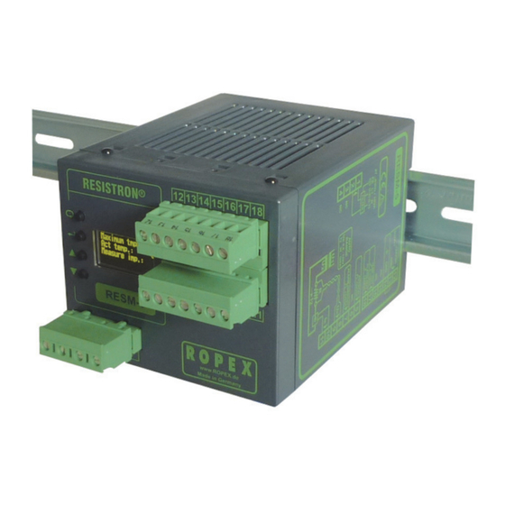
RESISTRON
RES-5010
Operating
Instructions
Important features
•
Microprocessor technology
•
OLED display (yellow / green), 4 lines, 20 characters (multilingual)
•
Automatic zero calibration (AUTOCAL)
•
Automatic configuration of the secondary voltage and current ranges (AUTORANGE)
•
Diagnostic interface for the PC visualization software
•
Automatic frequency adjustment
•
Heatsealing band alloy and temperature range selectable
•
Configurable alarm output
•
Configurable RESET input
•
0...10VDC analog output for ACTUAL temperature, electrically isolated
•
24VDC control inputs for AUTOCAL and ALARM-IN/RESET, electrically isolated
•
Alarm function with error diagnosis
Functionally compatible with the RESM-4
Industrie-Elektronik GmbH
Adolf-Heim-Str. 4
74321-Bietigheim-Bissingen (Germany)
Tel.: +49 7142 7776-0
Fax: +49 7142 7776-211
E-Mail:
info@ropex.de
Internet:
www.ropex.de
Data subject to change
Advertisement
Table of Contents

Related Manuals for Ropex RESISTRON RES-5010


Summary of Contents for Ropex RESISTRON RES-5010
- Page 1 24VDC control inputs for AUTOCAL and ALARM-IN/RESET, electrically isolated • Alarm function with error diagnosis Functionally compatible with the RESM-4 Industrie-Elektronik GmbH Tel.: +49 7142 7776-0 E-Mail: info@ropex.de Adolf-Heim-Str. 4 Fax: +49 7142 7776-211 Internet: www.ropex.de 74321-Bietigheim-Bissingen (Germany) Data subject to change...
-
Page 2: Table Of Contents
Contents Safety and warning notes ....3 Unit functions ..... . . 22 Use . -
Page 3: Safety And Warning Notes
The resistance of the heatsealing band which is used must have a positive minimum Only the original ROPEX PEX-W2 or PEX-W3 temperature coefficient in order to guarantee current transformer may be used. Other trouble-free... -
Page 4: Line Filter
The CE marking on the controller confirms that the device itself complies with the above-mentioned standards. The use of an original ROPEX line filter is mandatory in It does not imply, however, that the overall system also order to comply with the standards and provisions fulfils these standards. -
Page 5: Basics Of Temperature Control / Measurement
Basics of temperature control / measurement (any RESISTRON controller in the "400" or "5000" while the current transformer signal I is supplied by a series with an alarm output); it measures the resistance separate current transformer. of the heatsealing band and indicates the temperature A variable limit function is used to monitor the maximum in parallel operation using a separate current temperature;... -
Page 6: Basics
Basics of temperature control / measurement resistance value for each temperature based on its detached or corroded clamps, worn copper plating) alloy-specific (temperature coefficient simply leads to a harmless reduction in the actual resistance). heatsealing band temperature, a partial short-circuit This value may be altered by external impacts such as (ground fault, conductive foreign particles, physical partial short-circuits, contacting problems, changed... -
Page 7: Fault Causes
Basics of temperature control / measurement Fault causes If the actual temperature of a heatsealing band in a closed control loop deviates from the set point, the following relationship is true: If all of the components belonging to the control loop are analyzed with respect to possible faults that could ΔR ΔT... -
Page 8: Measures To Reduce The Risk Of Overheating
Use short cables where possible • Copper the ends at least 10 mm into the bar • Use only plug connectors that conform to ROPEX • Protect the coppered ends with a layer of nickel or specifications ("Basics" documentation) gold if there is a risk of corrosion •... -
Page 9: Possible Faults And How To Detect Them
Basics of temperature control / measurement Possible faults and how to detect them Detected with RESISTRON Additional Additional, controller monitoring redundant Possible fault ("400" or "500" current RESISTRON series) with alarm transformer monitoring device output RESM-5 Heatsealing band break and U measurement cables (break or short circuit) Contact between two heatsealing bands (wired... -
Page 10: Residual Risks
Basics of temperature control / measurement Residual risks → makes poor contact (loose contact) contact resistance. Even if the RESISTRON monitoring device RESM-5 The sealing tool is open, the heatsealing band is cold, and the controller is calibrated using the (and the optional monitoring current transformer MSW) AUTOCAL function. -
Page 11: Accessories And Modifications
Accessories and modifications Accessories and modifications Accessories A wide range of compatible accessories and peripheral devices are available for the RESISTRON monitoring device RESM-5. They allow it to be optimally adapted • The products described below are only a few of the to your specific heatsealing application as well as to wide range of accessories available for RESIS- TRON monitoring devices ("Accessories"... -
Page 12: Technical Data
Power supply system Balanced TN or TT system, max. 415VAC Installation category III Operation in potential-free systems (e.g. an IT system) is only permitted after consultation with ROPEX. Line frequency 50 / 60Hz (47…63Hz, automatic adjustment to frequencies in this range) -
Page 13: Dimensions
Dimensions Installation A minimum safety clearance of 20mm all round (e.g. from other devices and wiring) must be allowed when installing the controller. The moving clip required for fastening must be facing down for mounting on a horizontal top hat rail. End holders to mechanically fix the controller must be fitted at both ends for mounting on a vertical top hat rail. -
Page 14: Installation
7.3 "Wiring diagram" on page 17, and warranty provisions. section 7.3 "Wiring diagram" on page 17, and the ROPEX Application Report. The information provided in section 7.2 "Installation steps" on Installation procedure page 15 must also be heeded. -
Page 15: Installation Steps
PLC / machine control evaluation of alarms system enable both the status and the sequence of the (recommended by ROPEX) alarms to be evaluated (e.g. an alarm indicated by the The RESISTRON monitoring device RESM-5 is a... - Page 16 RESISTRON controllers with separate evaluation alarms (loop-through mode) of alarms (recommended by ROPEX)" on page 15). On The RESISTRON monitoring device RESM-5 has a the other hand, it is very difficult to reconstruct the control input for evaluating the alarms of the main alarm sequence.
-
Page 17: Wiring Diagram
Installation Wiring diagram Line filter LF-xx480 RESM-5 LINE AUTOCAL with 24VDC signal ALARM-IN/RESET with 24VDC signal prim. Impulse transformer Ground Must be grounded sec. externally to pre- vent electrostatic charging! Heat- sealing Twisted band Auxiliary power supply (Internal ground) +24VDC NO EXTERNAL GROUNDING ALLOWED! -
Page 18: Power Supply
8.4.1 "Initial startup" on page 20 to start up the must be laid twice through the PEX-W2 or PEX-W3 unit for the first time. current transformer ( ROPEX Application Report). 8.2.1 Configuration of the secondary voltage and current ranges... - Page 19 Startup and operation 8.2.2 Menu language You can choose between 200°C, 300°C (factory setting), 400°C, and 500°C. The menu language can be changed while the RESISTRON monitoring device is operating. You set it 8.2.6 Configuration the maximum with step 201 in the Configuration menu. The following temperature (alarm threshold) settings are possible: English, German...
-
Page 20: Heatsealing Band
Startup and operation Heatsealing band situations, refer to the risk analysis for the machine or plant. 8.3.1 General Each time the heatsealing band is replaced, the zero The heatsealing band is a key component in the control point must be calibrated with the AUTOCAL function loop because it is both a heating element and a sensor. - Page 21 RESM-5 configuration is incorrect Then return to ( section 8.2 "Unit configuration" on page 18 and step 3 ROPEX Application Report). Repeat the zero point Error message with error code Error diagnosis calibration after the unit has been configured 101…103, 107, 108,...
-
Page 22: Basic Functional Test On The Resm-5
(refer to the risk analysis for the machine or plant). To prevent dangerous situations, refer to the information provided in the ROPEX Applica- 5. Activate the START signal on the temperature cont- tion Report and the risk analysis for the machine or roller. -
Page 23: Display
Unit functions Display RESM-5. This message also includes details of the software version. 9.2.1 Power-up message A power-up message appears on the display for approximately 2 seconds when you switch on the Company name Software ID number Unit type (RESM-5) 9.2.2 Display in home position perature is shown as a digital value and the ACTUAL... -
Page 24: Navigation In The Menus
Unit functions 9.2.4 Error message on the display in the form of an error message ( section 9.17 "System monitoring / alarm output" on The RESM-5's error diagnostics function is always page 36). active. If an error is detected, it is immediately indicated Error message Error description and code... - Page 25 Unit functions 9.3.2 Navigation when an alarm is run the "AUTOCAL" function by pressing "ENTER" ( section 9.8 "Automatic zero calibration indicated (AUTOCAL)" on page 32). If an alarm is indicated, the RESM-5 shows the Alarm If you press the "MENU" key for longer than 2s in the menu.
-
Page 26: Menu Structure
Unit functions Menu structure Settings Configuration Power-up message Home position Language Factory settings 101 Heatsealing temp. Alloy Preheat temp. 204 Temp. coefficient Starting delay 205 Temperature range 104 Heatsealing time 206 Max. temperature Cooling value 207 Set point reached Hold mode 208 Set point exceeded Autocal? Time control... - Page 27 Unit functions Configuration Continued from previous page Heatup timeout 220 Meas. imp. length Autocomp "Output 1" 225 Temperature unit System time Visualization Screensaver RESET input Back to home position RESM-5 Page 27...
-
Page 28: Menu Steps
"ENTER" key ( section 10 "Factory settings" on page 43). You can use the "UP" and "DOWN" keys to determine whether • The RESM-5 should be reset to the ROPEX factory settings • The current configuration should be specified as the default setting •... - Page 29 Unit functions Name Description Setting range Temperature range Various temperature ranges can be selected here. 200°C The temperature range setting permits the RESM-5 300°C to be adjusted to the required operating range. It 400°C also determines the scale that is used for the 500°C progress bar and the analog output.
- Page 30 Unit functions Name Description Setting range Screensaver To extend the life of the OLED display, you can 0 (=off)…20min specify the time here after which it is dimmed. If you set "0min", the display is not dimmed. The display lights up again as soon as a key is pressed, an alarm occurs, or an input signal is activated.
-
Page 31: Monitoring Temperature Setting (Maximum Temperature Set Point)
Unit functions Monitoring temperature setting signal, which is proportional to the real ACTUAL tem- perature, at terminals 17+14. (maximum temperature set point) You can set the maximum temperature on the RESM-5 RESISTRON monitoring device RESM-5 with menu step 206. Act. value max. -
Page 32: Automatic Zero Calibration (Autocal)
By selecting step 107 in the Settings menu and heatsealing band. pressing the "ENTER" key The characteristics of the ROPEX ATR-x temperature You can activate this function by selecting step 107 in meter (size, scaling, dynamic response) are ideally the Settings menu and then pressing the "ENTER" key. -
Page 33: Alarm-In/Reset" Signal
Unit functions successfully, error message appears • An error message is reset if one is present (Note: The error message is not reset until the ( section 9.18 "Error messages" on page 37). "ALARM-IN/RESET" signal is deactivated) You should always wait for the heatsealing 24VDC band and the bar to cool down (to ambient RESM-5... -
Page 34: Temperature Unit
Unit functions option via the external AUTOCAL input (terminals You can still display all steps, values, and 5+14). parameters even if the Configuration menu is The following settings are possible: disabled. However, you are no longer allowed to enter or change any values. 1. -
Page 35: Display Brightness
Unit functions Rotary coding switch (as of August 2014) Schalter- Configuration menu position Unlocked Locked SWITCH POS. CONFIGURATION MENU Unlocked Locked 0 = Factory settings 9.14 Undervoltage detection The Configuration menu is not disabled as default ("0" position). If you set the rotary coding switch to "5", the Configuration menu is disabled and you cannot Trouble-free operation of the RESISTRON monitoring make any changes there. -
Page 36: Diagnostic Interface / Visualization
"ENTER" telephone cable) could damage the unit and result key again or at the latest after 30s. in malfunctions. The ROPEX visualization software is described in a separate document. 9.17 System monitoring / alarm output To increase operational safety and avoid faulty 9.16... -
Page 37: Error Messages
( section 9.18 "Error messages" on The error codes described below can also be displayed page 37). using ROPEX visualization software If a state that requires AUTOCAL occurs – or if the unit ( section 9.16 "Diagnostic interface / visualization configuration is not correct –... - Page 38 Unit functions Part 1 of 3: Error messages (faults) NOTE: The error messages shown here are output as faults (a constant error voltage appears at the actual value output; the alarm output is energized). Act. val. Action if machine Error output Action if machine Cause...
- Page 39 Unit functions Part 1 of 3: Error messages (faults) NOTE: The error messages shown here are output as faults (a constant error voltage appears at the actual value output; the alarm output is energized). Act. val. Action if machine Error output Action if machine Cause...
- Page 40 Unit functions Part 2 of 3: Error messages (warnings) NOTE: The specified error messages are initially output as warnings (actual value output jumps back and forth between two values; alarm output is de-energized). When the "START" signal on the temperature controller is activated, the warning changes to a fault (actual value output no longer jumps back and forth, see bold italic values;...
-
Page 41: Fault Areas And Causes
Unit functions Part 3 of 3: Error messages (warnings) NOTE: The specified error messages are initially output as warnings (actual value output jumps back and forth between two values; alarm output is de-energized). When the "START" signal on the temperature controller is activated, the warning changes to a fault (actual value output no longer jumps back and forth, see bold italic values;... - Page 42 Unit functions Fault area Explanation Possible causes Load circuit interrupted after U - Wire break, heatsealing band break - Contact to heatsealing band is defective pickoff point PEX-W2 / W3 current transformer measurement cable from current transformer interrupted signal interrupted - Wire break, triac in controller defective Primary circuit interrupted - Primary winding of impulse transformer interrupted...
-
Page 43: Factory Settings
Factory settings Factory settings The RESISTRON monitoring device RESM-5 is configured at the factory as follows: Settings menu Step 107 AUTOCAL temperature: 20°C Configuration menu Step 201 Language: German This selection is NOT changed if the factory settings are restored with step 202 in the Configuration menu. Step 204 Temp. -
Page 44: Customer Settings
202 in the Configuration menu. You can store asked to confirm the new settings (safety query). customer settings in addition to the Ropex settings: If you confirm these settings by pressing the "ENTER" The following settings are possible: key for approximately 2seconds, you then see another 1. -
Page 45: How To Order
How to order How to order RESM - 5/ . . . V AC 115: Power supply 115VAC, Art. No. 885241 230: Power supply 230VAC, Art. No. 885242 400: Power supply 400VAC, Art. No. 885243 Scope of supply: Unit includes connector plug-in parts (current transformer must be ordered separately) Modification MOD . -
Page 46: Index
Index Index Accessories Line filter Actual value output Line frequency Alarm output Line voltage "ALARM-IN" signal Alloy Ambient temperature Maintenance Analog input "MAN" key locked Analog output Maximum temperature set point Analog temperature meter Measurement cable Application Measuring range Application Report Modifications AUTOCAL MODs... - Page 47 Index Wiring diagram Wiring RESM-5 Page 47...
Need help?
Do you have a question about the RESISTRON RES-5010 and is the answer not in the manual?
Questions and answers