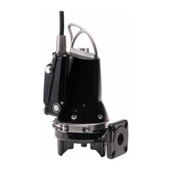
Grundfos SEG AUTOAdapt Service Instructions Manual
Hide thumbs
Also See for SEG AUTOAdapt:
- Installation and operating instructions manual (60 pages) ,
- Instructions manual (52 pages) ,
- Instruction manual (40 pages)

Related Manuals for Grundfos SEG AUTOAdapt


Summary of Contents for Grundfos SEG AUTOAdapt
- Page 1 GRUNDFOS INSTRUCTIONS SEG AUTO Adapt 0.9 - 4.0 kW, DIN, 50 Hz Service instructions...
-
Page 2: Table Of Contents
English (GB) Service instructions Original service instructions 1. Symbols used in this document CONTENTS DANGER Indicates a hazardous situation which, if not avoided, Page will result in death or serious personal injury. Symbols used in this document Returning the product for service Servicing pumps with explosion-proof motors WARNING Indicates a hazardous situation which, if not avoided,... -
Page 3: Returning The Product For Service
CAUTION 2.1 Servicing pumps with explosion-proof motors Electric shock Service work on Ex pumps must be carried out by Grundfos or a Minor or moderate personal injury workshop authorised by Grundfos. Violation of this requirement - It must be possible to lock the mains switch in will invalidate the Ex classification of the pump. -
Page 4: Identification
4. Identification 4.2 Type key The type key covers the entire Grundfos SEG AUTO range ADAPT 4.1 Nameplate of wastewater pumps. This is why the type key has a number of empty fields for the grinder pumps. Each SEG grinder pump is identified by means of the type key below. -
Page 5: Approvals
5. Approvals 5.1 Approval standards All versions have been approved by LGA (Notified body under the Construction Products Directive) according to EN 12050-1. 5.2 Explanation to the Ex approval The explosion-proof version has been approved by DEKRA according to the ATEX directive. The explosion protection classification of the SEG AUTO pump is Europe CE 0344 ADAPT... -
Page 6: Installation Types
6. Installation types 6.2 Free-standing submerged installation Pumps for free-standing submerged installation can stand freely 6.1 Installation on auto-coupling on the bottom of the pit or similar location. Pumps for permanent installation can be mounted on a stationary auto-coupling guide rail system or a hookup auto-coupling system. -
Page 7: Storing And Handling The Product
7. Storing and handling the product The pump can be transported in a vertical or horizontal position. Make sure that it cannot roll or fall over. 7.1 Storing the product During long periods of storage, protect the pump against moisture and heat. -
Page 8: Torques And Lubricants
8. Torques and lubricants 0.9 to 1.5 kW 2.6 to 4.0 kW Torque Pos. Description Quantity Lubricant Dimensions Dimensions [Nm] 5 x 5 x 12 Rocol Sapphire O-ring D32.0 x 4 D32.0 x 4 Rocol Sapphire O-ring D164.5 x 3 D204.0 x 3 Rocol Sapphire O-rings... -
Page 9: Service Tools
Puller for shaft seal Bearing heater Inductor heater 9.2 Special tools 9.3 Tightness test tools Designation Description Part No Grundfos PC Tool PC Tool link USB 97655366 Test plug M48 x 1.5 - 6G Test plug M12 x 20 Special tools Pos. -
Page 10: Servicing The Product
All service work must be carried out by specially trained staff. 3000 operating hours. The number of operating hours can be read by means of a CIU XX2 and a Grundfos GO remote control. Before carrying out service, make sure that the pump has been thoroughly flushed with clean water. -
Page 11: Checking The Shaft Seal
4. Check the oil for impurities. This gives a good indication of the - Death or serious personal injury condition of the shaft seal. See section 10.4 Checking the - The cable must only be replaced by Grundfos or shaft seal. an authorized service workshop. -
Page 12: Dismantling And Assembling The Product
11. Dismantling and assembling the product General information Position numbers of parts (digits) refer to section Drawings. Position numbers of tools (letters) refer to section 9. Service tools. Before dismantling the product • Switch off the power supply. • Close the isolating valves, if fitted, to avoid draining the piping system. -
Page 13: Assembling The Product
Bearings of explosion-proof products must only be 5. Check the condition of the shaft where the secondary seal of replaced by Grundfos or a service workshop the shaft seal touches the shaft. The bush (103) fitted to the authorised by Grundfos. - Page 14 6. Fit the oil chamber (155) with bearing (153) on the rotor/shaft (172). Fit the punch (F) on the inner ring and tighten gently. See fig. 13. Fig. 14 Shaft seal assembly, 0.9 - 1.5 kW Pos. Description Lubricate with soapy water only. Fig.
-
Page 15: Electronic Unit
11.2.3 Fitting the impeller 11.3 Electronic unit 11.3.1 Opening the electronic unit CAUTION 1. Clean the pump around the electronic unit to protect the Sharp element electronic parts from dirt when opening the electronic unit. Minor or moderate personal injury 2. -
Page 16: Replacing The Run Capacitor, Single-Phase Pumps
10. Grab the leads on each side of the connector and pull a little 11.3.2 Replacing the electronic unit to check the joints. 1. See section 11.3.1 Opening the electronic unit 11. Carefully pull the new insulating sheath over the joints and fix 2. -
Page 17: Replacing The Cable Plug
Dismantling the level sensor Maintenance and service work on explosion-proof 1. Open the electronic unit. See section 11.3.1 Opening the pump must be carried out by Grundfos or a service electronic unit. workshop authorised by Grundfos. 2. Remove the sensor wire from the PC board. -
Page 18: Testing The Sensors
12.3.1 Dry-running sensor (dry test) 1. Place the pump in horizontal position. 2. Connect Grundfos PC Tool to the pump. 3. Connect the pump to the power supply, but do not start it yet. Make sure that the pump base is clear from objects. -
Page 19: Drawings
13. Drawings 13.1 Sectional drawing, 0.9 to 1.5 kW Single-phase pump only... -
Page 20: Exploded View, 0.9 To 1.5 Kw
13.2 Exploded view, 0.9 to 1.5 kW... -
Page 21: Sectional Drawing, 2.6 To 4.0 Kw
13.3 Sectional drawing, 2.6 to 4.0 kW... -
Page 22: Exploded View, 2.6 To 4.0 Kw
13.4 Exploded view, 2.6 to 4.0 kW Fig. 21 SEG AUTO , 2.6 - 4 kW ADAPT... -
Page 23: Material Specification
13.5 Material specification Pos. Description Material EN standard AISI/ASTM Stainless steel Rivet Stainless steel Stainless steel O-ring O-ring O-rings Grinder ring Stainless steel 1.4542 Grinder head Stainless steel 1.4542 Stator Terminal board Impeller Cast iron EN-JL-1030 Pump housing Cast iron EN-JL-1030 Stator housing Cast iron... - Page 24 Pos. Description Material EN standard AISI/ASTM Dry-running sensors** 1.4404 285a O-ring 285b Set screw Level sensor 1.4404 287b O-ring 287c Set screw 288c Pt1000 sensor Silica gel Paint Two-component epoxy * Single-phase pumps only. ** Explosion-proof pumps have two dry-running sensors. Subject to alterations.
- Page 25 BOMBAS GRUNDFOS DO BRASIL Turkey Siu Wai Industrial Centre GRUNDFOS Pumper A/S Av. Humberto de Alencar Castelo Branco, GRUNDFOS POMPA San. ve Tic. Ltd. Sti. 29-33 Wing Hong Street & Strømsveien 344 Gebze Organize Sanayi Bölgesi CEP 09850 - 300...
- Page 26 97727298 0917 ECM: 1207911 www.grundfos.com...
Need help?
Do you have a question about the SEG AUTOAdapt and is the answer not in the manual?
Questions and answers