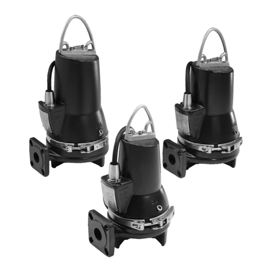
Grundfos SEG Series Instructions Manual
2.0 - 5.5 hp -60 hz
Hide thumbs
Also See for SEG Series:
- Installation and operating instructions manual (40 pages) ,
- Instructions manual (38 pages) ,
- Wiring diagrams (2 pages)

Related Manuals for Grundfos SEG Series


Summary of Contents for Grundfos SEG Series
- Page 1 GRUNDFOS INSTRUCTIONS 2.0 - 5.5 hp ~ 60 Hz Installation and operating instructions...
-
Page 2: Table Of Contents
1. Limited warranty Products manufactured by GRUNDFOS PUMPS CORPORATION CONTENTS (Grundfos) are warranted to the original user only to be free of defects in material and workmanship for a period of 24 months Page from date of installation, but not more than 30 months from date Limited warranty of manufacture. -
Page 3: Symbols Used In This Document
Clamp SEG pumps are used in pressurized systems, e.g. in hilly areas. Pump foot The pumps can be controlled via the Grundfos control box with Pump housing motor-protective circuit breaker. See installation and operating instructions for the selected unit. -
Page 4: Operating Conditions
3.3 Operating conditions 4. Delivery and handling The Grundfos SEG range are designed for intermittent operation The pump may be transported and stored in a vertical or (S3). When completely submerged, the pumps can also run horizontal position. Make sure that it cannot roll or fall over. -
Page 5: Identification
Rated current, Δ Rated voltage, Δ Rated current, Y Cos φ, 1/1 load Rated voltage, Y Starting capacitor [µF] Net weight [lbs] Run capacitor [µF] Insulation class Frequency [Hz] Production country Electrical safety* Grundfos logo Approvals * For USA and Canada... -
Page 6: Type Key
5.2 Type key The type key covers the entire Grundfos SEG range of wastewater pumps. This is why the type key has a number of empty fields for the grinder pumps. Each SEG grinder pump is identified by means of the type key below. Please note that not all combination options are available. -
Page 7: Approvals
For safety reasons, all work in pits must be supervised by a 6. Approvals person outside the pump pit. The standard versions of SEG 60 Hz pumps have been approved by CSA and the explosion-proof version holds a CSA and FM It is advisable to make all maintenance and service Note Note... -
Page 8: Potentially Explosive Environments
302 °F (150 °C) and must guarantee the disconnection of the We recommend that you always use Grundfos power supply; the power supply must be reset Caution accessories to avoid malfunctions due to incorrect manually. -
Page 9: Submerged Installation On Auto-Coupling
8.1 Submerged installation on auto-coupling 8.2 Free-standing submerged installation Pumps for permanent installation can be mounted on a stationary Pumps for free-standing submerged installation can stand freely auto-coupling guide rail system. on the bottom of the pit or the like. See fig. on page 20. -
Page 10: Electrical Connection
Float switches used in potentially explosive environments must be approved for this application. They must be connected to the Grundfos SLC, DLC controller via the intrinsically safe LC-Ex4 barrier to ensure a safe circuit. -
Page 11: Wiring Diagrams
9.1 Wiring diagrams 9.2 Start and stop levels The difference in level between start and stop can be adjusted by means of the installed level detecting equipment. 275 °F (135 °C) and Note 257 °F (125 °C) Note Both the two following points must be observed. below apply to •... -
Page 12: Pump Controllers
10. Start-up Controllers incorporating motor protection relay and control unit Warning are available from Grundfos: Before starting work on the pump, make sure that the When installing the level switches, observe the following points: fuses have been removed or the mains switch has •... -
Page 13: Operating Modes
10.2 Operating modes 10.3 Direction of rotation The pumps are designed for intermittent operation (S3). When The pump may be started for a very short period completely submerged, the pumps can also run continuously Note Note without being submerged to check the direction of (S1). -
Page 14: Maintenance And Service
The table states the quantity of oil in the oil chamber of SEG Warning pumps: Except for service on the pump parts, all other service work must be carried out by Grundfos or a Oil in oil chamber Pump type service workshop authorized by Grundfos. -
Page 15: Checking The Shaft Seal
11.3 Checking the shaft seal Assembly of grinder system: 1. Fit the grinder head (45). The dogs on the back of the grinder Check the oil to make sure that the shaft seal is intact. head must engage with the impeller holes (49). If the oil is greyish white like milk or contains a large quantity of 2. -
Page 16: Service Kits
If you request Grundfos to service the pump, contact Grundfos with details about the pumped liquid, etc. before returning the pump for service. Otherwise Grundfos can refuse to accept the pump for service. -
Page 17: Fault Finding
12. Fault finding Warning All regulations applying to pumps installed in potentially explosive environments must be observed. Make sure that no work is carried out in potentially explosive atmosphere. Warning Before attempting to diagnose any fault, make sure that the fuses have been removed or the mains switch has been switched off. -
Page 18: Technical Data
This product or parts of it must be disposed of in an environmentally sound way: 1. Use the public or private waste collection service. 2. If this is not possible, contact the nearest Grundfos company or service workshop. Subject to alterations. - Page 19 Appendix Dimensional drawings One-pump installation on auto coupling Fig. 1...
- Page 20 Free-standing installation Fig. 2...
- Page 21 Dimensions Power [hp (kW)] Inch 18.98 3.94 9.92 1 1/2" 6.06 2.87 4.84 5.28 3.94 (1 phase) DN40 (1.5) Inch 18.39 3.94 1 1/2" 6.06 4.84 5.28 3.94 (3 phase) DN40 SEG.A15 (1.5) Inch 20.51 3.94 11.5 4.68 1 1/2" 6.81 8.46 2.36...
- Page 22 Weights Power Weight [hp (kW)] [lb (kg)] 2.0 (1 phase) (1.5) 101.4 (46) 2.0 (3 phase) (1.5) 101.4 (46) SEG.A15 3.0 (2.6) 101.4 (46) 4.0 and 5.5 (3.1 and 4.0) 178.6 (81) 3.0 (2.6) 101.4 (46) SEG.A20 4.0 and 5.5 (3.1 and 4.0) 178.6 (81) Pos.
- Page 23 Sectional drawings 188a 188a 153a 153b 105a 105a 173a 112a 150a 193a 188a 188a 188a 188a 188a SEG, 2.0 hp (1.5 kW) Fig. 3...
- Page 24 SEG L, 2.0 Hp (1.5 kW) Fig. 4...
- Page 25 188a 153a 153b 188a 112a 173a 150a 193a 188a 188a 188a 188a SEG, 3.0 - 5.5 Hp (2.6 - 4.0 kW) Fig. 5...
- Page 26 Appendix Schémas d'encombrement Installation pompe unique sur accouplement automatique Fig. 1...
- Page 27 Installation autonome Fig. 2...
- Page 28 Tables de dimensions Puissance [CV (kW)] Pouces 18.98 3.94 9.92 1 1/2" 6.06 2.87 4.84 5.28 (1 phase) DN40 (1.5) Pouces 18.39 3.94 1 1/2" 6.06 4.84 5.28 (3 phases) DN40 SEG.A15 (1.5) Pouces 20.51 3.94 11.5 4.68 1 1/2" 6.81 8.46 2.36...
- Page 29 Table de poids Puissance Poids [CV (kW)] [lb (kg)] 2.0 (1 phase) 101.4 (46) (1.5) 2.0 (3 phases) (1.5) 101.4 (46) SEG.A15 3.0 (2.6) 101.4 (46) 4.0 and 5.5 (3.1 and 4.0) 178.6 (81) 3.0 (2.6) 101.4 (46) SEG.A20 4.0 and 5.5 (3.1 and 4.0) 178.6 (81) Pos.
- Page 30 Dessins en coupe 188a 188a 153a 153b 105a 105a 173a 112a 150a 193a 188a 188a 188a 188a 188a SEG, 2.0 CV (1.5 kW) Fig. 3...
- Page 31 SEG L - pompe, 2.0 CV (1.5 kW) Fig. 4...
- Page 32 188a 153a 188a 153b 112a 173a 150a 193a 188a 188a 188a 188a SEG, 3.0 à 5.5 CV (2.6 à 4.0 kW) Fig. 5...
- Page 33 Appendix Planos dimensionales Instalación compuesta por una bomba con acoplamiento automático Fig. 1...
- Page 34 Instalación en posición libre Fig. 2...
- Page 35 Tablas de dimensiones Potencia [hp (kW)] 18.98 3.94 9.92 1 1/2" 6.06 2.87 4.84 5.28 3.94 (monofásica) DN40 (1.5) 18.39 3.94 1 1/2" 6.06 4.84 5.28 3.94 (trifásica) DN40 SEG.A15 (1.5) 20.51 3.94 11.5 4.68 1 1/2" 6.81 8.46 2.36 5.63 5.27 3.94...
- Page 36 Tabla de peso Potencia Peso [hp (kW)] [lb (kg)] 2.0 (monofásica) (1.5) 101.4 (46) 2.0 (trifásica) (1.5) 101.4 (46) SEG.A15 3.0 (2.6) 101.4 (46) 4.0 and 5.5 (3.1 and 4.0) 178.6 (81) 3.0 (2.6) 101.4 (46) SEG.A20 4.0 and 5.5 (3.1 and 4.0) 178.6 (81) Pos.
- Page 37 Planos seccionales 188a 188a 153a 153b 105a 105a 173a 112a 150a 193a 188a 188a 188a 188a 188a SEG, 2.0 hp (1.5 kW) Fig. 3...
- Page 38 SEG L, 2.0 hp (1.5 kW) Fig. 4...
- Page 39 188a 153a 188a 153b 112a 173a 150a 193a 188a 188a 188a 188a SEG, 3.0 a 5.5 hp (2.6 a 4.0 kW) Fig. 5...
- Page 40 Phone: +1-905 829 9533 C.P. 66600 Apodaca, N.L. México Phone: +1-630-236-5500 Telefax: +1-905 829 9512 Phone: +52-81-8144 4000 Fax: +1-630-236-5511 Telefax: +52-81-8144 4010 www.grundfos.ca GRUNDFOS Kansas City www.grundfos.mx 17100 West 118th Terrace Olathe, KS 66061 Phone: +1-913 227 3400 Fax: +1-913 227 3500...
- Page 42 98449106 0216 ECM: 1169529 www.grundfos.com www.grundfos.us...
Need help?
Do you have a question about the SEG Series and is the answer not in the manual?
Questions and answers