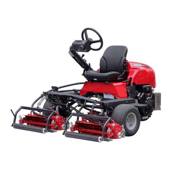
Baroness LM315GC Owner's Operating Manual
Riding greens mower (diesel model)
Hide thumbs
Also See for LM315GC:
- Service manual (199 pages) ,
- Owner's operating manual (115 pages) ,
- Assembly and installation manual (20 pages)

Related Manuals for Baroness LM315GC


Summary of Contents for Baroness LM315GC
- Page 1 Riding Greens Mower (Diesel Model) Owner's Operating Manual Serial No. LM315GC:31648- "Required reading" Read this manual before using the machine. Original Instructions Ver.4.0...
- Page 2 LM315GC Regulations California Proposition 65 California Spark Arrester (For California, USA) (For California, USA) Warning WARNING: Operation of this equipment may create Operating, servicing and maintaining sparks that can start fires around dry a passenger vehicle or off-road vegetation. vehicle can expose you to chemicals A spark arrester may be required.
- Page 3 LM315GC Greeting Thank you for purchasing the Baroness product. This manual describes the proper handling, adjustment, and inspection of your product. We hope you will use the product safely, and take advantage of its best performance. Keeping The Owner's Operating...
- Page 4 The operator is responsible for operating the product properly and safely. Maintenance service for this machine should be performed by a mechanic with expertise. If you have any questions concerning maintenance or genuine parts, please contact a Baroness dealer or Kyoeisha.
- Page 5 When replacing parts, be sure to use genuine Baroness parts or parts designated by Kyoeisha. Note that the Baroness product warranty may not apply to defects caused by the use of parts from other companies. Prior to use, carefully read the following manuals to thoroughly understand the contents for safe and correct operation.
- Page 6 LM315GC Introduction...
-
Page 7: Table Of Contents
LM315GC Contents Safety .............. Page 1-1 Safe Operating Practices .......Page 1-2 Disposal ............Page 2-1 Recycle and Waste Disposal ......Page 2-2 Product Overview .......... Page 3-1 Specifications ..........Page 3-2 Names of Each Section ......... Page 3-5 Regulation Decals ..........Page 3-5 Safety Signs and Instruction Signs .... - Page 8 LM315GC Contents...
-
Page 9: Safety
LM315GC Safety Safe Operating Practices ...... Page 1-2 Training ..........Page 1-2 Preparation ..........Page 1-2 Operation ..........Page 1-3 Maintenance .......... Page 1-4 Storage ..........Page 1-5 Page 1-1... -
Page 10: Safe Operating Practices
LM315GC Safety Failure to adequately follow these safety Never allow children or people unfamiliar precautions may cause an accident resulting in with these instructions to use or service the injury or death. machine. Local regulations may restrict the age of the... -
Page 11: Operation
LM315GC Safety Add fuel before starting the engine. Never operate while people, especially Never remove the cap of the fuel tank or children, or pets are nearby. add fuel while the engine is running or Only operate in good light, keeping away when the engine is hot. -
Page 12: Maintenance
LM315GC Safety Do the following before leaving the Implement the following work before operator's position. adjusting, cleaning or repairing. Stop on level ground. Stop the machine on level ground. Disengage the all drives. Disengage drive to the cutting unit(s). Set the parking brake. -
Page 13: Storage
LM315GC Safety When checking the hydraulic circuit for Swallowing engine coolant can cause injury pinhole leaks or oil leakage from nozzles, do or death; keep out of reach from children and not use your hands. pets. Use items such as paper or corrugated cardboard to find leakage points. - Page 14 LM315GC Safety Page 1-6 Safe Operating Practices...
-
Page 15: Disposal
LM315GC Disposal Recycle and Waste Disposal ....Page 2-2 About Recycle ........Page 2-2 About Waste Disposal ......Page 2-2 Page 2-1... -
Page 16: Recycle And Waste Disposal
LM315GC Disposal Recycle and Waste Disposal About Recycle Recycling battery etc. is recommended for environmental conservation and economical use of resources. It may be required by local laws. About Waste Disposal Make sure that waste generated when servicing or repairing the machine is disposed of in accordance with local regulations. -
Page 17: Product Overview
LM315GC Product Overview Specifications ........Page 3-2 Specifications .........Page 3-2 Sound Pressure Level ......Page 3-4 Sound Power Level ....... Page 3-4 Vibration Level ........Page 3-4 Carbon Dioxide (CO2) Emissions ..Page 3-4 Names of Each Section ......Page 3-5 Regulation Decals ........Page 3-5... -
Page 18: Specifications
LM315GC Product Overview Specifications Specifications Model LM315GC Name Riding Greens Mower Type for greens for tees for fields Total length 215 cm 84.65 in ← ← ← ← Total width 203 cm 79.92 in ← ← ← ← Dimensions Steering 132 - 141 51.97 -... - Page 19 LM315GC Product Overview 1.5 - 18.0 0.059 - 6.0 - 20.0 0.236 - 10.0 - 40.0 0.394 - Operating height (Mowing height) 0.709 in 0.787 in 1.575 in Number of Blades 9, 11 ← HST 2WD [3WD Traveling ← ←...
-
Page 20: Sound Pressure Level
LM315GC Product Overview Sound Pressure Level Sound Pressure Level This machine was confirmed to have a continuous A-weighted sound pressure level of 87 dB by measuring identical machines in accordance with the procedure specified in ISO 5395-1:2013. Sound Power Level... -
Page 21: Names Of Each Section
LM315GC Product Overview Names of Each Section Regulation Decals Positions of Regulation Decals H,I,J quwxcl-124 Names of Each Section_001 1CE31229 Operation panel Positions of Regulation Decals_001 Steering wheel Serial number plate Seat Specification decal Underseat cover UKCA mark Mower pedal... -
Page 22: Description Of Regulation Decals
LM315GC Product Overview Description of Regulation Decals UKCA Mark Serial Number Plate (For UK) UKCA mark indicates that the machine sold in The serial number plate indicates the model the UK complies with the UK requirements. and serial number of the machine. - Page 23 LM315GC Product Overview ROPS Compliance Decal Recycle Decal The ROPS compliance decal indicates the Recycle Decal illustrates Recycle Mark in manufacturer, model, etc., in accordance with accordance with local regulation. International Standard ISO 21299:2009. (For Europe) c3td3e-003 y7wov5-001 ROPS Compliance Decal_001...
-
Page 24: Safety Signs And Instruction Signs
For more information go to Order them from a Baroness dealer or www.P65Warnings.ca.gov/passenger-vehicle. K4205002140 Kyoeisha. -
Page 25: Positions Of Safety Decals And Instruction Decals
LM315GC Product Overview Positions of Safety Decals and Instruction Description of Safety Decals and Decals Instruction Decals D Operation Decal LM315GC0504B0 Decal D, operation Warning Read the Owner's Operating Manual. Warning Apply the parking brake, stop the engine, and then remove the ignition key before leaving the machine. - Page 26 LM315GC Product Overview Caution to Mutilation Decal Hydraulic Oil Icon K4205001600 K4209000980 DECAL, CAUTION TO MUTILATION Hydraulic oil icon Read the Owner's Operating Manual. Warning May cut your hand or leg - Stop the cutter rotation and engine. Otherwise you may get injured.
- Page 27 LM315GC Product Overview Caution for High Temperatures Decal Caution Slope Decal K4205001920 K4205002040 Decal, caution for high temperatures Decal, caution slope Caution Caution High temperature - Do not touch. Otherwise, Rollover - Do not work on slopes of 15 you will get burned.
- Page 28 LM315GC Product Overview Caution for Slopes (3WD) Decal Caution to Noise Decal K4205002080 K4205002090 Decal, caution for slopes (3WD) Decal, caution to noise (3WD spec model only) Warning Rollover - Do not switch between 2WD and 3WD while traveling on downward slopes.
-
Page 29: Handling Instructions
LM315GC Handling Instructions Inspections ..........Page 4-3 Procedure to Start/Stop Engine ..Page 4-26 Reel Cutter (Cutting Cylinder) and Start/Stop of Engine ......Page 4-26 Bed Knife (Bottom Blade) ...... Page 4-3 Safety Mechanisms ......Page 4-28 Cover ............. Page 4-3 Warning Mechanisms ...... - Page 30 LM315GC Handling Instructions Transporting Procedure ....... Page 4-44 Storage ..........Page 4-44 Before Long-Term Storage ....Page 4-44 Page 4-2...
-
Page 31: Inspections
LM315GC Handling Instructions Cover Inspections Inspection of Covers Inspect the machine according to the maintenance schedule so that you will be able to Warning take advantage of its optimum performance for a long period of time. If you have removed the covers during... -
Page 32: Dustproof Net
LM315GC Handling Instructions Dustproof Net Cleaning of Radiator Inspection of Dust-Proof Mesh Important Make sure that there is no damage to the An unclean radiator cover may cause dust-proof mesh. overheating or damage to the engine. Make sure that the dust-proof mesh is not It may also cause malfunction of the hydraulic contaminated. -
Page 33: Coolant
LM315GC Handling Instructions Coolant Caution The radiator cap is pressurized. Inspection of Coolant If you remove the radiator cap while the engine is overheated, hot steam will burst out, Caution possibly resulting in burns. Do not touch the radiator or coolant during... -
Page 34: Hydraulic Oil
LM315GC Handling Instructions Open the reserve tank cap, and then Important supply clean water up to the "FULL" mark. Use Shell Tellus S2M46 (or equivalent) as hydraulic oil. In case of an equivalent, consult Characteristics of Hydraulic Oil and use hydraulic oil whose characteristics are superior to those of the specific hydraulic oil. -
Page 35: Hydraulic Hoses
LM315GC Handling Instructions Start the engine, raise and lower the mower Air Cleaner units, and turn the steering wheel left and right. Inspection of Air Cleaner Move forward and reverse repeatedly The air cleaner is a component that removes several times. -
Page 36: Battery
LM315GC Handling Instructions Replace the air cleaner cap, and then fix it Make sure that the battery fluid level is securely with the clips. between the UPPER LEVEL (maximum fluid level line) and the LOWER LEVEL (minimum fluid level line). -
Page 37: Electrical Wiring
LM315GC Handling Instructions Electrical Wiring Supply of Battery Fluid Inspection of Electrical Wiring Danger Danger Be careful not to let your skin, eyes or clothes, Important etc., come into contact with the battery fluid or Electrical short circuit will cause fire, electrical accidentally swallow the fluid. -
Page 38: Belt
LM315GC Handling Instructions Belt Engine Oil Inspection of Belt Inspection of Engine Oil Warning Important The engine must be stopped when the belt is Securely tighten the oil level gauge and oil inspected. filler cap. Stop the engine, wait for 10 to 20 minutes... -
Page 39: Fuel
LM315GC Handling Instructions Fuel Supply of Engine Oil For details on handling the engine, please Inspection of Fuel Quantity refer to the separate Engine Handling Manual. With the machine on a level surface, observe Important the fuel gauge on the fuel tank to check the fuel level. - Page 40 LM315GC Handling Instructions Fuel Supply Air Bleeding of Fuel System Warning Important Supply fuel before starting the engine. Be sure to tighten the air-bleeding plug except Never remove the tank cap or supply fuel when air bleeding. while the engine is running.
-
Page 41: Fuel Filter
LM315GC Handling Instructions Make sure that the traveling pedal is Grass Catcher neutral. Inspection of Grass Catcher Set the ignition key to "START" position. Important The grass catcher may no longer correctly collect grass clippings due to its wear, In the case that there are still air bubbles in damage, deformation, etc., caused by... -
Page 42: Tightening Torques
LM315GC Handling Instructions Tightening Torques Important Refer to the Tightening Torque table. Note that the Baroness product warranty may not apply to defects caused by incorrect or overtorque tightening, etc. Standard Tightening Torques Bolts and Nuts Important A number of bolts are used in each part of this machine. - Page 43 LM315GC Handling Instructions General bolt Strength classification 4.8 Nominal diameter tib3yb-001 kgf-cm lb-in 3 - 5 30.59 - 50.99 26.55 - 44.26 7 - 9 71.38 - 91.77 61.96 - 79.66 14 - 19 142.76 - 193.74 123.91 - 168.17 29 - 38 295.71 - 387.49...
- Page 44 LM315GC Handling Instructions Hydraulic Hose The tightening torques for union joints and union adaptors with parallel pipe threads (G, PF) are shown in the table below. A union joint or adaptor will not become loose or leak as long as it is tightened by the specified torque.
-
Page 45: Principal Tightening Torques
LM315GC Handling Instructions Principal Tightening Torques Tightening Torque by Model LM315GC Tighten the following bolts and nuts at the torque specified in the table. For thread locking adhesive, apply a middle strength thread locker (ThreeBond 1322 or equivalent anaerobic sealant). - Page 46 LM315GC Handling Instructions Tightening torque Thread Location Code Part name locking kgf-cm lb-in adhesive Reel shaft LM315GB2102Z0 Reel gear fixing nut 25.49 22.13 Reel shaft (with LM315GB2101Z0 20-tooth reel gear 25.49 22.13 Groomer) Bed knife Screw, heat-treated 71.38 – 61.96...
-
Page 47: Adjustment Before Work
LM315GC Handling Instructions Adjustment before Work Adjustment of Seat Use the seat adjustment levers to adjust the seat. Adjust the position according to the operator's body size. Important After adjustment of the seat, make sure that bs3d75-001 the backrest does not interfere with the hood Adjustment of Armrest_001 with the operator seated. -
Page 48: Adjustment Of Blade Engagement
LM315GC Handling Instructions Adjustment of Blade Engagement Caution When handling the reel cutter (cutting cylinder) or bed knife (bottom blade), wear gloves to protect your hands. Pay attention not to let the reel cutter (cutting cylinder) catch your gloves. Otherwise, you may injure your hand or fingers. -
Page 49: Adjustment Of Cutting Height
Adjust the cutting height to fit your cutting work. adjustment: Perform back lapping. Adjustment of Rear Roller LM315GC (for greensmowing) You can adjust the rear roller by six stages. Attach the rear roller in a position that suits your work requirements within the cutting height range. - Page 50 LM315GC Handling Instructions LM315GC (for tee mowing) LM315GC (for field mowing) You can adjust the rear roller by eight You can adjust the rear roller by eight stages. stages. Attach the rear roller in a position that Attach the rear roller in a position that...
- Page 51 LM315GC Handling Instructions Adjustment of Front Roller Bed knife (bottom blade) Cutting height setting screw Set the slide caliper to the required cutting Cutting height gauge height, adjust the neck position of the Cutting height cutting height setting screw of the cutting...
- Page 52 LM315GC Handling Instructions Front groomer Cutting height Groomer setting screw Cutting height gauge Cutting height gauge Cutting height setting screw Front roller Operating height Front roller Rear roller Loosen the nuts fixing the right and left Bed knife (bottom blade) groomer adjustment bolts.
- Page 53 LM315GC Handling Instructions Cutting Height and Blade Thickness of Bed Knife (Bottom Blade) Important The recommended minimum cutting heights are based on those of common greens. They may vary according to the green conditions and machine specifications. If the green undulation is hard, set it a little bit higher in order not to damage the green surface.
-
Page 54: Procedure To Start/Stop Engine
LM315GC Handling Instructions Important Starter operation must take 15 seconds or less. If the engine does not start, stop using the battery for 30 to 60 seconds to avoid exhausting the battery. Open the fuel cock. The fuel cock is located beneath the fuel tank. - Page 55 LM315GC Handling Instructions Shift the throttle lever halfway from the Important "Low speed" to the "High speed" position. Quickly returning the ignition key from the Important "START" position to the "ON" position may The thermo-start lamp turns off at the result in damage to the machine.
-
Page 56: Operation Method
LM315GC Handling Instructions Safety Mechanisms Caution Never park the machine on a slope. This machine features a safety device for starting/stopping the engine. Park the machine on level ground. As for starting the engine, the safety device Apply the parking brake. -
Page 57: Description Of Operation Decals
LM315GC Handling Instructions Reel rotation/stop mark Low speed Engine rotation mark High speed Mower unit Up/Down decal Mower Unit Up/Down Decal Key switch mark K4203001520 Mower unit up-switch (with reel excess Decal, lifting units discharge system) mark This indicates up-down of the mower unit. - Page 58 LM315GC Handling Instructions Mower Unit Up-Switch (with Reel Excess Light Switch Mark Discharge System) Mark Note: Mower unit up-switch (with reel excess Depending on the specifications, this function discharge system) mark may not be available. This indicates mower unit up-switch and reel K4203001610 excess discharge system.
-
Page 59: Light Switch
LM315GC Handling Instructions BACKWARD Decal Mower Unit Reel Rotation Changeover Decal K4203001440 K4203001550 Decal, BACKWARD Sticker, rotating direction This indicates backward travel. This indicates changeover of normal rotation, neutral and reverse rotation of mower unit reel cutter. BACKWARD kqca3e-002 BACKWARD Decal_001... -
Page 60: Throttle Lever
LM315GC Handling Instructions Throttle Lever Mower Pedal The throttle lever is located in the operation Caution panel and enables you to adjust the engine rpm. Do not keep depressing the mower pedal after Move the throttle lever toward the "High speed"... -
Page 61: Joystick
LM315GC Handling Instructions Joystick Mower Unit Up Switch Note: Up Switch (with Reel Excess Discharge System) Depending on the specifications, this function may not be available. Warning Important The reel cutter rotates while holding down the up switch when the reel rotation switch is set Even if the reel rotation switch is set to the to the "Rotation"... -
Page 62: 2Wd/3Wd Selector Switch
LM315GC Handling Instructions Reel excess discharge system ・ Important Reel excess discharge system is the function to remove clippings inside the reel When switching between 2WD and 3WD cutter by rotating the reel cutter with the up operation, make sure to stop the machine switch on the condition that the mower unit completely. -
Page 63: Reel Rotation Switch
LM315GC Handling Instructions When the reel rotation switch is set to the Reel Rotation Switch "Rotation" position, the reel cutters (cutting cylinders) will rotate or stop in sync with the up Warning and down motion of the mower units. When the... -
Page 64: Transmission Selector Lever
Traveling Pedal Important Caution For the LM315GC (for fields), normally cut When the machine is traveling at a high with the lever set to the "Low speed" position. speed, it will not stop immediately after you take your foot off the traveling pedal. -
Page 65: Parking Brake Lever
LM315GC Handling Instructions Hood Forward pedal Reverse pedal Caution Parking Brake Lever Do not open the hood in strong winds. Caution Caution Never park the machine on a slope. Be careful not to pinch your fingers when you open or close the hood. -
Page 66: Underseat Cover
LM315GC Handling Instructions Rotate the lock lever 90 degrees clockwise Underseat Cover to fix the underseat cover. Caution Be careful not to pinch your fingers when you open or close the underseat cover. Front Remove the grass catcher located at the center. -
Page 67: Instruments
LM315GC Handling Instructions Swisher Holder Hour Meter Note: The hour meter indicates the accumulated Depending on the specifications, this function operation time of the engine. may not be available. The number in red figures on a white Swisher pole can be stored in this holder for background is incremented every thirty-six transport. -
Page 68: Water Temperature Gauge
LM315GC Handling Instructions Water Temperature Gauge Pilot Lamps The water temperature gauge is located in the Charge Lamp operation panel. The charge lamp is the left pilot lamp located This instrument indicates the water in the operation panel. temperature inside the engine. -
Page 69: Move
LM315GC Handling Instructions Move Thermo-start lamp Oil Pressure Lamp Traveling Procedure The oil pressure lamp is the right pilot lamp Warning located in the operation panel. It turns on when the ignition key is set to the Set the reel rotation switch to the "Stop"... -
Page 70: Cutting Work
LM315GC Handling Instructions Tow the machine slowly. Towing The Machine Cutting Work If the machine does not travel due to engine trouble, etc., you can move it in the following Cutting Work ways: ・ Pushing by hand Warning Towing (See the following instruction.) ・... -
Page 71: Reel Excess Discharge System
LM315GC Handling Instructions Start the work following the procedure below. Preventing lumps of clippings from falling ・ onto the green. Depress the traveling pedal. Use reel excess discharge system so that Depress the mower pedal when the the clippings inside the reel cutter can be... -
Page 72: Transporting
LM315GC Handling Instructions Mower units Removing Grass Catcher When storing this machine, lower all the ・ Set the reel rotation switch to the "Stop" mower units unless a positive mechanical position. lock is provided. Lower the mower unit. Storage location Apply the parking brake. -
Page 73: Maintenance
LM315GC Maintenance Maintenance Precautions ..... Page 5-2 Maintenance Schedule ......Page 5-2 Adjusted Value ........Page 5-8 Jacking Up The Machine .....Page 5-10 About Jacking Up The Machine ...Page 5-10 Jack-Up Points ........Page 5-10 Greasing ..........Page 5-11 About Greasing ........Page 5-11 Greasing Points ........ -
Page 74: Maintenance Precautions
Use tools appropriate for each maintenance operation. Important For the safe and best performance of your machine, use Baroness genuine parts for replacement and accessories. Please note that our product warranty may be void if you use non-genuine parts for replacement or accessories. - Page 75 LM315GC Maintenance Maintenance Item Open valve Open air cleaner every week or evacuator valve ○ ○ daily in dusty to remove dust conditions Clean engine ...
- Page 76 LM315GC Maintenance Maintenance Item Clean air cleaner element (Replace than in normal *1.*5 ○ △ the element after conditions 6-time cleaning) Check intake air line (air cleaner ...
- Page 77 LM315GC Maintenance Maintenance Item Check brake ○ function Check brake wire ○ ...
- Page 78 LM315GC Maintenance Maintenance Item 100 hours first Replace hydraulic change, every ● △ oil filter 500 hours thereafter Check every 100 hours or...
- Page 79 LM315GC Maintenance Maintenance Item Replace hydraulic hoses (Moving △ part) Replace hydraulic hoses (Moving △ ...
-
Page 80: Adjusted Value
*3: Failed maintenance may largely cause damage to the flexible wires. ・ *4: Consult your local Baroness Dealer or local KUBOTA Dealer for this service. ・ The items above (*5 marked) are registered as emission related critical parts by KUBOTA in the ・... - Page 81 LM315GC Maintenance Transmission input belt 50.0 mm (1.969 in) Total length of spring Maintenance Schedule Page 5-9...
-
Page 82: Jacking Up The Machine
LM315GC Maintenance Jack-Up Points Jacking Up The Machine About Jacking Up The Machine Warning When replacing a tire or beginning any other maintenance or repairs, be sure to chock the wheels to prevent the machine from moving. Before jacking up the machine, park it on a... -
Page 83: Greasing
LM315GC Maintenance Front left frame Greasing Points Grease nipples are installed in the following locations. rwyt62-054 Jack-Up Points_003 Engine mount frame rwyt62-055 Jack-Up Points_004 Greasing 8bq62b-226 About Greasing Greasing Points_001 No. of Since there may be adhesion or damage due Greasing ... - Page 84 LM315GC Maintenance Mower unit Left side Each mower unit has 14 points. 8bq62b-388 8bq62b-387 Greasing Points_005 Right side Greasing Points_002 Left frame 8bq62b-389 8bq62b-562 Greasing Points_006 Rear roller Greasing Points_003 Right reel housing Note: Depending on the specifications, this function may not be available.
- Page 85 LM315GC Maintenance Right side Front mower unit There are two greasing points on each mower unit. 8bq62b-391 Greasing Points_008 Groomer 8bq62b-394 Note: Greasing Points_011 Depending on the specifications, this Rear mower unit function may not be available. There are two locations.
- Page 86 LM315GC Maintenance Neutral position area Traveling pedal shaft fulcrum 8bq62b-397 8bq62b-401 Greasing Points_014 Greasing Points_018 Rear wheel pivot Rear wheel brake lever shaft 8bq62b-398 8bq62b-402 Greasing Points_015 Greasing Points_019 Mower pedal shaft fulcrum Flexible wire edge There is one greasing point on each flexible wire.
-
Page 87: Lubrication
LM315GC Maintenance Add grease fully to the grease cup without Important aeration. Lack of grease in the flexible wire may cause Screw in the grease cup by two turns for damage to it. installation. Grease according to the maintenance Lubrication schedule. - Page 88 LM315GC Maintenance Steering cylinder spherical bearing Right mower unit There is one point. 9llqa9-065 9llqa9-062 Lubricating Points_005 Lubricating Points_002 Mower up/down cylinder spherical bearing There is one point each on the mower up/ down cylinders. Rear mower unit 9llqa9-063 Lubricating Points_003...
-
Page 89: Maintenance Work
90 degrees. Then, rotate the reel newspaper, Abrasive [Back lapping powder cutter (cutting cylinder) counter-clockwise mixed with oil; or gel compound (Baroness (when you face the mower unit from the left) genuine abrasive)], Brush. to check the sharpness of the blades. -
Page 90: Adjusting Cam
LM315GC Maintenance Set the reel reverse lever for the mower units Adjusting CAM to be back lapped to the "Reverse" position. Shift the lever(s) to the "Neutral" position for When the gap at the left frame side between the mower unit(s) for which you will not the reel cutter (cutting cylinder) and the bed perform back lapping. -
Page 91: Sharpening Of Reel Cutter (Cutting Cylinder)
For sharpening the reel cutter (cutting cylinder), contact your dealer or Baroness unless you have a grinding machine. Caution Both the reel cutter (cutting cylinder) and the bed knife (bottom blade) are edged tools. -
Page 92: Replacement Of Reel Cutter (Cutting Cylinder)
LM315GC Maintenance Sharpening is necessary when the reel Replacement of Reel Cutter (Cutting cutter (cutting cylinder) reaches a condition Cylinder) described below. When the sharpening width (length of Caution contacting surface of bed knife (bottom Both the reel cutter (cutting cylinder) and the blade)) for the outer diameter of the reel bed knife (bottom blade) are edged tools. -
Page 93: Replacement Of Bed Knife (Bottom Blade)
LM315GC Maintenance Tighten the outer locknut. wggg9e_001 Attaching Reel Cutter (Cutting Cylinder)_001 Bearing Seal Reel cutter (Cutting cylinder) ok5ueg-006 Inner nut Replacement of Reel Cutter (Cutting Cylinder)_001 Outer nut Reel cutter (cutting cylinder) blade Reel cutter (cutting cylinder) disc Cover... -
Page 94: Removing/Installing Tires
LM315GC Maintenance Standard blade Removing/Installing Tires Replace the bed knife (bottom blade) before it no longer has a front face. Front Tire Follow the steps below to remove the front tire: Loosen the bolts. d5gd5v-002 Replacement of Bed Knife (Bottom Blade)_001... - Page 95 LM315GC Maintenance Rear Tire Important Tighten the bolts in the tightening order Follow the steps below to remove the rear (crosswise). tires: [2WD] For installing the rear tires, reverse the Securely place the jack beneath the jack-up removing procedure. points of the engine mount frame area, and [3WD] then raise it until the tire lifts off the ground.
-
Page 96: Adjustment Of Belt Tension
LM315GC Maintenance Reel Cutter Drive Belt Important Tighten the bolts in the tightening order Tilt the underseat cover forward and open (crosswise). the cover. Open the hood. For installing the rear tires, reverse the Press the middle of the belt with your finger removing procedure. -
Page 97: Adjustment Of Parking Brake
LM315GC Maintenance Adjustment of Parking Brake Transmission Input Belt Important Caution Check adhesion of the tension lever. If the brake wire is cut, the machine will be It may shorten the belt lifetime. unable to stop. If the brake wire is cracked or damaged, Tilt the underseat cover forward and open replace it with a new one immediately. -
Page 98: Adjusting Work Speed
LM315GC Maintenance Start the engine, and rev it up to the Adjusting Work Speed maximum rpm. Lower the mower units. Adjust the neutral position. Loosen the locknut on the side of the rod Loosen the lock nut. head for the right cylinder to adjust the Rotate the camshaft slowly until the front length of the bolt. -
Page 99: Change Of Coolant
LM315GC Maintenance Change of Coolant LLC concentration Freezing temperature (volume %) Caution Down to -10 °C (14 °F) 20 % Down to -15 °C (5 °F) 30 % Do not touch the radiator or coolant during Down to -20 °C (-4 °F) -
Page 100: Change Of Hydraulic Oil
LM315GC Maintenance Remove the reserve tank. Change of Hydraulic Oil Caution Be careful with hot oil, which could cause burns if it contacts your skin. Important When you change the hydraulic oil, be sure to drain it into a bowl and discard it in accordance with local laws and regulations. -
Page 101: Change Of Hydraulic Oil Filter
LM315GC Maintenance Remove the drain plug of the hydraulic Raise the mower units and maintain that tank, and then drain the old oil into a position on a level surface, and then check container. to see if the oil level is at the middle of the oil gauge. -
Page 102: Change Of Air Cleaner
LM315GC Maintenance Screw in the filter cartridge by hand until the Important packing contacts the mounting surface. Then tighten additional 1/2 turn from that Be sure to use engine oil that is classified as point. API Service Grade CF or higher, with an SAE... -
Page 103: Replacement Of Engine Oil Filter
LM315GC Maintenance Replace the oil filler cap. With the filter wrench, remove the old filter cartridge. kx9ti-004 5vmf9a-004 Change of Engine Oil_002 Replacement of Engine Oil Filter_001 Oil filler cap Filter cartridge It will take a while for the supplied engine oil to descend into the oil pan. -
Page 104: Replacement Of Fuel Filter Element
LM315GC Maintenance Clean the inside of the filter cup with diesel Replacement of Fuel Filter Element fuel. If dust or dirt accumulates in the fuel filter, the Important fuel flow will become insufficient. While installing the fuel filter, prevent Replace the fuel filter at the appropriate times. -
Page 105: Change Of Fuse
LM315GC Maintenance Transmission Change of Fuse A B C D E Important When performing maintenance on the H I J electrical system, be sure to remove the negative battery wire. Important pkm25s-003 Fuse Box_002 If a fuse blows, a short may have occurred Glow lamp timer within the electrical circuit. -
Page 106: Check The Operation Status Of The Relay
LM315GC Maintenance Check The Operation Status of The Relay Interlock Relay Mower Unit Control Relay The relay box is located under the underseat cover. The relay box is located behind the seat. This controls a safety device for starting/ This controls Up/Down of the mower unit and stopping the engine. -
Page 107: Removal Of Mower Unit
LM315GC Maintenance Removal of Mower Unit Remove the clip which fixes the mower unit and flexible wire. l9sh2i-002 Removal of Mower Unit_001 Clip Slide the stopper of the mower attaching pipe forward and pull it out. Pull out the mower unit and remove it. - Page 108 LM315GC Maintenance Page 5-36 Maintenance Work...
- Page 113 1-26, Miyuki-cho, Toyokawa-city, Tel : +81 - 533 - 84 - 1390 Head Office Fax : +81 - 533 - 84 - 1220 Aichi-pref, 442-8530 JAPAN LM315GC-UMA-GBZ/22H-00-S.K DoC04[EU04a/UK04]...