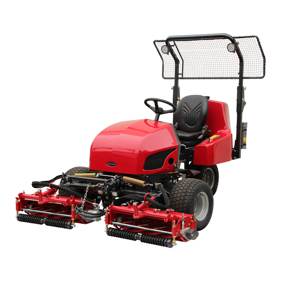
Baroness LM331 Owner's Operating Manual
3-unit surround & trim mower
Hide thumbs
Also See for LM331:
- Service manual (165 pages) ,
- Owner's operating manual (115 pages) ,
- Owner's operating manual (103 pages)

Related Manuals for Baroness LM331


Summary of Contents for Baroness LM331
- Page 1 3-Unit Surround & Trim Mower Owner's Operating Manual Serial No. LM331:10128- "Required reading" Read this manual before using the machine. Original Instructions Ver.1.5...
- Page 2 LM331 Regulations California Proposition 65 (For California, USA) WARNING: Operating, servicing and maintaining a passenger vehicle or off-road vehicle can expose you to chemicals including engine exhaust, carbon monoxide, phthalates, and lead, which are known to the State of California to cause cancer and birth defects or other reproductive harm.
- Page 3 LM331 Greeting Thank you for purchasing the Baroness product. This manual describes the proper handling, adjustment, and inspection of your product. We hope you will use the product safely, and take advantage of its best performance. For details on the handling, adjustment and inspection of the attachments, refer to the Owner's Operating Manual for the attachments.
- Page 4 The operator is responsible for operating the product properly and safely. Maintenance should only be performed by a certified specialist. If you have any questions concerning maintenance or genuine parts, please contact a Baroness dealer or Kyoeisha. When making inquiries about the product, please specify the product's model designation and serial number.
- Page 5 When replacing parts, be sure to use genuine Baroness parts or parts designated by Kyoeisha. Note that the Baroness product warranty may not apply to defects caused by the use of parts from other companies. Prior to use, carefully read the following manuals to thoroughly understand the contents for safe and correct operation.
- Page 6 LM331 Introduction...
-
Page 7: Table Of Contents
LM331 Contents Safety .............. Page 1-1 Safe Operating Practices .......Page 1-2 Disposal ............Page 2-1 Recycle and Waste Disposal ......Page 2-2 Product Overview .......... Page 3-1 Specifications ..........Page 3-2 Names of Each Section ......... Page 3-4 Regulation Decals ..........Page 3-4 Safety Signs and Instruction Signs .... - Page 8 LM331 Contents...
-
Page 9: Safety
LM331 Safety Safe Operating Practices ...... Page 1-2 Training ..........Page 1-2 Preparation ..........Page 1-2 Operation ..........Page 1-3 Maintenance and Storage ..... Page 1-4 Page 1-1... -
Page 10: Safe Operating Practices
LM331 Safety Failure to adequately follow these safety Never allow children or people unfamiliar precautions may cause an accident resulting in with these instructions to use or service the injury or death. machine. Local regulations may restrict the age of the... - Page 11 LM331 Safety Add fuel before starting the engine. Never Never operate across the face of the remove the cap of the fuel tank or add fuel slope, unless the machine is designed for while the engine is running or when the this purpose.
- Page 12 LM331 Safety Never operate while people, especially Maintenance and Storage children, or pets are nearby. Disengage drives on level ground, lower the Slow down and use caution when making attachments, set parking brake, stop engine turns and crossing roads and sidewalks.
- Page 13 LM331 Safety When checking the hydraulic circuit for pinhole leaks or oil leakage from nozzles, do not use your hands. Use items such as paper or corrugated cardboard to find leakage points. Be extremely careful with high-pressure oil as it may pierce your skin, resulting in an injury.
- Page 14 LM331 Safety Page 1-6 Safe Operating Practices...
-
Page 15: Disposal
LM331 Disposal Recycle and Waste Disposal ....Page 2-2 About Recycle ........Page 2-2 About Waste Disposal ......Page 2-2 Page 2-1... -
Page 16: Recycle And Waste Disposal
LM331 Disposal Recycle and Waste Disposal About Recycle Recycling battery etc. is recommended for environmental conservation and economical use of resources. It may be required by local laws. About Waste Disposal Make sure that waste generated when servicing or repairing the machine is disposed of in accordance with local regulations. -
Page 17: Product Overview
LM331 Product Overview Specifications ........Page 3-2 Specifications .........Page 3-2 Sound Pressure Level ......Page 3-3 Sound Power Level ....... Page 3-3 Vibration Level ........Page 3-3 Carbon Dioxide (CO2) Emissions Measurement .........Page 3-3 Names of Each Section ......Page 3-4 Regulation Decals ........Page 3-4... -
Page 18: Specifications
LM331 Product Overview Specifications Specifications Model LM331 Total length 100.00 in 254 cm Dimensions Total width 83.46 in 212 cm Total height ROPS 77.17 in 196 cm with groomer, CR brush, ROPS, light, LH unit 2006.17 lb 910 kg ball proof net without... -
Page 19: Sound Pressure Level
LM331 Product Overview Maximum inclination for operation 15 degrees Front wheel 20 x 12.00-10 4P Tire size Rear wheel 20 x 8.00-10 4P Front wheel 20.30 psi 140 kPa (1.4 kgf/cm Tire pneumatic pressure Rear wheel 20.30 psi 140 kPa (1.4 kgf/cm... -
Page 20: Names Of Each Section
LM331 Product Overview Names of Each Section Regulation Decals Positions of Regulation Decals G,H,I quwxcl-219 Names of Each Section_001 quwxcl-259 Hood Positions of Regulation Decals_001 Steering wheel Serial number plate Seat Specification decal Rear cover Noise emission decal Traveling pedal... -
Page 21: Regulation Decals
LM331 Product Overview Description of Regulation Decals Year of Manufacture Decal Serial Number Plate (For Europe) The year of manufacture decal indicates the The serial number plate indicates the model year when this machine was manufactured. and serial number of the machine. - Page 22 LM331 Product Overview Battery Capacity Decal Battery Danger Decal (For Europe) (For USA) The battery capacity decal indicates the Battery Danger Decal describes handling capacity by 20HR and CCA. precautions for battery. DANGER/POISON FLUSH EYES IMMEDIATELY WITH WATER SHIELD EYES...
- Page 23 LM331 Product Overview California Proposition 65 Decal (Riding Type) (For the State of California, USA) California Proposition 65 decal describes the warning messages as required by California Proposition 65. WARNING: Operating, servicing and maintaining a passenger vehicle or off-road vehicle can expose you to chemicals including...
-
Page 24: Safety Signs And Instruction Signs
6iul4h-151 Positions of Safety Decals and Instruction Decals_002 Part numbers for decals that need to be replaced are listed in the parts catalog. Order them from a Baroness dealer or Kyoeisha. Positions of Safety Decals and Instruction Decals 6iul4h-121... -
Page 25: Description Of Safety Decals And Instruction Decals
LM331 Product Overview Decal, left panel Caution Decal, diesel fuel filler Decal, hydraulic oil Rollover - Do not work on slopes of 15 Decal, keep away from fire degrees or more. Decal, caution for high temperatures When you descend a slope, drive at low speed with the mower units lowered. - Page 26 LM331 Product Overview Hydraulic Oil Icon Caution for High Temperatures Decal K4209000980 K4205001920 Hydraulic oil icon Decal, caution for high temperatures Read the Owner's Operating Manual. Caution High temperature - Do not touch. Otherwise, you will get burned. i77xz6-001 Hydraulic Oil Icon_001...
- Page 27 LM331 Product Overview Caution to Getting Entangled Decal Caution to Noise Decal K4205001910 K4205002090 Decal, caution to getting entangled Decal, caution to noise Warning Watch for rotating parts - Keep your hands away from the belts while the engine is running.
- Page 28 LM331 Product Overview Page 3-12 Safety Signs and Instruction Signs...
-
Page 29: Handling Instructions
LM331 Handling Instructions Inspections ..........Page 4-2 Light Switch ......... Page 4-24 Throttle Lever ........Page 4-24 Radiator ..........Page 4-2 Mower Unit Up/Down Lever ....Page 4-25 Coolant ..........Page 4-2 Reel Rotation Switch ......Page 4-25 Oil Cooler ..........Page 4-3 Reel Reverse Switch ......Page 4-26 Hydraulic Oil .......... -
Page 30: Inspections
LM331 Handling Instructions Carefully clean the front and back of the Inspections dust screen and radiator with water or compressed air. Inspect the machine according to the maintenance schedule so that you will be able to take advantage of its optimum performance for a long period of time. -
Page 31: Oil Cooler
LM331 Handling Instructions Coolant Supply Reserve tank Reserve tank cap Caution If no coolant is in the reserve tank, follow Do not touch the radiator or coolant during the steps below to fill the tank with clean engine operation or immediately after the water. -
Page 32: Hydraulic Oil
LM331 Handling Instructions Cleaning of Oil Cooler Important An unclean oil cooler may cause malfunction of the hydraulic system. Important Do not use solid objects, such as a spatula or screwdriver, or high-pressure water to clean olekci-005 the radiator or oil cooler. -
Page 33: Air Cleaner
LM331 Handling Instructions Start the engine, raise and lower the mower Cleaning of Air Cleaner units, and turn the steering wheel left and right. A contaminated air cleaner element may Move forward and reverse repeatedly cause malfunction of the engine. -
Page 34: Battery
LM331 Handling Instructions Battery Danger Danger When you supply battery fluid, wear protective Inspection of Battery garments and safety glasses, etc. Danger Danger If the battery fluid level is lower than Keep fire away while inspecting or charging halfway between the UPPER LEVEL the battery. -
Page 35: Brake
LM331 Handling Instructions Press the middle of the belt with your finger Brake to check the belt tension. Inspection of Brake Make sure that there are no cracks, damage or abnormal wear. While traveling, depress the brake pedal Wire firmly to make sure that the brake is applied effectively. -
Page 36: Fuel
LM331 Handling Instructions The appropriate oil level should be between Securely install the oil filler cap. the upper and lower limit lines on the gauge. gui678-019 Supply of Engine Oil_001 rnr453-004 Oil filler cap Inspection of Engine Oil_002 It will take a while for the supplied engine oil Oil level gauge to descend into the oil pan. -
Page 37: Water Separator
LM331 Handling Instructions Supply of Fuel Warning Do not supply fuel above F (FULL) level of the fuel gauge. If you supply too much fuel, it might overflow from the cap when you travel or work on a slope. v1spa6-007... - Page 38 LM331 Handling Instructions Remove the ring nut, and then remove the If the engine does not start within 15 cup. seconds after switching the ignition key to the "START" position, wait at least 30 seconds, and then repeat the same operation.
-
Page 39: Fuel Filter
LM331 Handling Instructions Remove the ring nut, and then remove the When the cup is filled with fuel, close the cup. air-bleed plug. If the engine does not start within 15 seconds after switching the ignition key to the "START" position, wait at least 30 seconds, and then repeat the same operation. -
Page 40: Tightening Torques
LM331 Handling Instructions Tightening Torques Important Refer to the Tightening Torque table. Note that the Baroness product warranty may not apply to defects caused by incorrect or overtorque tightening, etc. Standard Tightening Torques Bolts and Nuts Important A number of bolts are used in each part of this machine. - Page 41 LM331 Handling Instructions General bolt Strength classification 4.8 Nominal diameter tib3yb-001 kgf-cm lb-in 3 - 5 30.59 - 50.99 26.55 - 44.26 7 - 9 71.38 - 91.77 61.96 - 79.66 14 - 19 142.76 - 193.74 123.91 - 168.17 29 - 38 295.71 - 387.49...
-
Page 42: Principal Tightening Torques
LM331 Handling Instructions Principal Tightening Torques Tightening Torque by Model LM331 Tighten the following bolts and nuts at the torque specified in the table. For thread locking adhesive, apply a middle strength thread locker (ThreeBond 1322 or equivalent anaerobic sealant). -
Page 43: Adjustment Before Work
LM331 Handling Instructions Pull out the suspension adjustment handle Adjustment before Work and move it up or down to adjust the firmness of the seat suspension. Adjustment of Steering Wheel Observe the suspension adjustment scale while making adjustments. [50 - 160 kg Warning (110.2 - 352.7 lb)]... -
Page 44: Adjustment Of Mower Stopper Pin
LM331 Handling Instructions To release: Adjustment of Mower Stopper Pin Insert the cotter pin into the lower hole in the mower stopper pin. Note: Depending on the specifications, this function may not be available. The mower stopper pin can prevent or allow tilting of the mower units. -
Page 45: Procedure To Start/Stop Engine
LM331 Handling Instructions Adjustment of Mower Stabilizer (LH Unit) Procedure to Start/Stop Engine Note: Start/Stop of Engine Depending on the specifications, this function Procedure to Start Engine may not be available. Important Caution After adjusting the cutting height, adjust the Before starting the engine, make sure that mower stabilizer. - Page 46 LM331 Handling Instructions Shift the throttle lever from the "Low speed" Important position halfway to the "High speed" position. Quickly returning the ignition key from the "START" position to the "ON" position may Important result in damage to the device.
-
Page 47: Operation Method
LM331 Handling Instructions Safety Mechanisms Caution Never park the machine on a slope. This machine features a safety device for starting/stopping the engine. Positions of Operation Decals As for starting the engine, the safety device prevents the engine from starting unless it meets each of the following four conditions. -
Page 48: Positions Of Operation Decals
LM331 Handling Instructions Description of Operation Decals Key Switch Decal Key switch decal This indicates the key switch positions. STOP 6n6oux-198 Positions of Operation Decals_005 rcyo1p-002 Key Switch Decal_001 GLOW START 6n6oux-199 Engine Rotation Decal Positions of Operation Decals_006 Engine rotation decal This indicates high/low speed of the engine rotation. - Page 49 LM331 Handling Instructions Light Switch Decal Reel Rotation Mark Note: Reel rotation mark Depending on the specifications, this function It illustrates Rotation/Stop of the reel cutter may not be available. (cutting cylinder). LM331--1105Z0 Light switch decal This indicates the light switch positions.
- Page 50 LM331 Handling Instructions Tilt Steering Decal BRAKE Decal K4203001500 K4203001450 Tilt steering decal Decal, BRAKE This illustrates the tilt directions of the This indicates brake. steering wheel and the locked/free positions. BRAKE 7elqr2-001 hj3943-002 BRAKE Decal_001 Tilt Steering Decal_001 FORWARD Decal...
-
Page 51: Proximity Sensor
LM331 Handling Instructions Lapping switch decal Reel Stop Decal LM331--0556Z0 K4203001310 Lapping switch decal Decal, reel stop This indicates the ON/OFF positions for back This indicates stop of the reel cutter (cutting lapping. cylinder). v57o51-002 if834g-002 Lapping switch decal_001 Reel Stop Decal_001... -
Page 52: 2Wd/3Wd Selector Lever
LM331 Handling Instructions 2WD/3WD Selector Lever Caution Before switching between 2WD and 3WD operation, make sure that the machine is completely stopped. Caution Since traveling on steep downward slopes, bnec97-021 wet surfaces and wet grassy downward Light Switch_001 slopes in 3WD is dangerous, use 2WD. -
Page 53: Mower Unit Up/Down Lever
LM331 Handling Instructions Mower Unit Up/Down Lever Reel Rotation Switch Caution Caution Before raising or lowering the mower units, be Set the reel rotation switch to the "Rotation” sure to sit on the seat. position immediately before starting cutting work. At all other times, be sure to leave the reel rotation switch set to the "Stop"... -
Page 54: Reel Reverse Switch
LM331 Handling Instructions Reel Reverse Switch Reel Rotation/Stop Switching Lever Important Caution Do not switch the reel reverse switch to the Before operating the reel rotation/stop "ON" or "OFF" position while the reel cutter switching lever, be sure to set the reel rotation (cutting cylinder) is rotating. -
Page 55: Traveling Pedal
LM331 Handling Instructions Traveling Pedal Parking Brake Lever The traveling pedal is located in the right foot Caution area. When the forward end is depressed, the Never park the machine on a slope. machine travels forward. When the backward end is depressed, the machine travels Important backward. -
Page 56: Hood
LM331 Handling Instructions Lift up the hood. Hood Caution Do not open the hood in strong winds. Caution Be careful not to pinch your fingers when you open or close the hood. i5jb7e-023 Important Hood_003 Before opening the hood, be sure to lower the Hood mower units. -
Page 57: Center Cover
LM331 Handling Instructions Rear mounting bolts (two) Pull up the rear cover to remove it. uemj7o-008 uemj7o-011 Rear Cover_002 Rear Cover_005 Rear cover Rear cover Bolt Center Cover Bring the seat to the very front position. Bring the seat to the backmost position. -
Page 58: Instruments
LM331 Handling Instructions Battery Cutoff Switch Water temperature gauge Fuel gauge Important Pilot lamps (charge lamp, thermo-start lamp, and After disconnecting, switch the ignition key to oil pressure lamp) the "ON" position and check that the charge lamp and oil pressure lamp do not turn on. -
Page 59: Fuel Gauge
LM331 Handling Instructions Fuel Gauge Thermo-start Lamp The fuel gauge is located in the meter panel. The thermo-start lamp is the middle pilot This instrument indicates the quantity of fuel lamp, located in the meter panel. inside the fuel tank. -
Page 60: Travel Of Machine
LM331 Handling Instructions Travel of Machine Overheat Warning Buzzer If the water temperature inside the engine Traveling Procedure exceeds 105 degrees Celsius, a buzzer will sound. (intermittent tone) Caution Remove the load from the engine, idle the Under any circumstances drive the machine at... -
Page 61: Towing The Machine
LM331 Handling Instructions Secure the machine with ropes. Towing The Machine Front side If the machine does not travel due to engine trouble, etc., you can move it in the following ways: Pushing by hand ・ ・ Towing (See the following procedure.) -
Page 62: Cutting Work
LM331 Handling Instructions Shift the reel rotation/stop switching levers of Piston pump all mower units to the "Rotation" position. Unload valve Start the engine. Bolt "Procedure to Start Engine" (Page 4-17) Lock nut Raise all mower units. Remove the wheel stoppers. -
Page 63: Transporting
LM331 Handling Instructions Removal/Installation of Grass Catcher Grass catcher Grass catcher mounting bracket Caution Mounting pin Stop the engine before removing or installing Mower unit #3 the grass catcher. Set the reel rotation switch to the "Stop" position. Lower the mower units. - Page 64 LM331 Handling Instructions Page 4-36 Storage...
-
Page 65: Maintenance
LM331 Maintenance Maintenance Precautions ..... Page 5-2 Maintenance Schedule ......Page 5-3 Adjusted Value ........Page 5-6 Jacking Up The Machine .......Page 5-7 About Jacking Up The Machine .....Page 5-7 Jack-up Points ........Page 5-7 Lifting Points .......... Page 5-8 Greasing .......... -
Page 66: Maintenance Precautions
Use tools appropriate for each maintenance operation. Important For the safe and best performance of your machine, use Baroness genuine parts for replacement and accessories. Please note that our product warranty may be void if you use non-genuine parts for replacement or accessories. -
Page 67: Maintenance Schedule
LM331 Maintenance Maintenance Schedule LM331 Follow the maintenance schedule below. ○・・・Inspect, adjust, supply, clean ●・・・Replace (first time) △・・・Replace Maintenance Item Remarks Check engine oil level ○ ... - Page 68 LM331 Maintenance Maintenance Item Remarks Clean radiator core ○ Clean oil cooler core ○ ...
- Page 69 LM331 Maintenance Maintenance Item Remarks Check every 100 hours or Check exterior of battery ○ ○ every month whichever comes earlier Check every 100 hours or Clean exterior of battery ...
-
Page 70: Adjusted Value
△ ・ *1: Consult your local Baroness Dealer or local KUBOTA Dealer for this service. The items above (*2 marked) are registered as emission related critical parts by KUBOTA in the ・... -
Page 71: Jacking Up The Machine
LM331 Maintenance Jacking Up The Machine Jack-up Points Front right frame About Jacking Up The Machine Front left frame Rear right frame Warning Rear left frame When replacing a tire or beginning any other Front right frame maintenance or repairs, be sure to chock the wheels to prevent the machine from moving. -
Page 72: Lifting Points
LM331 Maintenance Rear left frame Front left frame rwyt62-096 b5geiy-006 Jack-up Points_005 Lifting Points_003 Lifting Points Important Be sure to use adequately strong cables. b5geiy-004 Lifting Points_001 Lifting points Front right frame Front left frame Front right frame b5geiy-005... -
Page 73: Greasing
LM331 Maintenance Greasing No. of Location greasing About Greasing points Lift arm fulcrum Since there may be adhesion or damage due Mower arm fulcrum to lack of grease on moving parts, they must be greased. Brake pedal shaft fulcrum Add urea-based No. - Page 74 LM331 Maintenance Mower arm fulcrum Brake lever shaft Add grease every 100 hours of operation or Mower unit #1 every year, whichever comes earlier. There is one greasing point on the mower #10001-10027 arm fulcrum. 8bq62b-273 8bq62b-271 Greasing Points_007 Greasing Points_004...
- Page 75 LM331 Maintenance Tension lever Front wheel brake lever There is one greasing point each on the left and right sides. Left side 8bq62b-275 Greasing Points_010 Neutral cam lever 8bq62b-330 Greasing Points_014 Right side 8bq62b-276 Greasing Points_011 Traveling pedal shaft fulcrum...
-
Page 76: Lubrication
LM331 Maintenance Mower coupling Steering cylinder spherical bearing Mower unit #2 and #3 There are two locations. There is one greasing point each on the couplings connecting the mower units. 8bq62b-487 Lubricating Points_002 8bq62b-347 Front mower cylinder spherical bearing There are two locations. -
Page 77: Maintenance Work
LM331 Maintenance Rear mower cylinder spherical bearing Rear Tires There is one location. Follow the steps below to remove the rear tires Loosen the bolts. 8bq62b-490 Lubricating Points_005 Maintenance Work upekw4-002 Removing/Installing Tires Rear Tires_001 Heat-treated bolt Front Tires Securely place the jack beneath the jack-up... -
Page 78: Adjustment Of Belt Tension
LM331 Maintenance Adjustment of Belt Tension Hydraulic Pump Drive Belt Open the hood. Warning Be sure to stop the engine before adjusting the belts. Important Before making sure of belt tension, rotate the belt several times. If the belt becomes slack due to frequent use, it may jump or slip. -
Page 79: Adjustment Of Parking Brake
LM331 Maintenance Make adjustment with the adjustment bolt Adjustment of Parking Brake so as to locate position of the latch at 3 to 4 notches from the bottom. Caution Make sure that the brake wire is not cracked or damaged. -
Page 80: Adjustment Of Brake
LM331 Maintenance If the left and right brakes are not equally Adjustment of Brake effective, make fine adjustments with the adjustment bolt on the brake wire. Caution Break-In of Brakes If the brake wire becomes broken, the If the brake shoes or brake pads are worn, machine will be unable to stop. - Page 81 LM331 Maintenance Make sure that the length of the spring of the Cam lever lever adjuster is 53.0 mm (2.09 in). Cam lever shaft bolt Loosen the lock nut as necessary to make Lever adjustment bracket adjustment. Start the engine, and rev it up to the maximum rpm.
-
Page 82: Change Of Coolant
LM331 Maintenance Relationship between concentration of long-life Change of Coolant coolant (LLC) and freezing temperature LLC concentration Caution Freezing temperature (volume %) Do not touch the radiator or coolant during Down to -10 °C (14 °F) 20 % engine operation or immediately after the Down to -15 °C (5 °F) -
Page 83: Change Of Hydraulic Oil
LM331 Maintenance Remove the reserve tank. Change of Hydraulic Oil Caution Be careful with hot oil, which could cause burns if it contacts your skin. Important When you change the hydraulic oil, be sure to drain it into a bowl and discard it in ouuoov-023 accordance with local laws and regulations. -
Page 84: Change Of Hydraulic Oil Filter
LM331 Maintenance Follow the steps below to supply new Important hydraulic oil. The hydraulic tank capacity is approximately If the hydraulic oil emulsifies or if it becomes 26.0 dm (26.0 L). even slightly less transparent, change the oil immediately. Open the tank cap, and then supply... -
Page 85: Change Of Air Cleaner
LM331 Maintenance Lightly coat the O-ring of the new filter Filter cartridge cartridge with hydraulic oil, and then install Filter case the cartridge. Body Supply hydraulic oil until it reaches the specified level. "Hydraulic Oil Supply" (Page 4-4) Change of Air Cleaner A contaminated air cleaner element may cause malfunction of the engine. -
Page 86: Change Of Engine Oil
LM331 Maintenance Remove the oil filler cap, and then supply Change of Engine Oil new engine oil until the oil reaches a level in between the upper and lower limit lines on Caution the oil level gauge. Engine oil quantity is approximately 3.7 dm Be careful with hot oil, which could cause (3.7 L). -
Page 87: Change Of Engine Oil Filter
LM331 Maintenance Make sure that there is no oil leakage at the Change of Engine Oil Filter sealing surface of the filter cartridge. Check the engine oil level. Caution If it is low, supply engine oil until it reaches Be careful with hot oil, which could cause the specified level. -
Page 88: Change Of Fuse
LM331 Maintenance Change of Fuse O-ring Element Fuse Box Ring nut Important Clean the inside of the filter cup with diesel Before performing maintenance on the fuel. electrical system, be sure to disconnect the negative terminal of the battery. Important... - Page 89 LM331 Maintenance Fusible Link Fuse capacities of the fusible links are 30 A and 50 A. A B C D E Engine stop solenoid: 30 A H I J pkm25s-003 Fuse Box_002 Glow lamp timer Glow lamp Charge lamp, oil pressure lamp (engine oil...
- Page 90 LM331 Maintenance Page 5-26 Maintenance Work...
- Page 94 1-26, Miyuki-cho, Toyokawa-city, Tel : +81 - 533 - 84 - 1390 Head Office Fax : +81 - 533 - 84 - 1220 Aichi-pref, 442-8530 JAPAN LM331---UM--GBZ/20M-00-S.K E01[LM331_EU01]...
Need help?
Do you have a question about the LM331 and is the answer not in the manual?
Questions and answers