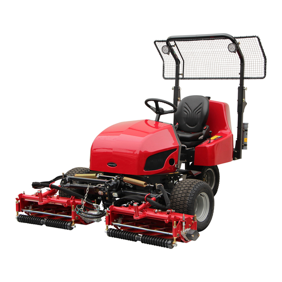
Baroness LM331 Owner's Operating Manual
3-unit surround & trim mower
Hide thumbs
Also See for LM331:
- Service manual (165 pages) ,
- Owner's operating manual (115 pages) ,
- Owner's operating manual (103 pages)
Table of Contents
Advertisement
Quick Links
Download this manual
See also:
Service Manual
Advertisement
Chapters
Table of Contents

Related Manuals for Baroness LM331


Summary of Contents for Baroness LM331
- Page 1 3-Unit Surround & Trim Mower Owner's Operating Manual Serial No. LM331:10001- "Required reading" Read this manual and the Owner's Manual for the engine before using the machine. Original Instructions Ver.1.0...
- Page 2 LM331 Regulations California Proposition65 (For California, USA) WARNING: Operating, servicing and maintaining a passenger vehicle or off-road vehicle can expose you to chemicals including engine exhaust, carbon monoxide, phthalates, and lead, which are known to the State of California to cause cancer and birth defects or other reproductive harm.
- Page 3 LM331 Greeting Thank you for purchasing the Baroness machine. This manual explains proper handling, adjustment, and inspection of your machine. Prior to use, carefully read this manual to thoroughly understand the contents for safe and correct operation. We hope you will use the machine safely, and take advantage of its best performance.
- Page 4 The information described in this manual is subject to change for improvement without prior notice. When replacing parts, be sure to use genuine Baroness parts or parts designated by Kyoeisha. Note that the Baroness product warranty may not apply to defects caused by the use of parts from other companies.
- Page 5 LM331 Introduction Purpose This machine is intended for cutting turf grass at golf courses. Do not use this machine in any way other than its intended purpose, and do not modify the machine. Operating this machine for other purposes and modifying it may be very dangerous and may cause damage to the machine.
- Page 6 LM331 Introduction...
-
Page 7: Table Of Contents
LM331 Contents Safety .............. Page 1-1 Safe Operating Practices .......Page 1-2 Disposal ............Page 2-1 Recycle and Waste Disposal ......Page 2-2 Product Overview .......... Page 3-1 Specifications ..........Page 3-2 Names of Each Section ......... Page 3-4 Safety Signs and Instruction Signs ....Page 3-6 Handling Instructions ........ - Page 8 LM331 Contents...
-
Page 9: Safety
LM331 Safety Safe Operating Practices ...... Page 1-2 Training ..........Page 1-2 Preparation ..........Page 1-2 Operation ..........Page 1-3 Maintenance and storage ...... Page 1-4 Page 1-1... -
Page 10: Safe Operating Practices
LM331 Safety Failure to adequately follow these safety Incorrect hitching and load distribution precautions may cause an accident resulting in Never allow children or people unfamiliar injury or death. with these instructions to use or service the machine. Danger Danger... - Page 11 LM331 Safety Check that operator's presence controls, Do not change the engine governor settings safety switches and shields are attached and or overspeed the engine. Operating the functioning properly. Do not operate unless engine at excessive speed may increase the they are functioning properly.
- Page 12 LM331 Safety Take care when loading or unloading the Never allow untrained personnel to service machine into a trailer or a truck. Load or machine. unload the machine in a flat and safe place. Allow the engine/muffler to cool before Before loading or unloading, set the parking checking/maintenance.
- Page 13 LM331 Safety Charge batteries in an open well ventilated area, away from spark and flames. Unplug charger before connecting or disconnecting from battery. Wear protective clothing and use insulated tools. Keep all parts in good working condition and all hardware tightened. Replace all worn or damaged decals.
- Page 14 LM331 Safety Page 1-6 Safe Operating Practices...
-
Page 15: Disposal
LM331 Disposal Recycle and Waste Disposal ....Page 2-2 About Recycle ........Page 2-2 About the Waste disposal ...... Page 2-2 Page 2-1... -
Page 16: Recycle And Waste Disposal
LM331 Disposal Recycle and Waste Disposal About Recycle Recycling battery etc. is recommended for environmental conservation and economical use of resources. It may be required by local laws. About the Waste disposal Make sure that waste generated when servicing or repairing the machine is disposed of in accordance with local regulations. -
Page 17: Product Overview
LM331 Product Overview Specifications ........Page 3-2 Specifications .........Page 3-2 Sound pressure level ......Page 3-3 Sound power level ......... Page 3-3 Vibration level ........Page 3-3 Names of Each Section ......Page 3-4 Serial Number Plate .......Page 3-4 Specification Decal ........ Page 3-5 Noise Emission Decal ......Page 3-5... -
Page 18: Specifications
LM331 Product Overview Specifications Specifications Model LM331 Total length 100.00 in 254 cm Dimensions Total width 83.46 in 212 cm Total height ROPS 77.17 in 196 cm with groomer, CR brush, ROPS, Light, LH unit 2006.17 lb 910 kg Ball proof net without... -
Page 19: Sound Pressure Level
LM331 Product Overview Tire size Rear wheel 20 x 8.00-10 4P Front wheel 20.30 psi 140 kPa (1.4 kgf/cm Tire pneumatic pressure Rear wheel 20.30 psi 140 kPa (1.4 kgf/cm Battery 75D23L The factory default maximum engine rpm is 2,800 rpm. -
Page 20: Names Of Each Section
LM331 Product Overview Names of Each Section F,G,H quwxcl-075 Names of Each Section_002 quwxcl-074 Serial number plate Names of Each Section_001 Specification decal Hood Noise emission decal Steering wheel Year of manufacture decal Seat ROPS compliance decal Rear cover Battery capacity decal... -
Page 21: Specification Decal
LM331 Product Overview Specification Decal ROPS Authentication Decal (For Europe) The ROPS authentication decal indicates the The Specification decal indicates the CE manufacturer, model, etc., in accordance with marking, model , and weight, etc. International Standard ISO 21299:2009. kj8jic-001 c3td3e-003... -
Page 22: Safety Signs And Instruction Signs
Positions of Safety Decals and Instruction Decals_002 peel off, replace them with new ones. Part numbers for decals that need to be replaced are listed in the parts catalog. Order them from a Baroness dealer or Kyoeisha. 6iul4h-103 Positions of Safety Decals and Instruction Decals_003... - Page 23 LM331 Product Overview 6iul4h-104 Positions of Safety Decals and Instruction Decals_004 6iul4h-105 Positions of Safety Decals and Instruction Decals_005 Safety Signs and Instruction Signs Page 3-7...
-
Page 24: Description Of Safety Decals And Instruction Decals
LM331 Product Overview Description of Safety Decals and Instruction Decals LM3800-0928Z0 Left panel decal Warning Read the Owner's Operating Manual. Warning Apply the parking brake, stop the engine, and then remove the ignition key before leaving the machine. - Page 25 LM331 Product Overview K4209001000 Decal, diesel fuel filler Use diesel fuel. K 4 2 0 9 0 0 1 0 0 0 qigqnx-021 K4209001330 LOW SULFUR OR Decal, diesel instructions ULTRA LOW SULFUR (For USA) DI ESEL FUEL ONLY Use low sulfur or ultra-low sulfur diesel fuel (sulfur-free K4209001330 diesel fuel).
- Page 26 LM331 Product Overview K4205001970 Decal, caution for spouting coolant Caution Caution for spouting coolant - Do not open while hot. qigqnx-045 K4205001710 Decal, ROPS caution Replace damaged ROPS. Do not repair or modify. (Only if equipped with ROPS) qigqnx-072 K4205001560...
-
Page 27: Handling Instructions
LM331 Handling Instructions Inspection Before Use ......Page 4-2 Light Switch ......... Page 4-25 Throttle Lever ........Page 4-26 Radiator ..........Page 4-2 Mower Unit Up/Down Lever ....Page 4-26 Coolant ..........Page 4-3 Stop Valve ........... Page 4-27 Oil cooler ..........Page 4-4 Reel Rotation Switch ...... -
Page 28: Inspection Before Use
LM331 Handling Instructions Inspection Before Use Hood Dust screen Be sure to perform an inspection before you Carefully clean the front and back of the start using the machine so that you will be able dust screen and radiator with water or to take advantage of its optimum performance compressed air. -
Page 29: Coolant
LM331 Handling Instructions Coolant Caution The radiator cap is pressurized. Inspection of Coolant If you remove the radiator cap while the For details on handling the engine, please engine is overheated, hot steam will burst out, refer to the Owner's Manual for the engine. -
Page 30: Oil Cooler
LM331 Handling Instructions If no coolant is in the reserve tank, follow If the oil cooler has been contaminated with the steps below to fill the tank with clean dust, be sure to clean it. water. Especially after operating the machine in a... -
Page 31: Air Cleaner
LM331 Handling Instructions Air Cleaner Hydraulic Oil Supply Inspection of Air Cleaner Important For details on handling the engine, please Do not mix different types of oil. refer to the Owner's Manual for the engine. The air cleaner is a component that removes... -
Page 32: Battery
LM331 Handling Instructions Battery Cleaning of Air Cleaner For details on handling the engine, please Inspection of Battery refer to the Owner's Manual for the engine. For details on handling the battery, please A contaminated air cleaner element may refer to the separate Battery Instruction cause malfunction of the engine. -
Page 33: Tire
LM331 Handling Instructions Supply of Battery Fluid Tire size Pneumatic pressure Front 140 kPa For details on handling the battery, please whee 20 x 10.00 - 10 refer to the Battery's Owner's Manual. (1.4 kgf/cm Danger Danger Rear 140 kPa whee 20 x 8.00 - 10... -
Page 34: Belt
LM331 Handling Instructions Belt Engine Oil Inspection of Belt Inspection of Engine Oil For details on handling the engine, please Caution refer to the Owner's Manual for the engine. The engine must be stopped when the belt is Important inspected. -
Page 35: Fuel
LM331 Handling Instructions Fuel Supply of Engine Oil For details on handling the engine, please Inspection of Fuel Quantity refer to the Owner's Manual for the engine. With the machine on a level surface, observe Important the fuel gauge in the meter panel to check the fuel level. -
Page 36: Water Separator
LM331 Handling Instructions Close the fuel cock of the water separator. Tank cap Water Separator Inspection of Water Separator Important Water-contaminated fuel may impair engine startability, decrease output or damage engine parts. v1spa6-005 The water separator removes water from the Draining of Water Separator_001 fuel. - Page 37 LM331 Handling Instructions Open the fuel cock of the water separator. Close the fuel cock of the water separator. v1spa6-005 v1spa6-005 Draining of Water Separator_003 Cleaning of Water Separator_001 Fuel cock Fuel cock Air-bleeding plug Air-bleeding plug ON (open) ON (open)
-
Page 38: Fuel Filter
LM331 Handling Instructions Open the fuel cock of the water separator. Be sure to retighten the parts. Check the bottom of the machine for oil and grease leakage. Grass Catcher Inspection of Grass Catcher The grass catcher may no longer correctly collect grass clippings due to its wear, damage, deformation, etc., caused by... -
Page 39: Tightening Torques
LM331 Handling Instructions Tightening torques Standard tightening torques Bolts and Nuts Important A number of bolts are used in each part of this machine. Be sure to re-tighten the bolts and nuts, because they may be loosened at the earlier stage of the use. - Page 40 LM331 Handling Instructions Heat-treated bolt Strength classification 8.8 Strength classification 10.9 Nominal diameter 10.9 tib3yb-002 tib3yb-003 kgf-cm lb-in kgf-cm lb-in 5 - 7 50.99 - 71.38 44.26 - 61.96 7 - 10 71.38 - 101.97 61.96 - 88.51 8 - 11 81.58 - 112.17...
-
Page 41: Principal Tightening Torques
23 - 38 387.49 336.34 683.20 - 593.02 - Hydraulic pump K0010120502 BOLT, HT M12-50 67 - 134 1366.40 1186.03 LM331--0722Z2 BOLT, STEPPED M12 ○ Steering cylinder K0000080202 BOLT, M8-20 ○ 683.20 - 593.02 - ROPS K0010120402 BOLT, HT M12-40 67 - 134 1366.40... -
Page 42: Adjustment Before Operating
LM331 Handling Instructions Pull out the suspension adjustment handle Adjustment Before Operating and move it up or down to adjust the firmness of the seat suspension. Adjustment of Steering Wheel Observe the suspension adjustment scale while making adjustments. (50 - 160 kg) -
Page 43: Adjustment Of Mower Stabilizer
LM331 Handling Instructions To fix: When mowing on a markedly uneven surface, Insert the cotter pin into the upper hole in the shorten (compress) the spring. mower stopper pin. Lower all mower units on a level place. Apply the parking brake, and then stop the engine. -
Page 44: Procedure To Start / Stop Engine
LM331 Handling Instructions Shift the throttle lever from the turtle icon Procedure to Start / Stop Engine (low speed) halfway to the rabbit icon (high speed). Start / Stop of Engine Important Procedure to Start Engine The thermo-start lamp turns off at the Warning specified time. -
Page 45: Safety Mechanisms
LM331 Handling Instructions After the thermo-start lamp turns off, Close the fuel cock of the fuel filter. immediately set the ignition key to the Close the fuel cock of the water separator. "START" position. Safety Mechanisms Caution This machine features a safety device for Quickly returning the ignition key from the starting/stopping the engine. -
Page 46: Operation Of Each Section
LM331 Handling Instructions Operation of Each Section Precautions for Operating the Machine Caution Under any circumstances drive the machine at such a speed that you can stop it immediately for emergencies. Cautions for when You Leave the Machine 6n6oux-139 Operation Decals_003... - Page 47 LM331 Handling Instructions 6n6oux-142 Operation Decals_006 Decal, lapping switch 6n6oux-143 Operation Decals_007 Decal, reel rotation Decal, reel stop Operation of Each Section Page 4-21...
- Page 48 LM331 Handling Instructions STOP Decal, key switch This indicates the key switch positions. 1. OFF 2. ON 3. GLOW 4. START 6n6oux-021 Decal, engine rotation This indicates the low/high speed of engine rotation. 1. High speed 2. Low speed 6n6oux-144...
- Page 49 LM331 Handling Instructions Decal, stop valve operation It illustrates Stop/Open of the stop valve. 1. Stop 2. Open 6n6oux-145 Decal, 2WD/3WD selector lever This indicates the 2WD/3WD positions. 1. 3WD 2. 2WD 6n6oux-148 K4203001500 Decal, tilt steering This illustrates the tilt directions of the steering wheel and the locked/free positions.
- Page 50 LM331 Handling Instructions K4203001430 Decal, FORWARD This indicates forward travel. 6n6oux-128 K4203001440 Decal, BACKWARD This indicates backward travel. 6n6oux-129 LM3800-0556Z0 Decal, lapping switch This indicates the ON/OFF positions for back lapping. 1. ON (back lapping rotation) 2. OFF (mowing rotation)
-
Page 51: Proximity Sensor
LM331 Handling Instructions Proximity Sensor There is a proximity sensor on #2 mower arm fulcrum. This sensor detects the raised or lowered positions of mower unit #2. The information is related to controlling rotation and stop of the reel cutter (cutting cylinder). -
Page 52: Throttle Lever
LM331 Handling Instructions The mower unit up/down lever is located in the Throttle Lever operation panel (to the right of the driver's seat) and raises or lowers the mower units. The throttle lever is located in the meter panel Shift the lever to the "DOWN" position to lower and enables you to adjust the engine rpm. -
Page 53: Stop Valve
LM331 Handling Instructions Stop Valve Caution When you move the machine, or if you stop the engine with the mower units raised, be sure to set the stop valve to the "Stop" position. The stop valve is located in the operation panel (to the right of the driver's seat). -
Page 54: Reel Rotation/Stop Switching Lever
LM331 Handling Instructions Reel reverse switch ON (reverse rotation) OFF (normal rotation) Reel rotation/stop switching lever Caution Before operating the reel rotation/stop switching lever, be sure to set the reel rotation switch to the "Stop" position. yo3h9x-010 Traveling Pedal_001 The reel rotation/stop switching lever is located Traveling pedal on the reel motor attached to each mower unit. -
Page 55: Parking Brake Lever
LM331 Handling Instructions Loosen the lock bolt for the hood. Parking Brake Lever Caution Be sure to release the parking brake before driving. Otherwise, the brakes or hydraulic system may malfunction. Caution Never park the machine on a slope. i5jb7e-021... -
Page 56: Rear Cover
LM331 Handling Instructions If the ball proof net is installed, follow the Rear Cover steps below to fold back the ROPS. Remove the clip pins on the left and right Caution sides of the ROPS, and then remove the Do not open the rear cover in strong winds. -
Page 57: Instruments
LM331 Handling Instructions Center Cover Caution Be careful not to pinch your fingers when you open or close the cover. Bring the seat to the backmost position. Completely raise the steering wheel. Remove the bolt on each side of the center 16lvzs-001 cover. -
Page 58: Water Temperature Gauge
LM331 Handling Instructions Water Temperature Gauge Pilot Lamps The water temperature gauge is located in the Charge Lamp meter panel. The charge lamp is the left pilot lamp, located This instrument indicates the water in the meter panel. temperature inside the engine. -
Page 59: Travel Of Machine
LM331 Handling Instructions Thermo-start lamp Oil pressure lamp The oil pressure lamp is the right pilot lamp, located in the meter panel. This lamp turns on when the ignition key is set to the "ON" position before the engine starts. -
Page 60: Towing The Machine
LM331 Handling Instructions Loosen the lock nut on each of the two Towing the Machine unload valves. If the machine does not travel due to engine Tighten the two bolts to compress the unload trouble, etc., you can move it in the following... -
Page 61: Cutting Work
LM331 Handling Instructions Set the reel rotation switch to the "Rotation" Cutting Work position to rotate the reel cutters (cutting cylinders) of all mower units. Cutting Work Depress the traveling pedal to start cutting work. Warning Removal/Installation of Grass Catcher Do NOT start to move or stop the machine abruptly. -
Page 62: Transporting
LM331 Handling Instructions Mower unit #2 bos35l-003 Removal/Installation of Grass Catcher_002 Grass catcher Grass catcher mounting bracket Mounting pin Mower unit #3 bos35l-004 Removal/Installation of Grass Catcher_003 Grass catcher Grass catcher mounting bracket Mounting pin Transporting Transporting Procedure When loading the machine into a trailer or a truck to transport it, drive the machine forward. -
Page 63: Maintenance
LM331 Maintenance Maintenance Precautions ..... Page 5-2 Maintenance Schedule ......Page 5-2 Specified Values ........Page 5-6 Jacking up the machine ......Page 5-6 About the Jacking up the machine ..Page 5-6 Jack-up Points ........Page 5-6 Lifting Points .......... Page 5-7 Greasing .......... -
Page 64: Maintenance Precautions
Use tools appropriate for each maintenance operation. Caution For the safe and best performance of your machine, use Baroness genuine parts for replacement and accessories. Please note that our product warranty may be void if you use non-genuine parts for replacement or accessories. - Page 65 LM331 Maintenance Maintenance Item Remarks Check traveling pedal ○ motion Refer to Check brake function "Inspection of ○ ...
- Page 66 LM331 Maintenance Maintenance Item Remarks 100 hours Change engine oil ● △ thereafter 50 hours first change, every Replace oil filter cartridge ● △ ...
- Page 67 Replace battery △ *1: Consult your local Baroness Dealer or local KUBOTA Dealer for this service. ・ ・ The items above (*2 marked) are registered as emission related critical parts by KUBOTA in the U.S.
-
Page 68: Jacking Up The Machine
LM331 Maintenance Specified Values Fuel tank capacity Diesel fuel 25.0 dm (25.0 L) Hydraulic tank capacity Shell Tellus S2M46 or equivalent 26.0 dm (26.0 L) Quantity of engine oil API Service grade class CF or higher 3.7 dm (3.7 L) -
Page 69: Lifting Points
LM331 Maintenance Front right frame Lifting Points Important Be sure to use adequately strong cables. rwyt62-093 Jack-up Points_002 Front left frame b5geiy-004 Lifting Points_001 Lifting points Front right frame Front left frame Front right frame rwyt62-094 Jack-up Points_003 Rear right frame... -
Page 70: Greasing
LM331 Maintenance Greasing No. of Location greasing About Greasing points Lift arm fulcrum Since there may be adhesion or damage due Mower arm fulcrum to lack of grease on moving parts, they must be greased. Brake pedal shaft fulcrum Add urea-based No. - Page 71 LM331 Maintenance Mower arm fulcrum Rear wheel housing Mower unit #1 There is one greasing point on the mower arm fulcrum. 8bq62b-274 Greasing Points_007 Tension lever 8bq62b-271 Greasing Points_004 Brake pedal shaft fulcrum 8bq62b-275 Greasing Points_008 Neutral cam lever 8bq62b-272...
-
Page 72: Maintenance (Main Body)
Heat-treated bolt Refer to the Tightening Torque Table. Securely place the jack beneath the jack-up Note that the Baroness product warranty may point of the front left/right frame area, and not apply to defects caused by incorrect or then raise it until the tire lifts off the ground. -
Page 73: Adjustment Of Belt Tension
LM331 Maintenance Adjustment of Belt Tension Hydraulic Pump Drive Belt Caution Caution Be sure to stop the engine before adjusting Be sure to stop the engine before adjusting the belts. the belts. Open the hood. Important With your finger, lightly press the middle of Make sure that the belt has the specified the belt with a force of 25 to 35 N (2.5 to 3.5... -
Page 74: Adjustment Of Parking Brake
LM331 Maintenance Adjustment of Parking Brake Danger Danger Make sure that the brake wire is not cracked or damaged. Danger Danger Make sure that the brake is effective on slopes and that it is not applied any longer ulabms-007 when you release it. -
Page 75: Adjustment Of Brake
LM331 Maintenance Adjustment of Brake Danger Danger It would be extremely dangerous and may Danger Danger result in an unexpected accident if the left and right brakes are not equally effective. If the brake wire is cut, the machine will be unable to stop. - Page 76 LM331 Maintenance Place the jacks beneath the jack-up points, Slide the cam lever and tighten the cam and then lift the machine off the ground. lever shaft bolt. Use stable jack stands, and raise the machine until the tires lift off the ground.
-
Page 77: Change Of Coolant
LM331 Maintenance Change of Coolant Caution Be careful with hot oil, which could cause For details on handling the engine, please refer burns if it contacts your skin. to the Owner's Manual for the engine. Warning Important When changing the coolant, be sure to drain it... -
Page 78: Replacement Of Hydraulic Oil Filter
LM331 Maintenance Follow the steps below to supply new Caution hydraulic oil. The hydraulic tank capacity is approximately Be careful with hot oil, which could cause burns if it contacts your skin. 26.0 dm (26.0 L). Open the tank cap, and then supply... -
Page 79: Change Of Air Cleaner
LM331 Maintenance Lightly coat the O-ring of the new filter Filter cartridge cartridge with hydraulic oil, and then install Filter case the cartridge. Body Supply hydraulic oil until it reaches the specified level. "Hydraulic Oil Supply" (Page 4-5) Change of Air Cleaner For details on handling the engine, please refer to the Engine's Owner's Manual. -
Page 80: Replacement Of Engine Oil
LM331 Maintenance Re-place the drain plug. Replacement of Engine Oil Remove the oil filler cap, and then supply For details on handling the engine, please refer new engine oil until the oil reaches a level in to the Owner's Manual for the engine. -
Page 81: Replacement Of Engine Oil Filter
LM331 Maintenance Start the engine, and then stop it after 10 to Replacement of Engine Oil Filter 20 minutes. For details on handling the engine, please refer Make sure that there is no oil leakage at the to the Owner's Manual for the engine. -
Page 82: Change Of Fuse
LM331 Maintenance O-ring Caution Element If a fuse blows, a short may have occurred within the electrical circuit. Ring nut Check for the cause, such as faulty terminal connections, damaged wiring or terminals, or Clean the inside of the filter cup with diesel incorrect wiring. -
Page 83: Long-Term Storage
LM331 Maintenance Battery: 50 A Glow lamp timer Glow lamp Charge lamp, oil pressure lamp (engine oil pressure lamp), water temperature gauge, buzzer, solenoid timer, hour meter, fuel gauge Reel normal rotation solenoid, reel reverse 15 A rotation solenoid 15 A (Unused) - Page 84 LM331 Maintenance Page 5-22 Long-Term Storage...
- Page 88 Head Office 1-26, Miyuki-cho, Toyokawa, Tel : (0533) 84 - 1390 Fax : (0533) 89 - 3623 Aichi-Pref. 442-8530 Japan. LM331---UM--GBZ/18B-00-S.K E00[LM331_EU00]...
Need help?
Do you have a question about the LM331 and is the answer not in the manual?
Questions and answers