
Related Manuals for Baroness LM311


Summary of Contents for Baroness LM311
- Page 1 Riding Greens Mower Owner's Operating Manual Serial No. LM311:10001- "Required reading" Read this manual before using the machine. Original Instructions Ver.1.0...
- Page 2 LM311 Regulations California Proposition 65 California Spark Arrester (For California, USA) (For California, USA) Warning WARNING: Operation of this equipment may create Operating, servicing and maintaining sparks that can start fires around dry a passenger vehicle or off-road vegetation. vehicle can expose you to chemicals A spark arrester may be required.
- Page 3 LM311 Greeting Thank you for purchasing the Baroness product. QR Code This manual describes the proper handling, adjustment, and inspection of your product. A QR code label is affixed on the machine. We hope you will use the product safely, and take advantage of its best performance.
- Page 4 The operator is responsible for operating the product properly and safely. Maintenance service for this machine should be performed by a mechanic with expertise. If you have any questions concerning maintenance or genuine parts, please contact a Baroness dealer or Kyoeisha.
- Page 5 When replacing parts, be sure to use genuine Baroness parts or parts designated by Kyoeisha. Note that the Baroness product warranty may not apply to defects caused by the use of parts from other companies. Prior to use, carefully read the following manuals to thoroughly understand the contents for safe and correct operation.
- Page 6 LM311 Introduction...
-
Page 7: Table Of Contents
LM311 Contents Safety .............. Page 1-1 Transporting ..........Page 5-17 Cleaning After Use ........Page 5-18 Safe Operating Practices .......Page 1-2 Appended Table ..........Page 6-1 Disposal ............Page 2-1 Tightening Torques ........Page 6-2 Recycle and Waste Disposal ......Page 2-2 Maintenance Schedule ........Page 6-9 Product Overview .......... - Page 8 LM311 Contents...
-
Page 9: Safety
LM311 Safety Safe Operating Practices ...... Page 1-2 Training ..........Page 1-2 Preparation ..........Page 1-2 Operation ..........Page 1-3 Maintenance .......... Page 1-4 Storage ..........Page 1-5 Page 1-1... -
Page 10: Safe Operating Practices
LM311 Safety Failure to adequately follow these safety Never allow children or people unfamiliar precautions may cause an accident resulting in with these instructions to use or service the injury or death. machine. Local regulations may restrict the age of the... -
Page 11: Operation
LM311 Safety Add fuel before starting the engine. Never operate while people, especially Never remove the cap of the fuel tank or children, or pets are nearby. add fuel while the engine is running or Only operate in good light, keeping away when the engine is hot. -
Page 12: Maintenance
LM311 Safety Do the following before leaving the Implement the following work before operator's position. adjusting, cleaning or repairing. Stop on level ground. Stop the machine on level ground. Disengage the all drives. Disengage drive to the cutting unit(s). Set the parking brake. -
Page 13: Storage
LM311 Safety When checking the hydraulic circuit for Swallowing engine coolant can cause injury pinhole leaks or oil leakage from nozzles, do or death; keep out of reach from children and not use your hands. pets. Use items such as paper or corrugated cardboard to find leakage points. - Page 14 LM311 Safety Page 1-6 Safe Operating Practices...
-
Page 15: Disposal
LM311 Disposal Recycle and Waste Disposal ....Page 2-2 About Recycle ........Page 2-2 About Waste Disposal ......Page 2-2 Page 2-1... -
Page 16: Recycle And Waste Disposal
LM311 Disposal Recycle and Waste Disposal About Recycle Recycling battery etc. is recommended for environmental conservation and economical use of resources. It may be required by local laws. About Waste Disposal Make sure that waste generated when servicing or repairing the machine is disposed of in accordance with local regulations. -
Page 17: Product Overview
LM311 Product Overview Specifications ........Page 3-2 Specifications .........Page 3-2 Sound Pressure Level ......Page 3-3 Sound Power Level ....... Page 3-3 Vibration Level ........Page 3-3 Carbon Dioxide (CO2) Emissions ..Page 3-3 Names of Each Section ......Page 3-4 Regulation Decals ........Page 3-7... -
Page 18: Specifications
LM311 Product Overview Specifications Specifications Model LM311 Name Riding Greens Mower Type for greens for tees and fields Total length 250 cm 98.42 in ← ← Total width 191 cm 75.20 in ← ← Dimensions Steering 140 cm 55.12 in ←... -
Page 19: Sound Pressure Level
LM311 Product Overview Forward 0 – 15.0 km/h 0 - 9.32 mph ← ← 0 - 6.0 km/h 0 - 3.73 mph Speed [2WD selection of [2WD selection of (HST) Reverse ← ← 3WD model: 0 - 3WD model: 0 - 9.0 km/h]... -
Page 20: Names Of Each Section
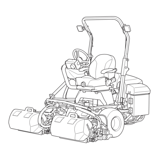
LM311 Product Overview Exterior B Names of Each Section Exterior A 5,6,7 1,2,3,4 733D0458 Names of Each Section_002 5738F1FC Hood Names of Each Section_001 Fuel tank Light Air cleaner Foldable ROPS Hydraulic tank Swisher holder Underseat cover Side cover Engine... - Page 21 LM311 Product Overview Exterior C Exterior D 834DE3D3 8CEE132A Names of Each Section_003 Names of Each Section_004 Fuel filter Operation panel Engine oil filter USB socket Hydraulic oil filter Steering wheel Steering height adjustment lever Steering angle adjustment lever Seat...
- Page 22 LM311 Product Overview Operation panel C8223688 Names of Each Section_005 Joystick Reel rotation switch 2WD/3WD selector switch Throttle lever Light switch Mower unit up switch Key switch Hour meter Water temperature gauge Pilot Lamps Mower unit CFE5FE19 Names of Each Section_006...
-
Page 23: Regulation Decals
LM311 Product Overview Description of Regulation Decals Regulation Decals Serial Number Plate Positions of Regulation Decals The serial number plate indicates the model and serial number of the machine. H,I,J 4ogipb-001 Serial Number Plate_001 Specification Decal (For EU) The Specification decal indicates the model and weight, etc. - Page 24 LM311 Product Overview CE Mark Year of Manufacture Decal (For EU) (For EU) CE mark indicates that the machine sold in The year of manufacture decal indicates the the EU nations complies with the EU year when this machine was manufactured.
- Page 25 LM311 Product Overview ROPS Caution Decal Recycle Decal ROPS caution decal describes the following Recycle Decal illustrates Recycle Mark in caution messages. accordance with local regulation. (For EU) ・ Replace damaged ROPS. Do not repair or revise. ・ y7wov5-001 Recycle Decal_001...
- Page 26 LM311 Product Overview Indicating Diesel Fuel Decal Spark Arrester Warning Decal (for USA) (For the State of California, USA) It indicates the fuel to be used. Spark arrester warning decal describes the Use low sulfur or ultra-low sulfur diesel fuel warning messages as required by California (sulfur-free diesel fuel).
-
Page 27: Safety Signs And Instruction Signs
Part numbers for decals that need to be Decal for operation 2 replaced are listed in the parts catalog. Fire prohibited decal Order them from a Baroness dealer or Hydraulic oil icon Kyoeisha. Diesel fuel decal Positions of Safety Decals and Instruction... -
Page 28: Description Of Safety Decals And Instruction Decals
LM311 Product Overview Description of Safety Decals and Instruction Decals Warning Apply the parking brake, stop the engine, Decal for Operation 2 remove the ignition key, and then leave the LM2400-0918Z0 machine. STICKER, OPERATION 2 100ECC69 2349A4A4 Decal for Operation 2_001 Decal for Operation 2_003 ... - Page 29 LM311 Product Overview Without ROPS: ・ Warning Danger Danger May cut your hand or leg - Keep hands and feet away from moving parts. Rollover - Do not work on slopes of 15 degrees or more. When you descend a slope, lower the mower units and then drive at low speed.
- Page 30 LM311 Product Overview Hydraulic Oil Icon Caution for High Temperatures Decal K4209000980 K4205001920 Hydraulic oil icon Decal, caution for high temperatures Read the Owner's Operating Manual. Caution High temperature - Do not touch. Otherwise, you will get burned. i77xz6-001 Hydraulic Oil Icon_001...
- Page 31 LM311 Product Overview Caution for Spouting Coolant Decal Decal on Prohibiting High Pressure Washing K4205001970 K4205002390 Decal, caution for spouting coolant Decal, prohibition of high pressure washing Do not wash with high pressure. Caution Caution for spouting coolant - Do not open while hot.
-
Page 32: Operation Decals
LM311 Product Overview Description of Operation Decals Operation Decals Operation Decal Positions of Operation Decals LM311--0508Z0 STICKER, OPERATION 8624B63B Operation Decal_001 Key Switch Mark ■ Key switch mark This indicates the key switch positions. STOP 534C4DBB Positions of Operation Decals_001... - Page 33 LM311 Product Overview Engine Rotation Decal 2WD - 3WD Selector Lever Decal ■ ■ Engine rotation decal 2WD - 3WD selector lever decal This indicates high/low speed of the engine This indicates the 2WD/3WD positions. rotation. F2815F02 kp2t9l-002 2WD - 3WD Selector Lever Decal_001 Engine Rotation Decal_001 ■...
- Page 34 LM311 Product Overview Reel Rotation Mark Decal of Indicating Reel Rotation ■ Reel rotation mark LM311--0510Z0 It illustrates Rotation/Stop of the reel cutter DECAL, INDICATING REEL ROTATION (cutting cylinder). It lists the dial settings for corresponding reel rotation speeds. ・...
- Page 35 LM311 Product Overview Lapping Switch Decal BACKWARD Decal K4203001580 K4203001440 Decal, lapping switch Decal, BACKWARD This indicates ON/OFF switching of back This indicates backward travel. lapping operation. BACKWARD kqca3e-002 v57o51-004 BACKWARD Decal_001 Lapping Switch Decal_001 Reel Rotation Decal Reverse rotation (back lapping...
- Page 36 LM311 Product Overview Groomer Indication Mark Note: Depending on the specifications, this function may not be available. K4203001120 DECAL, GROOMER INDICATION It illustrates the changeover of rotational direction of the groomer. Normal Stop Reverse n54vge-001 Groomer Indication Mark_001 Normal rotation...
-
Page 37: Description Of Functions
LM311 Description of Functions Joystick ..........Page 4-2 Reel Rotation Switch ......Page 4-2 2WD/3WD Selector Switch ....Page 4-3 Throttle Lever .........Page 4-3 Light Switch ........... Page 4-3 Mower Unit Up Switch ......Page 4-4 Key Switch ..........Page 4-4 USB Socket .......... -
Page 38: Joystick
LM311 Description of Functions When the reel rotation switch is set to the Joystick "Rotation" position, the reel cutters will rotate. When the reel rotation switch is set to the Important "Rotation" position, the reel cutters will rotate or stop in sync with the up and down motion Even if the reel rotation switch is set to the of the mower units. -
Page 39: 2Wd/3Wd Selector Switch
LM311 Description of Functions 2WD/3WD Selector Switch Caution In case of 2WD/3WD model, travel in 2WD mode on steep downward slopes, wet road surface or downward slopes of wet lawn since traveling there in 3WD mode is dangerous. Otherwise, the rear tire going into a skid may cause loss of traveling control. -
Page 40: Mower Unit Up Switch
LM311 Description of Functions Mower Unit Up Switch Warning The reel cutter rotates while holding down the mower unit up switch when the reel rotation switch is set to the "Rotation" position. Set the reel rotation switch to the "Stop"... -
Page 41: Usb Socket
LM311 Description of Functions USB Socket Steering Height Adjustment Lever The position of the steering arm can be adjusted Important with the steering height adjustment lever. Do not use the USB socket in rainy weather to Tilt the steering height adjustment lever to the avoid malfunction of devices. -
Page 42: Seat Forward Tilt Angle Adjustment Lever
LM311 Description of Functions Seat Forward Tilt Angle Adjustment Lever Tilt the seat forward tilt angle adjustment lever and adjust the forward tilt angle of the seat to three levels. Tilt the lever and release it where the seat is locked. -
Page 43: Reel Forward/Reverse Switch
LM311 Description of Functions Reel Forward/Reverse Switch Reel Rotation/Stop Switching Lever Important Caution Do not switch between "Forward" and Before operating the reel rotation/stop "Reverse" while the reel cutter (cutting switching lever, be sure to set the reel rotation cylinder) is rotating. -
Page 44: Groomer Clutch Lever
LM311 Description of Functions Groomer Clutch Lever Swisher Holder Note: Caution Depending on the specifications, this function may not be available. Be careful not to hit your eyes with swisher pole when it is in the swisher holder. Caution Swisher pole can be stored in this holder for Shift the lever for setting to the arbitrary transport. -
Page 45: Hour Meter
LM311 Description of Functions Hour Meter Pilot Lamps The hour meter indicates the accumulated Charge Lamp operation time of the engine. The charge lamp is the left pilot lamp located The number in red figures on a white in the operation panel. -
Page 46: Fuel Gauge
LM311 Description of Functions Fuel Gauge Thermo-Start Lamp The thermo-start lamp is the middle pilot lamp The fuel gauge is located on the fuel tank. located in the operation panel. This instrument indicates the quantity of fuel When the ignition key is set to the "GLOW"... -
Page 47: Warning Mechanisms
LM311 Description of Functions Warning Mechanisms Warning Buzzer Overheat warning buzzer When the water temperature inside the engine exceeds 115 degrees Celsius (239 °F), the buzzer sounds. (intermittent tone) When the buzzer sounds, stop the engine immediately, inspect the machine and perform any necessary maintenance. -
Page 48: Warning Mechanisms
LM311 Description of Functions Page 4-12 Warning Mechanisms... -
Page 49: Handling Instructions
LM311 Handling Instructions Operations Before Service ....Page 5-2 Opening and Closing of Hood ....Page 5-2 Opening and Closing of Underseat Cover ............. Page 5-2 Opening and Closing of Radiator Cover ............. Page 5-3 Opening and Closing of Side Cover ..Page 5-3 Inspection Before Use ......Page 5-4... -
Page 50: Operations Before Service
LM311 Handling Instructions Press the hood lightly and lock it with the Operations Before Service bolt. The following sections describe the preparatory Opening and Closing of Underseat Cover works required before performing the services including inspection, adjustment, cleaning. Caution maintenance and repair. -
Page 51: Opening And Closing Of Radiator Cover
LM311 Handling Instructions Opening and Closing of Radiator Cover Opening and Closing of Side Cover Important Important Do not open or close the radiator cover while Open or close the side cover while the the side cover is open. radiator cover is closed. -
Page 52: Inspection Before Use
LM311 Handling Instructions Check the engine oil level. Inspection Before Use The appropriate oil level should be between the upper and lower limit lines on the The purpose of the machine inspection is to: gauge. Prevent accidents ・ Prevent damage to the machine ・... - Page 53 LM311 Handling Instructions Fuel Supply Air Bleeding of Fuel System Warning Important Supply fuel before starting the engine. Be sure to tighten the air-bleeding plug except Do not remove the tank cap or supply fuel when air bleeding. while the engine is running or when the Otherwise, it may cause the engine stop.
- Page 54 LM311 Handling Instructions Make sure that the traveling pedal is Reserve tank neutral. FULL Set the ignition key to "START" position. Important Inspection of Air Cleaner In the case that there are still air bubbles in Make sure that there is no damage to the the fuel from air-bleeding plug even after 15 air cleaner.
-
Page 55: Main Vehicle
LM311 Handling Instructions Main Vehicle Warning Do not clean the battery with a dry cloth. Inspection of Hydraulic Oil Cleaning the battery with a dry cloth may The oil gauge is on the side of the hydraulic cause it to catch fire or explode due to static tank. - Page 56 LM311 Handling Instructions Inspecting the cable terminals UPPER LEVEL line If the connection between the battery LOWER LEVEL line terminals and vehicle's cable terminals are loose, tighten the nuts until the cable Inspection of Oil Cooler for Hydraulic Oil terminals are secured firmly.
- Page 57 LM311 Handling Instructions Switch the ignition key to the "OFF" Inspection of Brake Lever position. Check the brake lever moves smoothly. Inspection of Water Temperature Gauge Pull the brake lever. Check the water temperature is not Press the push button and release the damaged.
-
Page 58: Mower Unit
LM311 Handling Instructions Check to see whether or not the second Inspection of Liquid Leakage edge face (relief) remains at the point of reel cutter (cutting cylinder). Important Make sure that the welding between the After approximately 50 hours of operation,... -
Page 59: Adjustment Before Work
LM311 Handling Instructions Inspection of Groomer Note: Depending on the specifications, this function may not be available. Caution Wear gloves when touching edged tools to avoid cutting your hands. Make sure that the vertical blades are not A34C6A01 cracked. Adjustment of Seat Position_001... -
Page 60: Mower Unit
LM311 Handling Instructions Push the steering angle adjustment lever Adjustment of Steering Wheel Position forward to lock the steering angle. Warning Do not adjust the steering wheel position while traveling. Caution Make sure that the steering wheel position is securely locked. -
Page 61: Mounting/Dismounting
LM311 Handling Instructions Open the fuel cock. Wind rectifying plate Reel cover Reel cutter (Cutting cylinder) Reel cutter (cutting cylinder) rotates at low speed Reel cutter (cutting cylinder) rotates at high speed Mounting/Dismounting Mounting/Dismounting Procedure kou8ls-003 Procedure to Start Engine_001... -
Page 62: Parking And Stopping
LM311 Handling Instructions Shift the throttle lever to the "Low speed" Ignition key position, warm up the engine so that the needle points above "C" on the water temperature gauge. GLOW START Make sure that the glow plug is generating heat and the thermo-start lamp is turned on. -
Page 63: Move
LM311 Handling Instructions Move Cutting Work Traveling Procedure Cutting Work Warning Caution Set the reel rotation switch to the "Stop" Cutting work must be performed at an position except during mowing or backlapping appropriate speed for the site and location. -
Page 64: Reel Excess Discharge System
LM311 Handling Instructions Tilt the joystick to the "Down" position Start the engine. when the mower unit reaches the collar of Raise all mower units. the green. Shift the throttle lever to the "High Speed" Lower the mower units to start rotating the position. -
Page 65: Transporting
LM311 Handling Instructions Fasten the machine with ropes. Removing/Installing Grass Catcher For fastening the machine with ropes, use the following positions. Caution Front part of the machine: Use tow ・ Stop the engine before removing / installing hooks on the right and left side of the the grass catcher. -
Page 66: Cleaning After Use
LM311 Handling Instructions Start the engine. Cleaning of Radiator Raise the mower units. Travel backward slowly to unload the Caution machine from the truck or trailer. Do not touch the radiator or coolant during Cleaning After Use engine operation or immediately after the engine has been turned off. -
Page 67: Main Vehicle
LM311 Handling Instructions Unlock the rubber catches on the left and Important right of the oil cooler, and then tilt the oil cooler. Do not use solid objects, such as a spatula or screwdriver, or high-pressure water to clean the radiator and oil cooler. -
Page 68: Mower Unit
LM311 Handling Instructions Mower Unit Cleaning of Mower Unit Important While cleaning, do not allow water on the sealed parts of the reel shaft. (Avoid high- pressure water cleaning.) Otherwise, it may cause damage to the machine. Be sure to clean the mower unit after use. -
Page 69: Appended Table
LM311 Appended Table Tightening Torques ....... Page 6-2 Standard Tightening Torques ....Page 6-2 Principal Tightening Torques ....Page 6-5 Maintenance Schedule ......Page 6-9 Page 6-1... -
Page 70: Tightening Torques
LM311 Appended Table Tightening Torques Important Refer to the Tightening Torque table. Note that the Baroness product warranty may not apply to defects caused by incorrect or overtorque tightening, etc. Standard Tightening Torques Bolts and Nuts Important A number of bolts are used in each part of this machine. - Page 71 LM311 Appended Table General bolt Strength classification 4.8 Nominal diameter tib3yb-001 kgf-cm lb-in 3 - 5 30.59 - 50.99 26.55 - 44.26 7 - 9 71.38 - 91.77 61.96 - 79.66 14 - 19 142.76 - 193.74 123.91 - 168.17 29 - 38 295.71 - 387.49...
- Page 72 LM311 Appended Table Hydraulic Hose The tightening torques for union joints and union adaptors with parallel pipe threads (G, PF) are shown in the table below. A union joint or adaptor will not become loose or leak as long as it is tightened by the specified torque.
-
Page 73: Principal Tightening Torques
LM311 Appended Table Principal Tightening Torques Tightening Torque by Model LM311 Tighten the following bolts and nuts at the torque specified in the table. For thread locking adhesive, apply a middle strength thread locker (ThreeBond 1322 or equivalent anaerobic sealant). - Page 74 LM311 Appended Table Tightening torque Thread Location Code Part name locking kgf-cm lb-in adhesive Bolt, HT Brake Assy K0010080252 14 - 19 142.76 - 193.74 123.91 - 168.17 - M8-25 rear Bolt, HT 1835.46 - 1593.18 - wheel Brake drum K0010100302...
- Page 75 LM311 Appended Table Daily Check List ●・・・Inspect, adjust, supply, clean (first time) ○・・・Inspect, adjust, supply, clean ●・・・Replace (first time) △・・・Replace Maintenance Item Remarks Check engine oil ○ Check fuel ○ Check fuel filter ○ ...
- Page 76 LM311 Appended Table Maintenance Item Remarks Check reel cutter and bed knife ○ Check cover ○ Check groomer ○ Check mower unit appearance ○ Check bolts and nuts ...
-
Page 77: Maintenance Schedule
LM311 Appended Table Maintenance Schedule LM311 ●・・・Inspect, adjust, supply, clean (first time) ○・・・Inspect, adjust, supply, clean ▲・・・Replace (first time) △・・・Replace Remark Maintenance Item Open Open air valve cleaner every evacuator week or ○ ○ ... - Page 78 LM311 Appended Table Remark Maintenance Item Check radiator comes hoses and ○ ○ earlier clamp bands Clean fuel *1.*3 ○ ...
- Page 79 LM311 Appended Table Remark Maintenance Item Replace engine oil comes ▲ △ △ filter earlier cartridge Replace *2.*3 fuel filter △ ...
- Page 80 LM311 Appended Table Remark Maintenance Item Check hydraulic hose ○ (Moving part) Check electrical ● ○ ...
- Page 81 LM311 Appended Table Remark Maintenance Item (Moving △ part) Replace hydraulic hoses *1.*5 (Moving △ ...
- Page 82 LM311 Appended Table Remark Maintenance Item year whichev comes Clean and earlier, grease cam ○ ○ bush of the when...
- Page 83 ・ *1: Consult your local Baroness Dealer or local KUBOTA Dealer for this service. The items above (*2 marked) are registered as emission related critical parts by KUBOTA in the ・ U.S. EPA nonroad emission regulation. As the engine owner, you are responsible for the performance of the required maintenance on the engine according to the above instruction.
- Page 84 LM311 Appended Table Page 6-16 Maintenance Schedule...
- Page 85 1-26, Miyuki-cho, Toyokawa-city, Tel : +81 - 533 - 84 - 1390 Head Office Fax : +81 - 533 - 84 - 1220 Aichi-pref, 442-8530 JAPAN LM311---UM--GBZ/23L-00-S.K...
Need help?
Do you have a question about the LM311 and is the answer not in the manual?
Questions and answers