Baroness LM315GC Assembly And Installation Manual
Triple greens mower, kit modifying to 3wd
Hide thumbs
Also See for LM315GC:
- Service manual (199 pages) ,
- Owner's operating manual (115 pages) ,
- Technical information (5 pages)

Related Manuals for Baroness LM315GC


Summary of Contents for Baroness LM315GC
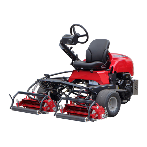
- Page 1 Triple Greens Mower LM315GC [KIT, MODIFYING TO 3WD] Assembly and installation manual 乗用3連グリーンモア LM315GC [3WD組替キット]取扱要領書 Vol.1 Serial No.#30001~...
- Page 2 The information described in this manual is subject to change without prior notice for improvement. When replacing parts, be sure to use genuine Baroness parts or parts designated by Kyoeisha. Note that the Baroness product warranty may not apply to defects caused by the use of parts from other companies.
- Page 3 This symbol is accompanied by the word "Danger," "Warning," or "Caution." All labels with this symbol describe important safety precautions, so please read such labels carefully and only operate the machine after you have understood them completely. Failure to adequately follow these safety precautions may cause an accident.
- Page 4 If necessary, use appropriate chain blocks, hoists, or a jack. If the machine is lifted up, ensure that it is supported by jack stands or appropriate blocks. When replacing parts or installing accessory parts, use genuine BARONESS parts. Never start the engine in a closed room. Doing so could cause carbon monoxide poisoning.
- Page 5 Installing Optional Equipment for the LM315GC LM315GC オプション取付要領 KIT, MODIFYING TO 3WD 3WD 組替キット部 Intended use: To easily climb to the green 用途:グリーンへ容易に登る為 Check that all parts are included. The following parts are included in the package. Should any part be missing or damaged, please contact the dealer you purchased it from.
- Page 6 BAND, PLASTIC CV-200B BOLT, M12-25 WASHER, SPRING M12 コンベックス TRCV-200W 12 ボルト 25 12S ワッシャ K4241000040 K0000120252 K0200120002 Qty:10 Qty:6 Qty:6 SWITCH ASSY, TOGGLE RUBBER, CAP WD1911 LAMP, WORKING LED RED トグルスイッチ ASSY ゴムキャップ WD1911 LED 表示灯(赤) LM315G-0531Z0 K4031000300 K3641000090 Qty:1 Qty:1 Qty:1...
- Page 7 Tightening torque 締付トルク Appropriate tightening torque [General bolts Strength class: 4.8] Required tightening torque Nominal diameter 適正締付トルク【一般ボルト 強度区分 4.8】 必要な締付トルク 呼び径 kgf-cm lb-in ○ 30.59~50.99 26.55~44.26 14~19 142.76~193.74 123.91~168.17 ○ 29~38 295.71~387.49 256.68~336.34 ○ 52~67 530.24~683.20 460.25~593.02 When tightening bolts, refer to the above table. We will not be held responsible for any damage resulting from improper or excessive tightening, etc.
- Page 8 Installation of modifying to 3WD kit 3WD 組替手順 Steps Illustrations Descriptions 手順 図 説明 Chock the front tire so that the vehicle will not move. Securely place the jack beneath the jack-up point indicated by the arrow, and then raise it until the tire lifts off the ground.
- Page 9 Steps Illustrations Descriptions 手順 図 説明 Reverse the removing procedure to install the wheel mounting plates (A) of the rear wheel part Assy (3WD) (1) onto the vehicle. Be careful not to damage the solenoid valve (B). 3WD 後輪部 Assy (1)のタイヤ取付け板(A)を、取外し た逆の手順で本体に取付けます。...
- Page 10 Steps Illustrations Descriptions 手順 図 説明 Carefully peel the tape off the bulging area of the main harness, and then disconnect the connectors. メインハーネスの膨らんだ部分のテープを丁寧にに剥 がし、コネクタを取出します。 Follow the steps below to install the solenoid valve onto the holes (A) in the frame. フレームの穴(A)に、以下の手順でソレノイドバルブ...
- Page 11 Steps Illustrations Descriptions 手順 図 説明 The arrow points toward the front of the vehicle. Remove the female screw cap (C) from the elbow (B) of the manifold (A), and then connect and tighten the hydraulic hose from the P port of the solenoid valve. Since the hydraulic hose connected to the solenoid valve is temporarily tightened, check for twists in the hose, and then tighten the hydraulic hose connector at the solenoid valve.
- Page 12 Steps Illustrations Descriptions 手順 図 説明 The routing diagram shows the hydraulic hose (A) from the P port of the solenoid valve and the hydraulic hose (B) from the B port. The hydraulic hose (C) will be connected to the hydraulic oil filter.
- Page 13 Steps Illustrations Descriptions 手順 図 説明 Install the elbow (5) onto the hydraulic oil filter. Install the 90 deg elbow (6) onto the elbow (5). Connect the hydraulic hose (A) from the T port of the solenoid valve (hydraulic hose (C) in step 14) to the 90 deg elbow (6).
- Page 14 Steps Illustrations Descriptions 手順 図 説明 Remove the plug (B) from the hydraulic tank (A). 油圧タンク(A)からプラグ(B)を取外してください。 After removing the plug from the hydraulic tank (A), remove the sealing tape residue (C) from the connecting portion (B) and clean the threaded portion so that the tape residue will not enter the hydraulic system.
- Page 15 Steps Illustrations Descriptions 手順 図 説明 Remove the grommet (A) of the operation panel. Do not reuse the grommet (A). 操作パネルのグロメット(A)を取外してください。 グロメット(A)は再使用しません。 From the toggle switch (10), remove the nut (B) for installing the toggle switch onto the operation panel. The nut (B), wave washer (A) and rubber cap (11) will be used to install the toggle switch onto the operation panel.
- Page 16 Steps Illustrations Descriptions 手順 図 説明 The connection diagram shows the harness (A) and the terminals (B). Reverse the removing procedure to install the operation panel cover. ハーネス(A)と各端子(B)の接続図です。 取外しの逆の手順で、操作パネルカバーを取付けてく ださい。 Connect the coupler (A) from the main harness to the coupler (B) from the solenoid valve.
- Page 17 Steps Illustrations Descriptions 手順 図 説明 Move the tire left and right (direction of the arrow). Check that the tire moves smoothly without the hydraulic hoses (A) interfering with the vehicle. タイヤを左右(矢印方向)に動かしてください。 油圧ホース(A)が本機に干渉せず、スムーズにタイヤ が動くことを確認してください。 Since the speed will decrease when cutting grass after the 3WD-modifying kit has been installed, adjust the speed.
- Page 18 Steps Illustrations Descriptions 手順 図 説明 Make adjustments with the reel unit raised. The standard speed of a machine with an engine rpm of 3,000 rpm, the reel rotation switch turned "ON" and the traveling pedal depressed is 10 m in approximately 6 seconds (6 km/h).
- Page 19 Head Office 1-26, Miyuki-cho, Toyokawa, Tel : (0533) 84 - 1390 Fax : (0533) 89 - 3623 Aichi-Pref. 442-8530 Japan. 442 - 8530 TEL (0533) 84 - 1221 1 - 26 FAX (0533) 84 - 1220 LM315GC-AM06GBZ/14C-00-KES...
Need help?
Do you have a question about the LM315GC and is the answer not in the manual?
Questions and answers