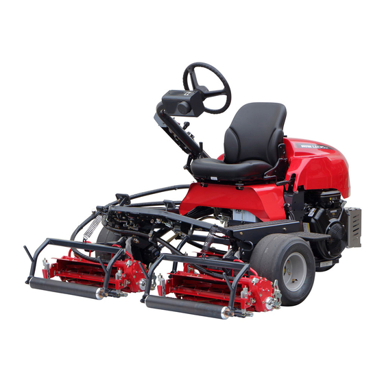
Baroness LM315GC Owner's Operating Manual
Riding greens mower, diesel
Hide thumbs
Also See for LM315GC:
- Service manual (199 pages) ,
- Owner's operating manual (86 pages) ,
- Assembly and installation manual (19 pages)

Related Manuals for Baroness LM315GC


Summary of Contents for Baroness LM315GC
- Page 1 Riding Greens Mower (Diesel Model) Owner's Operating Manual Serial No. LM315GC:31902- "Required reading" Read this manual before using the machine. Original Instructions Ver.4.4...
- Page 2 LM315GC Regulations California Proposition 65 California Spark Arrester (For California, USA) (For California, USA) Warning WARNING: Operation of this equipment may create Operating, servicing and maintaining sparks that can start fires around dry a passenger vehicle or off-road vegetation. vehicle can expose you to chemicals A spark arrester may be required.
- Page 3 LM315GC Greeting Thank you for purchasing the Baroness product. QR Code This manual describes the proper handling, adjustment, and inspection of your product. A QR code label is affixed on the machine. We hope you will use the product safely, and take advantage of its best performance.
- Page 4 The operator is responsible for operating the product properly and safely. Maintenance service for this machine should be performed by a mechanic with expertise. If you have any questions concerning maintenance or genuine parts, please contact a Baroness dealer or Kyoeisha.
- Page 5 When replacing parts, be sure to use genuine Baroness parts or parts designated by Kyoeisha. Note that the Baroness product warranty may not apply to defects caused by the use of parts from other companies. Prior to use, carefully read the following manuals to thoroughly understand the contents for safe and correct operation.
- Page 6 LM315GC Introduction...
-
Page 7: Table Of Contents
LM315GC Contents Safety .............. Page 1-1 Greasing ............Page 6-3 Lubrication ............. Page 6-8 Safe Operating Practices .......Page 1-2 Operations Before Maintenance ....Page 6-9 Disposal ............Page 2-1 Adjustment and Replacement ......Page 6-10 Storage ............Page 6-31 Recycle and Waste Disposal ......Page 2-2 Repair ..............Page 7-1... - Page 8 LM315GC Contents...
-
Page 9: Safety
LM315GC Safety Safe Operating Practices ...... Page 1-2 Training ..........Page 1-2 Preparation ..........Page 1-2 Operation ..........Page 1-3 Maintenance .......... Page 1-4 Storage ..........Page 1-5 Page 1-1... -
Page 10: Safe Operating Practices
LM315GC Safety Failure to adequately follow these safety Never allow children or people unfamiliar precautions may cause an accident resulting in with these instructions to use or service the injury or death. machine. Local regulations may restrict the age of the... -
Page 11: Operation
LM315GC Safety Add fuel before starting the engine. Never operate while people, especially Never remove the cap of the fuel tank or children, or pets are nearby. add fuel while the engine is running or Only operate in good light, keeping away when the engine is hot. -
Page 12: Maintenance
LM315GC Safety Do the following before leaving the Implement the following work before operator's position. adjusting, cleaning or repairing. Stop on level ground. Stop the machine on level ground. Disengage the all drives. Disengage drive to the cutting unit(s). Set the parking brake. -
Page 13: Storage
LM315GC Safety When checking the hydraulic circuit for Swallowing engine coolant can cause injury pinhole leaks or oil leakage from nozzles, do or death; keep out of reach from children and not use your hands. pets. Use items such as paper or corrugated cardboard to find leakage points. - Page 14 LM315GC Safety Page 1-6 Safe Operating Practices...
-
Page 15: Disposal
LM315GC Disposal Recycle and Waste Disposal ....Page 2-2 About Recycle ........Page 2-2 About Waste Disposal ......Page 2-2 Page 2-1... -
Page 16: Recycle And Waste Disposal
LM315GC Disposal Recycle and Waste Disposal About Recycle Recycling battery etc. is recommended for environmental conservation and economical use of resources. It may be required by local laws. About Waste Disposal Make sure that waste generated when servicing or repairing the machine is disposed of in accordance with local regulations. -
Page 17: Product Overview
LM315GC Product Overview Specifications ........Page 3-2 Specifications .........Page 3-2 Sound Pressure Level ......Page 3-4 Sound Power Level ....... Page 3-4 Vibration Level ........Page 3-4 Carbon Dioxide (CO2) Emissions ..Page 3-4 Names of Each Section ......Page 3-5 Regulation Decals ........Page 3-5... -
Page 18: Specifications
LM315GC Product Overview Specifications Specifications Model LM315GC Name Riding Greens Mower Type for greens for tees for fields Total length 239 cm 94.09 in ← ← ← ← Total width 172 cm 67.72 in ← ← ← ← Dimensions Steering 132 - 141 51.97 -... - Page 19 LM315GC Product Overview 1.5 - 18.0 0.059 - 6.0 - 20.0 0.236 - 10.0 - 40.0 0.394 - Operating height (Mowing height) 0.709 in 0.787 in 1.575 in Number of Blades 9, 11 ← HST 2WD [3WD Traveling ← ←...
-
Page 20: Sound Pressure Level
LM315GC Product Overview Sound Pressure Level Sound Pressure Level This machine was confirmed to have a continuous A-weighted sound pressure level of 87 dB by measuring identical machines in accordance with the procedure specified in ISO 5395-1:2013. Sound Power Level... -
Page 21: Names Of Each Section
LM315GC Product Overview Names of Each Section Regulation Decals Positions of Regulation Decals I,J,K B,C,D quwxcl-124 Names of Each Section_001 9754DA64 Operation panel Positions of Regulation Decals_001 Steering wheel Serial number plate Seat Specification decal Underseat cover CE Mark Mower pedal... -
Page 22: Description Of Regulation Decals
LM315GC Product Overview Description of Regulation Decals UKCA Mark Serial Number Plate (For UK) UKCA mark indicates that the machine sold in The serial number plate indicates the model the UK complies with the UK requirements. and serial number of the machine. - Page 23 LM315GC Product Overview Year of Manufacture Decal Battery Capacity Decal (For EU/UK) (For Europe) The year of manufacture decal indicates the The battery capacity decal indicates the year when this machine was manufactured. capacity by 20HR and CCA. YEAR OF...
- Page 24 LM315GC Product Overview Battery Danger Decal Spark Arrester Warning Decal (For USA) (For the State of California, USA) Battery Danger Decal describes handling Spark arrester warning decal describes the precautions for battery. warning messages as required by California Public Resources Code.
-
Page 25: Safety Signs And Instruction Signs
Caution for slopes (3WD) decal Part numbers for decals that need to be replaced are listed in the parts catalog. Caution for spouting coolant decal Order them from a Baroness dealer or Caution to noise decal Kyoeisha. Decal on reading owner's operating... - Page 26 LM315GC Product Overview Caution to Mutilation Decal Hydraulic Oil Icon K4205001600 K4209000980 DECAL, CAUTION TO MUTILATION Hydraulic oil icon Read the Owner's Operating Manual. Warning May cut your hand or leg - Stop the cutter rotation and engine. Otherwise you may get injured.
- Page 27 LM315GC Product Overview Caution for High Temperatures Decal Caution Slope Decal K4205001920 K4205002040 Decal, caution for high temperatures Decal, caution slope Caution Caution High temperature - Do not touch. Otherwise, Rollover - Do not work on slopes of 15 you will get burned.
- Page 28 LM315GC Product Overview Caution for Slopes (3WD) Decal Caution to Noise Decal K4205002080 K4205002090 Decal, caution for slopes (3WD) Decal, caution to noise (3WD spec model only) Warning Rollover - Do not switch between 2WD and 3WD while traveling on downward slopes.
-
Page 29: Operation Decals
LM315GC Product Overview Operation Decals Reel rotation/stop mark Engine rotation mark Positions of Operation Decals Mower unit Up/Down decal Key switch mark Mower unit up-switch (with reel excess discharge system) mark 2WD/3WD changeover decal Light switch decal FORWARD Decal BACKWARD Decal... - Page 30 LM315GC Product Overview Engine Rotation Mark Key Switch Mark Engine rotation mark Key switch mark This indicates low/high speed of engine This indicates the key switch positions. rotation. STOP rcyo1p-002 kp2t9l-006 Key Switch Mark_001 Engine Rotation Mark_001 Low speed GLOW...
- Page 31 LM315GC Product Overview 2WD/3WD Changeover Decal FORWARD Decal Note: K4203001430 Depending on the specifications, this function Decal, FORWARD may not be available. This indicates forward travel. K4203001620 Decal, shifting 2WD/3WD This indicates 2WD/3WD changeover. FORWARD kqca3e-001 FORWARD Decal_001 BACKWARD Decal...
- Page 32 LM315GC Product Overview Position Decal LM315GC1418Z0 Decal, position This indicates changeover of High/Low speed of reel cutter rotation and back lapping rotation. f3a6yr-001 Position Decal_001 High speed Low speed Back lapping Mower Unit Reel Rotation Changeover Decal K4203001550 Sticker, rotating direction...
-
Page 33: Description Of Functions
LM315GC Description of Functions Light Switch ........... Page 4-2 Throttle Lever .........Page 4-2 Mower Pedal ...........Page 4-2 Joystick ..........Page 4-3 Mower Unit Up Switch ......Page 4-3 Up Switch (with Reel Excess Discharge System) ........ Page 4-3 2WD/3WD Selector Switch ....Page 4-4 Reel Rotation Switch ...... -
Page 34: Light Switch
LM315GC Description of Functions Light Switch Mower Pedal Note: Caution Depending on the specifications, this function may not be available. Do not keep depressing the mower pedal after The light switch is located in the operation an operation. panel. It may cause malfunction. -
Page 35: Joystick
LM315GC Description of Functions Joystick Mower Unit Up Switch Up Switch (with Reel Excess Discharge Note: System) Depending on the specifications, this function may not be available. Warning Important The reel cutter rotates while holding down the Even if the reel rotation switch is set to the up switch when the reel rotation switch is set "Rotation"... -
Page 36: 2Wd/3Wd Selector Switch
LM315GC Description of Functions Reel excess discharge system ・ Important Reel excess discharge system is the function to remove clippings inside the reel cutter by When switching between 2WD and 3WD rotating the reel cutter with the up switch on... -
Page 37: Reel Rotation Switch
LM315GC Description of Functions When the reel rotation switch is set to the Reel Rotation Switch "Rotation" position, the reel cutters (cutting cylinders) will rotate or stop in sync with the up Warning and down motion of the mower units. When the... -
Page 38: Transmission Selector Lever
Traveling Pedal Important Caution For the LM315GC (for fields), normally cut When the machine is traveling at a high with the lever set to the "Low speed" position. speed, it will not stop immediately after you take your foot off the traveling pedal. -
Page 39: Parking Brake Lever
LM315GC Description of Functions Broom Holder Forward pedal Reverse pedal Note: Parking Brake Lever Depending on the specifications, this function may not be available. Broom can be stored in this holder for transport. Caution Never park the machine on a slope. -
Page 40: Instruments On The Operation Panel
LM315GC Description of Functions If the water temperature gauge indicates a Instruments on The Operation Panel level close to "H" during operation, the machine is overheated. Remove the load from the engine, idle the machine for five minutes, stop the engine, and then inspect the machine and perform any necessary maintenance. -
Page 41: Fuel Gauge
LM315GC Description of Functions Fuel Gauge Thermo-Start Lamp The thermo-start lamp is the middle pilot lamp The fuel gauge is located on the fuel tank. located in the operation panel. This instrument indicates the quantity of fuel When the ignition key is set to the "GLOW"... -
Page 42: Warning Mechanisms
LM315GC Description of Functions Warning Mechanisms Warning Buzzer Overheat warning buzzer If the water temperature inside the engine exceeds 105 degrees Celsius, a buzzer will sound. (intermittent tone) When the buzzer sounds, stop the engine immediately, and then inspect the machine and perform any necessary maintenance. -
Page 43: Handling Instructions
LM315GC Handling Instructions Operations Before Service ....Page 5-2 Start/Stop of Engine ......Page 5-17 Opening and Closing of Hood ....Page 5-2 Procedure to Start Engine ....Page 5-17 Opening and Closing of Underseat Procedure to Stop Engine ....Page 5-19 Cover ............. -
Page 44: Operations Before Service
LM315GC Handling Instructions Adjust the steering wheel arm to the lowest Operations Before Service position. "Adjustment of Steering Wheel Position" The following sections describe the preparatory (Page 5-17) works required before performing the services Slide the seat forward and rotate the lock including inspection, adjustment, cleaning. -
Page 45: Inspection And Cleaning
LM315GC Handling Instructions Rotate the lock lever 90 degrees clockwise Check to see whether or not the second to fix the underseat cover. edge face (relief) remains at the point of reel cutter (cutting cylinder). Make sure that the welding between the reel cutter (cutting cylinder) and the disc has not come off. -
Page 46: Groomer
LM315GC Handling Instructions Make sure that there is no play in the fit of Groomer the bearing and the housing. Inspection of Groomer Make sure that there is no play in the brush shaft. Note: Scraper Depending on the specifications, this function may not be available. -
Page 47: Radiator
LM315GC Handling Instructions Cleaning of Dust-Proof Mesh Important Do not use solid objects, such as a spatula or Important screwdriver, or high-pressure water to clean the radiator or oil cooler. An unclean dust-proof mesh may cause Otherwise, special fins or tubes may be overheating or damage to the engine. -
Page 48: Coolant
LM315GC Handling Instructions Coolant Caution The radiator cap is pressurized. Inspection of Coolant If you remove the radiator cap while the engine is overheated, hot steam will burst out, Caution possibly resulting in burns. Do not touch the radiator or coolant during... -
Page 49: Hydraulic Oil
LM315GC Handling Instructions Important Use Shell Tellus S2M46 (or equivalent) as hydraulic oil. In case of an equivalent, consult Characteristics of Hydraulic Oil and use hydraulic oil whose characteristics are superior to those of the specific hydraulic oil. Especially regarding kinematic viscosity and... -
Page 50: Hydraulic Hoses
LM315GC Handling Instructions Make sure that the air cleaner element is Tank cap not contaminated. Oil gauge Start the engine, raise and lower the mower units, and turn the steering wheel left and right. Move forward and reverse repeatedly several times. -
Page 51: Battery
LM315GC Handling Instructions Cleaning the exterior Air cleaner element Use a wet cloth for cleaning. Clip Inspect the vent plugs or vent holes on the Air cleaner cap side of the battery, and if they are blocked Air cleaner body by dirt wash them with water to remove the blockage. - Page 52 LM315GC Handling Instructions Inspecting the electrolyte level and refilling Danger Danger Warning When you supply battery fluid, wear protective Do not allow the battery fluid level to become garments and safety glasses, etc. lower than the LOWER LEVEL (minimum fluid level line).
-
Page 53: Electrical Wiring
LM315GC Handling Instructions Electrical Wiring Belt Inspection of Electrical Wiring Inspection of Belt Warning Important Electrical short circuit will cause fire, electrical The engine must be stopped when the belt is leakage and malfunction of electrical inspected. equipments. Important Make sure that there is no defacement in wires and terminals. -
Page 54: Around The Engine
LM315GC Handling Instructions Position the machine so that the engine will Around The Engine be level, then insert the oil level gauge all the way to check the oil level. Inspection of Engine-Associated Parts Caution Perform operations after the engine and other parts have sufficiently cooled. -
Page 55: Fuel
LM315GC Handling Instructions Fuel Supply of Engine Oil For details on handling the engine, please Inspection of Fuel Quantity refer to the separate Engine Handling Manual. With the machine on a level surface, observe Important the fuel gauge on the fuel tank to check the fuel level. - Page 56 LM315GC Handling Instructions Fuel Supply Air Bleeding of Fuel System Warning Important Supply fuel before starting the engine. Be sure to tighten the air-bleeding plug except Never remove the tank cap or supply fuel when air bleeding. while the engine is running.
-
Page 57: Fuel Filter
LM315GC Handling Instructions Make sure that the traveling pedal is Bolts and Nuts neutral. Inspection of Bolts and Nuts Set the ignition key to "START" position. Important Important In the case that there are still air bubbles in The bolts and nuts may be loosened at the the fuel from air-bleeding plug even after 15 earlier stage of the use. -
Page 58: Adjustment Before Work
LM315GC Handling Instructions Make sure that there is no damage to the The seat can be adjusted to one of three grass catcher. levels by pulling up the forward tilt angle adjustment lever. Make sure that there is no interference to moving parts due to deformation of the grass catcher. -
Page 59: Start/Stop Of Engine
LM315GC Handling Instructions Adjustment of Steering Wheel Position Warning Since it is dangerous, do not adjust the steering wheel while traveling. Caution Be sure the steering wheel position is securely locked. 75uxaw-007 It may result in an unexpected accident if it Adjustment of Steering Wheel Position_002 becomes loose while traveling. - Page 60 LM315GC Handling Instructions Sit on the seat. Ignition key Make sure that the parking brake is applied. Set the reel rotation switch to the "Stop" position. GLOW START Make sure that the glow plug is generating heat and the thermo-start lamp is turned on.
-
Page 61: Parking And Stopping
LM315GC Handling Instructions Move the throttle lever to the "Low speed" Move position, and then warm up the engine so that the needle points above "C" on the Traveling Procedure water temperature gauge. Warning Set the reel rotation switch to the "Stop"... -
Page 62: Cutting Work
LM315GC Handling Instructions Depress the mower pedal when the Cutting Work mower unit reaches the collar of the green. Cutting Work Lower the mower units to start rotating the reel cutters (cutting cylinders). Warning Note: Set the reel rotation switch to the "Stop"... -
Page 63: Transporting
LM315GC Handling Instructions Brush the clippings accumulated on the Apply the parking brake. bracket. Stop the engine. At the time the clippings comes inside of Lift up the grass catcher and remove it. the reel cutter. Install the grass catchers. - Page 64 LM315GC Handling Instructions Page 5-22 Transporting...
-
Page 65: Maintenance
LM315GC Maintenance Precautions for Maintenance ....Page 6-2 Storage ..........Page 6-31 Jacking Up The Machine .......Page 6-2 Long-Term Storage ......Page 6-31 About Jacking Up The Machine .....Page 6-2 Jack-Up Points ........Page 6-2 Greasing ..........Page 6-3 About Greasing ........Page 6-3 Greasing Points ........ -
Page 66: Precautions For Maintenance
First, learn well the operations you plan to perform. Important Use tools appropriate for each operation. Important Use Baroness genuine parts for replacement and accessories. Our product warranty may be void if you use non-genuine parts for replacement or accessories. -
Page 67: Greasing
LM315GC Maintenance Front left frame rwyt62-054 Jack-Up Points_003 Engine mount frame 59A9FEC9 Greasing Points_001 rwyt62-055 Jack-Up Points_004 No. of Greasing Greasing Location greasing schedule points About Greasing Mower unit Mower arm fulcrum Since there may be adhesion or damage due... - Page 68 LM315GC Maintenance Mower unit Front roller Each mower unit has 14 points. Note: Depending on the specifications, this function may not be available. Split roller has no greasing point. Left side 8bq62b-387 Greasing Points_002 Left frame 8bq62b-388 Greasing Points_005 Right side...
- Page 69 LM315GC Maintenance Right side Front mower unit There are two greasing points on each mower unit. 8bq62b-391 Greasing Points_008 Groomer 8bq62b-394 Note: Greasing Points_011 Depending on the specifications, this Rear mower unit function may not be available. There are two locations.
- Page 70 LM315GC Maintenance Neutral position area Traveling pedal shaft fulcrum 8bq62b-397 8bq62b-401 Greasing Points_014 Greasing Points_018 Rear wheel pivot Rear wheel brake lever shaft 8bq62b-398 8bq62b-402 Greasing Points_015 Greasing Points_019 Mower pedal shaft fulcrum Flexible wire edge There is one greasing point on each flexible wire.
- Page 71 LM315GC Maintenance Central part Important There are three greasing points. Lack of grease in the flexible wire may cause damage to it. Grease according to the maintenance schedule. The inner cable is a strand wire. Lack of grease in the strand wire may cause friction inside it resulting in damage due to abnormal heat generation.
-
Page 72: Lubrication
LM315GC Maintenance Lubricating Points Apply lubricant at the following locations every 50 hours of operation. D2FFA508 Greasing Points_025 Cam bush There is one greasing point on each right and left side. Apply 0.5 g(0.001 lb)of grease to the outer periphery of the cam bush pipe according to the maintenance schedule. -
Page 73: Operations Before Maintenance
LM315GC Maintenance Mower up/down cylinder spherical bearing Operations Before Maintenance There is one point each on the mower up/ down cylinders. Removing and Installing of Mower Unit Rear mower unit Removing the mower unit Remove the clip which fixes the mower unit and flexible wire. -
Page 74: Adjustment And Replacement
LM315GC Maintenance If the reel cutter (cutting cylinder) is too ・ Adjustment and Replacement tight to turn: Tighten (rotate clockwise) the cutter Adjustment of Blade Engagement adjustment nut to reduce the contact pressure between the reel cutter (cutting Caution cylinder) and the bed knife (bottom blade). - Page 75 LM315GC Maintenance Cutting Height and Blade Thickness of Bed Knife (Bottom Blade) Important The recommended minimum cutting heights are based on those of common greens. They may vary according to the green conditions and machine specifications. If the green undulation is hard, set it a little bit higher in order not to damage the green surface.
- Page 76 Blade)_001 Bed knife (bottom blade) Thickness of blade Adjustment of Rear Roller LM315GC (for greensmowing) You can adjust the rear roller by six stages. Attach the rear roller in a position that suits your work requirements within the cutting height range.
- Page 77 LM315GC Maintenance LM315GC (for tee mowing) LM315GC (for field mowing) You can adjust the rear roller by eight You can adjust the rear roller by eight stages. stages. Attach the rear roller in a position that Attach the rear roller in a position that...
-
Page 78: Adjustment Of Groomer
LM315GC Maintenance Adjustment of Front Roller Bed knife (bottom blade) Cutting height setting screw Set the slide caliper to the required cutting Cutting height gauge height, adjust the neck position of the Cutting height cutting height setting screw of the cutting... -
Page 79: Adjustment Of Rear Scraper (Wire Type)
LM315GC Maintenance Front groomer Cutting height Groomer setting screw Cutting height gauge Cutting height gauge Cutting height setting screw Front roller Operating height Front roller Rear roller Loosen the nuts fixing the right and left Bed knife (bottom blade) groomer adjustment bolts. -
Page 80: Adjustment Of Cutter Adjustment Spring
LM315GC Maintenance Adjustment of Cutter Adjustment Spring If the diameter of the reel cutter (cutting cylinder) becomes smaller, adjust the cutter adjustment spring. Adjust the blade engagement. Loosen the pipe with cutter adjusting screw, and then adjust the length of the spring coil to approximately 30.0 mm (1.181 in). -
Page 81: Back Lapping
Abrasive [Back lapping powder cylinder) and the bed knife (bottom blade) at an angle of 90 degrees. Then, rotate the reel mixed with oil; or gel compound (Baroness cutter (cutting cylinder) counter-clockwise genuine abrasive)], Brush. (when you face the mower unit from the left) to check the sharpness of the blades. -
Page 82: Sharpening Of Reel Cutter (Cutting Cylinder)
(Never apply to shape. blunt areas.) For sharpening the reel cutter (cutting cylinder), contact your dealer or Baroness Let the reel rotate for a while and, when unless you have a grinding machine. contact noise is no longer heard, return the reel rotation switch to the "Stop"... - Page 83 LM315GC Maintenance Sharpening is necessary when the reel Usage limit cutter (cutting cylinder) reaches a condition Dimension B Dimension B described below. (Distance (Distance Dimension A Dimension A When the sharpening width (length of from blade from blade contacting surface of bed knife (bottom...
-
Page 84: Replacement Of Reel Cutter (Cutting Cylinder)
LM315GC Maintenance Replacement of Reel Cutter (Cutting Cylinder) Caution Both the reel cutter (cutting cylinder) and the bed knife (bottom blade) are edged tools. Handle them carefully, since they could cut your hands and feet. Caution Wear gloves when touching edged tools to avoid cutting your hands. -
Page 85: Replacement Of Bed Knife (Bottom Blade)
LM315GC Maintenance Replacement of Bed Knife (Bottom Blade) Attaching Reel Cutter (Cutting Cylinder) Caution Caution Both the reel cutter (cutting cylinder) and the Both the reel cutter (cutting cylinder) and the bed knife (bottom blade) are edged tools. bed knife (bottom blade) are edged tools. -
Page 86: Replacement Of Tires
LM315GC Maintenance High-speed-steel-tipped blade Installing front tires Replace the bed knife (bottom blade) before it Important no longer has a tip. Tighten the bolts in the tightening order (crosswise). Important Tighten the wheel mounting bolts on the specified torque by using a torque wrench. - Page 87 LM315GC Maintenance Remove the bolts. Remove the bolts. 75uxaw-005 75uxaw-005 Change of Rear Tire_002 Change of Rear Tire_004 Bolt Bolt Remove the tire from the wheel mounting Remove the tire from the wheel mounting base. base. Removing the rear tire from the 3WD...
-
Page 88: Adjustment Of Belt Tension
LM315GC Maintenance Adjust belt tension so that the deflection may Adjustment of Belt Tension be 13±2 mm (0.51±0.08 in) when applying 55.0 N (5.5 kgf) load right in the middle of Warning pulleys. Be sure to stop the engine before adjusting the belts. -
Page 89: Change Of Coolant
LM315GC Maintenance Loosen the nut to adjust the length of the Important spring is 50.0 mm (1.969 in). When changing the coolant, be sure to mix clean water (soft water) and antifreeze (long- life coolant), and then pour it into the radiator and reserve tank. -
Page 90: Change Of Hydraulic Oil
LM315GC Maintenance Remove the radiator cap and drain the Stop the engine, and then allow the radiator coolant. to cool. Check if the coolant level in the reserve tank is between "FULL" and "LOW", and then supply coolant if necessary. -
Page 91: Change Of Hydraulic Oil Filter
LM315GC Maintenance Follow the steps below to remove the old oil. Start the engine, raise and lower the mower units, and turn the steering wheel left and Start and run the engine to warm up the right. oil. Move forward and reverse repeatedly On a level surface, lower the mower units, several times. -
Page 92: Change Of Air Cleaner Element
LM315GC Maintenance Lightly coat the packing of the new filter Change of Engine Oil cartridge with hydraulic oil, and then install the cartridge. Caution Screw in the filter cartridge by hand until the packing contacts the mounting surface. Be careful with hot oil, which could cause burns if it contacts your skin. -
Page 93: Replacement Of Engine Oil Filter
LM315GC Maintenance Remove the oil filler cap, and supply new With the filter wrench, remove the old filter engine oil until the oil reaches a level in cartridge. between the upper and lower limit lines on the oil level gauge. -
Page 94: Replacement Of Fuel Filter Element
LM315GC Maintenance Clean the inside of the filter cup with diesel Replacement of Fuel Filter Element fuel. Replace the fuel filter element according to the Important maintenance schedule. While installing the fuel filter, prevent The fuel filter is on the left side under the fuel contamination with dirt or dust. -
Page 95: Storage
LM315GC Maintenance Storage location Grease Change of Transmission Cover the machine and store it in a dry ・ The transmission is located behind the driver's place where it will not be exposed to rain. seat. Change grease every two years. - Page 96 LM315GC Maintenance Page 6-32 Storage...
-
Page 97: Repair
LM315GC Repair Precautions for Repair ......Page 7-2 Adjustment and Replacement ....Page 7-2 Adjustment of Parking Brake ....Page 7-2 Adjusting Work Speed ......Page 7-2 Adjusting The Neutral Position of The Piston Pump ........Page 7-3 Change of Fuse ........Page 7-3 Check The Operation Status of The Relay ............Page 7-5... -
Page 98: Precautions For Repair
Lower the mower units. Loosen the locknut on the side of the rod Important head for the right cylinder to adjust the Use Baroness genuine parts for replacement length of the bolt. and accessories. Length of the bolt (Longer): Slower ・... -
Page 99: Adjusting The Neutral Position Of The Piston Pump
LM315GC Repair Adjusting The Neutral Position of The Change of Fuse Piston Pump Important Caution When performing maintenance on the Make sure not to touch rotating tires. electrical system, be sure to remove the negative battery wire. Caution Important When adjusting the neutral position, pay close attention to abrupt start of the machine. - Page 100 LM315GC Repair Fuse Box Fusible Link The fuse box includes spare fuses and tools. Fuse capacity of the fusible link is 50A. pkm25s-008 1qgabk-005 Fuse Box_001 Fusible Link_001 Fuse box Fusible link The machine uses a mini fuse for automobiles.
-
Page 101: Check The Operation Status Of The Relay
LM315GC Repair Check The Operation Status of The Relay Interlock Relay Mower Unit Control Relay The relay box is located under the underseat cover. The relay box is located behind the seat. This controls a safety device for starting/ This controls Up/Down of the mower unit and stopping the engine. -
Page 102: Towing
LM315GC Repair While pressing the push button, release the Towing parking brake lever and remove the wheel stopper. Towing The Machine in An Emergency Tow the machine slowly. If the machine does not travel due to engine trouble, etc., you can move it in the following... -
Page 103: Appended Table
LM315GC Appended Table Tightening Torques ....... Page 8-2 Standard Tightening Torques ....Page 8-2 Principal Tightening Torques ....Page 8-5 Maintenance Schedule ......Page 8-7 List of Adjusted Values ....... Page 8-12 Page 8-1... -
Page 104: Tightening Torques
LM315GC Appended Table Tightening Torques Important Refer to the Tightening Torque table. Note that the Baroness product warranty may not apply to defects caused by incorrect or overtorque tightening, etc. Standard Tightening Torques Bolts and Nuts Important A number of bolts are used in each part of this machine. - Page 105 LM315GC Appended Table General bolt Strength classification 4.8 Nominal diameter tib3yb-001 kgf-cm lb-in 3 - 5 30.59 - 50.99 26.55 - 44.26 7 - 9 71.38 - 91.77 61.96 - 79.66 14 - 19 142.76 - 193.74 123.91 - 168.17 29 - 38 295.71 - 387.49...
- Page 106 LM315GC Appended Table Hydraulic Hose The tightening torques for union joints and union adaptors with parallel pipe threads (G, PF) are shown in the table below. A union joint or adaptor will not become loose or leak as long as it is tightened by the specified torque.
-
Page 107: Principal Tightening Torques
LM315GC Appended Table Principal Tightening Torques Tightening Torque by Model LM315GC Tighten the following bolts and nuts at the torque specified in the table. For thread locking adhesive, apply a middle strength thread locker (ThreeBond 1322 or equivalent anaerobic sealant). - Page 108 LM315GC Appended Table Tightening torque Thread Location Code Part name locking kgf-cm lb-in adhesive 1835.46 - 1593.18 - Wheel K0010100302 Bolt, heat-treated M10-30 45 - 57 2039.40 1770.20 1835.46 - 1593.18 - Brake drum K0010100302 Bolt, heat-treated M10-30 45 - 57 2039.40...
-
Page 109: Maintenance Schedule
LM315GC Appended Table Maintenance Schedule LM315GC (Diesel Model) ●・・・Inspect, adjust, supply, clean (first time) ○・・・Inspect, adjust, supply, clean ▲・・・Replace (first time) △・・・Replace Maintenance Item Check engine oil ○ ... - Page 110 LM315GC Appended Table Maintenance Item Clean air cleaner element normal *1.*5 ○ △ (Replace the conditions element after 6-time cleaning) Check intake air line ...
- Page 111 LM315GC Appended Table Maintenance Item Check liquid leakage ○ Check damaged ○ ...
- Page 112 LM315GC Appended Table Maintenance Item Every 100 hours or every Check mounting month ○ ○ bracket of battery whichever comes earlier Every 100 hours or...
- Page 113 LM315GC Appended Table Maintenance Item Replace brake △ cables Replace battery △...
-
Page 114: List Of Adjusted Values
・ *3: Failed maintenance may largely cause damage to the flexible wires. ・ *4: Consult your local Baroness Dealer or local KUBOTA Dealer for this service. ・ ・ The items above (*5 marked) are registered as emission related critical parts by KUBOTA in the U.S. - Page 115 1-26, Miyuki-cho, Toyokawa-city, Tel : +81 - 533 - 84 - 1390 Head Office Fax : +81 - 533 - 84 - 1220 Aichi-pref, 442-8530 JAPAN LM315GC-UMA-GBZ/23J-00-S.K...
Need help?
Do you have a question about the LM315GC and is the answer not in the manual?
Questions and answers