
Related Manuals for Kerlink Wirnet iBTS


Summary of Contents for Kerlink Wirnet iBTS
- Page 1 NSTALLATION AND AINTENANCE ANUAL IRNET I Written by Approved by Approved by Validated by Name Entity Date 15/10/2018 15/10/2018 12/11/2018 21/11/2018...
- Page 2 Added Wirnet iBTS Full-Duplex 15/10/2018 Amend spectrum analysis possibility (§3); adapt §4.8.4 to This document is the strict property of Kerlink and shall not be either copied nor sent without express Classification written authorization of Kerlink Internal Use Kerlink m2m technologies reserved rights Confidential Kerlink –...
- Page 3 §4.8.3 and §5.3.4 Updates Mechanical implementation (§1.3) 04/12/2018 Official version This document is the strict property of Kerlink and shall not be either copied nor sent without express Classification written authorization of Kerlink Internal Use Kerlink m2m technologies reserved rights Confidential Kerlink –...
- Page 4 1.5.2.3.1 LTE - Americas Mini PCI Express card – MC7354 ........47 1.5.3 Dual WAN Module ....................48 1.5.3.1 Mechanical description ................48 This document is the strict property of Kerlink and shall not be either copied nor sent without express Classification written authorization of Kerlink Internal Use...
- Page 5 Mechanical description ................69 1.5.5.2 Connectors ....................70 1.5.5.3 Technical performance ................70 This document is the strict property of Kerlink and shall not be either copied nor sent without express Classification written authorization of Kerlink Internal Use Kerlink m2m technologies reserved rights Confidential Kerlink –...
- Page 6 1.8.3.6 920-925MHz cavity filter ................102 1.8.3.7 920-928MHz cavity filter ................104 This document is the strict property of Kerlink and shall not be either copied nor sent without express Classification written authorization of Kerlink Internal Use Kerlink m2m technologies reserved rights Confidential Kerlink –...
- Page 7 2.2.3 Mexico ........................ 127 2.2.4 Philippines ......................127 Wirnet iBTS 923 ...................... 128 2.3.1 Australia ......................129 This document is the strict property of Kerlink and shall not be either copied nor sent without express Classification written authorization of Kerlink Internal Use...
- Page 8 Electric distribution to the Wirnet iBTS ..............161 4.3.1 Safety ........................161 4.3.2 Mains supply ...................... 162 This document is the strict property of Kerlink and shall not be either copied nor sent without express Classification written authorization of Kerlink...
- Page 9 Setting connections ....................182 4.6.1 Earthing ......................182 4.6.1.1 Earthing of the Wirnet iBTS mounting kit ..........183 This document is the strict property of Kerlink and shall not be either copied nor sent without express Classification written authorization of Kerlink Internal Use...
- Page 10 4.8.3 Functional check ....................208 4.8.4 Configuration ...................... 209 4.8.4.1 Configuration through the web interface ..........209 This document is the strict property of Kerlink and shall not be either copied nor sent without express Classification written authorization of Kerlink Internal Use...
-
Page 11: Table Of Contents
Figure 16: Mechanical description of the CPU module ................. 39 Figure 17: Connectors and user interfaces of the CPU module ............41 This document is the strict property of Kerlink and shall not be either copied nor sent without express Classification... - Page 12 Figure 63 : Frequency response of the 920-928MHz cavity filter ............105 Figure 64 : Dimensions of the 902-928MHz cavity filter ..............106 This document is the strict property of Kerlink and shall not be either copied nor sent without express Classification...
- Page 13 Figure 105 : LoRa antenna mounted on universal antenna bracket ........... 170 Figure 106 : N connector introduced in the hole of the dome antenna bracket ........ 171 This document is the strict property of Kerlink and shall not be either copied nor sent without express Classification...
- Page 14 Figure 152 : Four LoRa modules / dual omnidirectional antennas / diversity connections ....199 Figure 153 : Four LoRa modules / dual polarization antenna connections......... 200 This document is the strict property of Kerlink and shall not be either copied nor sent without express Classification...
- Page 15 Figure 164 : ON/OFF button of the Wirnet iBTS ................. 214 Figure 165 : Local Ethernet interface of the Wirnet iBTS ..............215 This document is the strict property of Kerlink and shall not be either copied nor sent without express Classification...
- Page 16 LoRaWAN™ Regional Regulation Summary alliance.org/For- Version 1.5 draft 8 Developers/LoRaWANDevelopers February 12th, 2018 This document is the strict property of Kerlink and shall not be either copied nor sent without express Classification written authorization of Kerlink Internal Use Kerlink m2m technologies reserved rights Confidential Kerlink –...
- Page 17 Field Programmable Gate Array FPGA File Transfer Protocol Global Navigation Satellite System GNSS This document is the strict property of Kerlink and shall not be either copied nor sent without express Classification written authorization of Kerlink Internal Use Kerlink m2m technologies reserved rights Confidential Kerlink –...
- Page 18 Peripheral Component Interconnect Packet Error Rate Phase Locked loop Power over Ethernet This document is the strict property of Kerlink and shall not be either copied nor sent without express Classification written authorization of Kerlink Internal Use Kerlink m2m technologies reserved rights Confidential Kerlink –...
- Page 19 3GPP Fourth generation of mobile telecommunications technology Eight Phase shift Keying 8PSK This document is the strict property of Kerlink and shall not be either copied nor sent without express Classification written authorization of Kerlink Internal Use Kerlink m2m technologies reserved rights Confidential Kerlink –...
-
Page 20: Figure 1: Lora Network Topology
863 - 873 MHz 902 - 928 MHz 902 - 915 MHz 915 - 928 MHz This document is the strict property of Kerlink and shall not be either copied nor sent without express Classification written authorization of Kerlink Internal Use... - Page 21 Please check the appropriate version for the dedicated country. Contact KERLINK if required. The present document addresses all the above Wirnet iBTS versions. This document is the strict property of Kerlink and shall not be either copied nor sent without express Classification...
- Page 22 915MHz Full-Duplex (902-915MHz uplink, 923-928MHz downlink) o 923MHz (915-928MHz) The Wirnet iBTS can integrate from one to four « LoRa modules ». In this particular “4 LoRa modules” configuration, a specific “front-end” board and mechanical lid are used to combine the four “LoRa modules”...
-
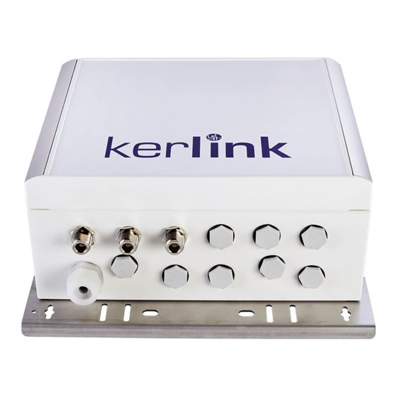
Page 23: Figure 2: Wirnet Ibts External View
(CPU, power + GPS) WAN Module (LTE) LoRa Modules (x3) Figure 3: Wirnet iBTS internal view This document is the strict property of Kerlink and shall not be either copied nor sent without express Classification written authorization of Kerlink Internal Use... -
Page 24: Poe Injector
PoE injectors Surge protections The full list of accessories is detailed in §1.8 and §6. This document is the strict property of Kerlink and shall not be either copied nor sent without express Classification written authorization of Kerlink... - Page 25 1.2.1 Standard casing The Wirnet iBTS station is built on a robust IP66 aluminum enclosure of 280 x 250 x 120 mm. It is composed of two separated parts: the frame and a lid. The lid tightens to the frame trough M5 screws, hidden by two plastic clip-on design covers.
-
Page 26: Figure 5: Enclosure Internal View
3 x N-SMB adapters (extension to 11 max) 8 x M16 blind stops (provisions for N-SMB or cable gland) This document is the strict property of Kerlink and shall not be either copied nor sent without express Classification written authorization of Kerlink... -
Page 27: Figure 6: Insertion Of The Modules Inside The Enclosure
SMB-SMB cables are provided to interconnect the RF interfaces of the modules to the SMB- N adapters, on the bottom side of the enclosure. This document is the strict property of Kerlink and shall not be either copied nor sent without express Classification... -
Page 28: Figure 7: Insertion Of The Modules Inside The Enclosure
(FCC, IC, ANATEL, etc …). The placement of the stickers is described on Figure 5. This document is the strict property of Kerlink and shall not be either copied nor sent without express Classification written authorization of Kerlink... -
Page 29: Figure 8: Wirnet Ibts Compact External View
1 x N-SMB adapters used as RF interfaces for LoRa antenna. The number of LoRa antenna interfaces can be extended to two. This document is the strict property of Kerlink and shall not be either copied nor sent without express Classification... -
Page 30: Figure 9 : Wirnet Ibts Compact Internal View
Sticker w/ serial number, regulatory, … Mounting kit Figure 9 : Wirnet iBTS Compact internal view This document is the strict property of Kerlink and shall not be either copied nor sent without express Classification written authorization of Kerlink Internal Use... - Page 31 SMB-SMB cables are provided to interconnect the RF interfaces of the modules to the SMB- N adapters, on the bottom side of the enclosure. This document is the strict property of Kerlink and shall not be either copied nor sent without express Classification...
-
Page 32: Figure 10: Insertion Of The Modules Inside The Cabinet
GPS/Cellular combo antenna Cellular antenna Figure 11: Wirnet iBTS Compact internal antennas This document is the strict property of Kerlink and shall not be either copied nor sent without express Classification written authorization of Kerlink Internal Use Kerlink m2m technologies reserved rights Confidential Kerlink –... -
Page 33: Figure 11: Common Wirnet Ibts Block Diagram
An alternate option of power supply consists in using an auxiliary power supply (11V-55V DC) and connects it to the Euroblock connector of the CPU module. This document is the strict property of Kerlink and shall not be either copied nor sent without express Classification... - Page 34 The RF front-end board is configured to support a single antenna (16 channels) or two antennas (2x8 channels). This document is the strict property of Kerlink and shall not be either copied nor sent without express Classification written authorization of Kerlink...
-
Page 35: Figure 12: Standard Wirnet Ibts Block Diagram
The GPS (GNSS) connector, the WAN (LTE) connector and LoRa connectors are available on the bottom side of the enclosure. All antennas are external antennas. This document is the strict property of Kerlink and shall not be either copied nor sent without express Classification... -
Page 36: Figure 13: Wirnet Ibts "4 Lora Modules" Block Diagram
The GPS (GNSS) connector, the WAN (LTE) connector and LoRa connectors are available on the bottom side of the enclosure. The antennas are all external antennas. This document is the strict property of Kerlink and shall not be either copied nor sent without express Classification... -
Page 37: Figure 14: Wirnet Ibts Compact Block Diagram
The LoRa connectors are available on the bottom side of the enclosure. The LoRa antennas are external antennas. This document is the strict property of Kerlink and shall not be either copied nor sent without express Classification written authorization of Kerlink... -
Page 38: Figure 15: Wirnet Ibts Fdx Block Diagrams
The GPS (GNSS) connector, the WAN (LTE) connector and LoRa connectors are available on the bottom side of the enclosure. The antennas are all external antennas. This document is the strict property of Kerlink and shall not be either copied nor sent without express Classification... -
Page 39: Figure 16: Mechanical Description Of The Cpu Module
Dimensions 156 mm x 88 mm x 38 mm Weight 500 g This document is the strict property of Kerlink and shall not be either copied nor sent without express Classification written authorization of Kerlink Internal Use Kerlink m2m technologies reserved rights Confidential Kerlink –... - Page 40 DEBUG Green Power status DEBUG Orange Software status/ activity This document is the strict property of Kerlink and shall not be either copied nor sent without express Classification written authorization of Kerlink Internal Use Kerlink m2m technologies reserved rights Confidential Kerlink –...
-
Page 41: Figure 17: Connectors And User Interfaces Of The Cpu Module
Integrated high sensitivity GNSS module GPS L1C/A, GLONASS L1OF, BeiDou B1, QZSS L1C/A, SBAS L1C/A and Galileo E1B/C ready This document is the strict property of Kerlink and shall not be either copied nor sent without express Classification written authorization of Kerlink... -
Page 42: User Interface
35mA @ 20% load CPU + Ethernet Gbits (PoE) 43mA @ 20% load CPU + Ethernet Gbits (PoE) + Local Ethernet This document is the strict property of Kerlink and shall not be either copied nor sent without express Classification... - Page 43 156 mm x 88 mm x 38 mm Weight 500 g Ingress protection IP30 This document is the strict property of Kerlink and shall not be either copied nor sent without express Classification written authorization of Kerlink Internal Use Kerlink m2m technologies reserved rights Confidential Kerlink –...
- Page 44 Note: UFL to SMA coaxial cables are used to connect the Mini PCI Express card to the antennas. This document is the strict property of Kerlink and shall not be either copied nor sent without express Classification written authorization of Kerlink...
- Page 45 50Mbps (10MHz BW) Uplink: Band 20 (800MHz) o 50Mbps (20MHz BW) This document is the strict property of Kerlink and shall not be either copied nor sent without express Classification written authorization of Kerlink Internal Use Kerlink m2m technologies reserved rights Confidential Kerlink –...
- Page 46 3GPP Release 9 B6 (850 UMTS only) B8 (900) B9 (1800) This document is the strict property of Kerlink and shall not be either copied nor sent without express Classification written authorization of Kerlink Internal Use Kerlink m2m technologies reserved rights Confidential Kerlink –...
- Page 47 Circuit-switched data bearers up to 14.4 kbps UMTS Band 1 (2100MHz) HSPA+ rates: This document is the strict property of Kerlink and shall not be either copied nor sent without express Classification written authorization of Kerlink Internal Use Kerlink m2m technologies reserved rights Confidential Kerlink –...
- Page 48 « 3 sides » flange Figure 21: Mechanical description of the Dual WAN module This document is the strict property of Kerlink and shall not be either copied nor sent without express Classification written authorization of Kerlink Internal Use...
- Page 49 Figure 22: Connectors and user interfaces of the Dual WAN module This document is the strict property of Kerlink and shall not be either copied nor sent without express Classification written authorization of Kerlink...
- Page 50 Two radiators used as right and left side flanges A front-end lid, used as a shield for the front-end board This document is the strict property of Kerlink and shall not be either copied nor sent without express Classification...
- Page 51 A front-end board embeds the radio transmitters and receivers. Three versions are derived to support the different unlicensed bands: This document is the strict property of Kerlink and shall not be either copied nor sent without express Classification written authorization of Kerlink...
- Page 52 156 mm x 102 mm x 152 mm Total weight 1700 g Ingress protection IP30 This document is the strict property of Kerlink and shall not be either copied nor sent without express Classification written authorization of Kerlink Internal Use Kerlink m2m technologies reserved rights Confidential Kerlink –...
- Page 53 Radiators material Aluminum Other flanges and lid material Galvanized Steel This document is the strict property of Kerlink and shall not be either copied nor sent without express Classification written authorization of Kerlink Internal Use Kerlink m2m technologies reserved rights Confidential Kerlink –...
- Page 54 The LoRa SMB RF connector’s # RF1 and # RF2 are connected to the SMB/N adapters on the bottom side of the Wirnet iBTS via SMB coaxial cables. This document is the strict property of Kerlink and shall not be either copied nor sent without express Classification...
- Page 55 Figure 27: RF1 and RF2 connectors of the LoRa LOC module Note: RF1 stands for RF path 1, RF2 stands for RF path 2. This document is the strict property of Kerlink and shall not be either copied nor sent without express Classification...
- Page 56 LOC module (similar to single LoRa LOC module). Note: RF1 stands for RF path 1, RF2 stands for RF path 2. This document is the strict property of Kerlink and shall not be either copied nor sent without express Classification...
- Page 57 The positions of the RF1 and RF2 connectors are indicated on the sticker on top of the LoRa LOC module (similar to single LoRa LOC module). This document is the strict property of Kerlink and shall not be either copied nor sent without express Classification...
- Page 58 Independent automatic gain control DC offset correction, quadrature correction and digital filtering Very low LO leakage This document is the strict property of Kerlink and shall not be either copied nor sent without express Classification written authorization of Kerlink Internal Use...
- Page 59 Current drain @48V 130mA in Receive Mode (all demodulators activated) 120mA in Transmit mode@27dBm This document is the strict property of Kerlink and shall not be either copied nor sent without express Classification written authorization of Kerlink Internal Use...
- Page 60 923MHz (915-928MHz) The details of the frequency bands, channelization, out of band rejection are detailed in §1.5.4.6. This document is the strict property of Kerlink and shall not be either copied nor sent without express Classification written authorization of Kerlink...
- Page 61 The following block diagram details the architecture of the front-end board, in a four modules full-duplex configuration: This document is the strict property of Kerlink and shall not be either copied nor sent without express Classification written authorization of Kerlink...
- Page 62 A first LNA with a very low noise figure, in order to not degrade the sensitivity of the receiver. This document is the strict property of Kerlink and shall not be either copied nor sent without express Classification written authorization of Kerlink...
- Page 63 Upstream (RX Wirnet iBTS) 863MHz / 873MHz Downstream (TX Wirnet iBTS) 863MHz / 873MHz This document is the strict property of Kerlink and shall not be either copied nor sent without express Classification written authorization of Kerlink Internal Use Kerlink m2m technologies reserved rights Confidential Kerlink –...
- Page 64 (TX Wirnet iBTS) Upstream 868,9+i*0,2MHz (i= 0 à 1) (RX Wirnet iBTS) This document is the strict property of Kerlink and shall not be either copied nor sent without express Classification written authorization of Kerlink Internal Use Kerlink m2m technologies reserved rights Confidential Kerlink –...
- Page 65 For Wirnet iBTS FDx, depending on the number of simultaneous Tx, the power of each carrier must be adjusted to not overrule the max +30dBm total power. The Wirnet iBTS FDx is able to transmit 4 RF signals simultaneously at each RF antenna port. 1.5.4.8 Out of band emissions Due to the very low noise transmitter, the LoRa LOC module is able to achieve excellent out of band emissions levels in the LTE, UMTS and GSM uplink or downlink bands.
- Page 66 LoRa receiver is able to demodulate signals below the noise floor i.e. with negative SNR. This document is the strict property of Kerlink and shall not be either copied nor sent without express Classification written authorization of Kerlink...
- Page 67 The level of the blockers is noticed in the table and also the difference (in dB) with the useful LoRa signal. This document is the strict property of Kerlink and shall not be either copied nor sent without express Classification...
- Page 68 Offset SF12/125KHz +/-2MHz 100dB +/-10MHz 115dB This document is the strict property of Kerlink and shall not be either copied nor sent without express Classification written authorization of Kerlink Internal Use Kerlink m2m technologies reserved rights Confidential Kerlink – 1 rue Jacqueline Auriol – 35235 THORIGNÉ-FOUILLARD...
- Page 69 236 mm x 100 mm x 40 mm Weight 1300 g Figure 34: Dimensions of the dual duplexer This document is the strict property of Kerlink and shall not be either copied nor sent without express Classification written authorization of Kerlink Internal Use...
- Page 70 ≥60 dB@960-2000 MHz ≥60 dB@960-2000 MHz ≥50 dB@2000-3000 MHz ≥50 dB@2000-3000 MHz This document is the strict property of Kerlink and shall not be either copied nor sent without express Classification written authorization of Kerlink Internal Use Kerlink m2m technologies reserved rights Confidential Kerlink –...
- Page 71 The amplitude / frequency response of the duplexer is presented below: Figure 36: S parameters of the dual duplexer This document is the strict property of Kerlink and shall not be either copied nor sent without express Classification written authorization of Kerlink...
- Page 72 Midspan PoE injector may have to be re-dimensioned. A 60W PoE injector could be then recommended instead of a 30W PoE injector. Note 2: the power supply of the Wirnet iBTS must be a limited power source. All the PoE injectors listed below must then considered as limited power sources.
- Page 73 AC Frequency: 50 to 60 Hz Dimensions 53 mm (W) x 32.5 mm (H) x 140 mm (L) This document is the strict property of Kerlink and shall not be either copied nor sent without express Classification written authorization of Kerlink...
- Page 74 The indoor AC/DC Midspan PoE injector 30W can be provided with E/F type cable (Europe) or B type cable (USA). See §6 to order the required version. This document is the strict property of Kerlink and shall not be either copied nor sent without express Classification...
- Page 75 WEEE Electromagnetic Emission & Immunity FCC Part 15, Class B EN 55022 Class B (Emissions) This document is the strict property of Kerlink and shall not be either copied nor sent without express Classification written authorization of Kerlink Internal Use...
- Page 76 In case the PoE injector cannot be installed indoor, use an alternate PoE injector dedicated to outdoor applications as detailed in §1.6.1.7. This document is the strict property of Kerlink and shall not be either copied nor sent without express Classification...
- Page 77 Note 1: beware of the operating ambient temperature. Output power derating over +50°C is critical and has to be carefully considered to insure proper supply of the Wirnet iBTS. This document is the strict property of Kerlink and shall not be either copied nor sent without express Classification...
- Page 78 DC Input Current: 2A Dimensions 87 mm (W) x 43 mm (H) x 166 mm (L) This document is the strict property of Kerlink and shall not be either copied nor sent without express Classification written authorization of Kerlink Internal Use...
- Page 79 If the electrical installation does not meet those requirements, use an alternate PoE injector featuring better surge protection as detailed in §1.6.1.7. This document is the strict property of Kerlink and shall not be either copied nor sent without express Classification...
- Page 80 ITU-T K.20 6 kV on AC lines Safety Approvals UL 60950-1, UL 60950-22 GS Mark This document is the strict property of Kerlink and shall not be either copied nor sent without express Classification written authorization of Kerlink Internal Use...
- Page 81 Dimensions 170 mm x 140 mm x 60 mm Weight 1400g This document is the strict property of Kerlink and shall not be either copied nor sent without express Classification written authorization of Kerlink Internal Use Kerlink m2m technologies reserved rights Confidential Kerlink –...
- Page 82 The following figure details the outdoor AC/DC Midspan PoE injector 60W: Figure 43 : Outdoor 60W AC/DC POE injector This document is the strict property of Kerlink and shall not be either copied nor sent without express Classification written authorization of Kerlink...
- Page 83 GR-1089-CORE Issue 4 Safety Approvals UL 60950-1, UL 60950-22 GS Mark This document is the strict property of Kerlink and shall not be either copied nor sent without express Classification written authorization of Kerlink Internal Use Kerlink m2m technologies reserved rights Confidential Kerlink –...
- Page 84 1. 1.6.2 Auxiliary power supply The Wirnet iBTS can be also supplied with an auxiliary DC power supply as a solar panel for instance. The input voltage range is 11 to 56VDC. A 24V DC solar system is then recommended for optimized performance.
- Page 85 On: Logic High (3.5-12 V) or open circuit Off: Logic Low (<1.2 V) or short pin 1 to pin 2 This document is the strict property of Kerlink and shall not be either copied nor sent without express Classification written authorization of Kerlink...
- Page 86 Note 2: beware of the operating ambient temperature. Output power derating over +60°C is critical and has to be carefully considered to insure proper supply of the Wirnet iBTS Compact. This document is the strict property of Kerlink and shall not be either copied nor sent without express Classification written authorization of Kerlink...
- Page 87 Wirnet iBTS FDx 720Wh max Note: the power supply of the Wirnet iBTS must be a limited power source. This document is the strict property of Kerlink and shall not be either copied nor sent without express Classification written authorization of Kerlink...
- Page 88 The radiation patterns are presented here after. They are measured at 870MHz (red), 868MHz (green) and 866MHz (blue): Figure 47 : Radiation pattern of omnidirectional 868MHz/3dBi antenna This document is the strict property of Kerlink and shall not be either copied nor sent without express Classification written authorization of Kerlink...
- Page 89 Note: this antenna can not be installed on the universal antenna bracket but is provided with its own mounting kit. This document is the strict property of Kerlink and shall not be either copied nor sent without express Classification written authorization of Kerlink...
- Page 90 The radiation patterns are presented here after. They are measured at 930MHz (red), 915MHz (green) and 900MHz (blue): Figure 49 : Radiation pattern of omnidirectional 915MHz/3dBi antenna This document is the strict property of Kerlink and shall not be either copied nor sent without express Classification written authorization of Kerlink...
- Page 91 The second one cannot be installed on the universal antenna bracket. This document is the strict property of Kerlink and shall not be either copied nor sent without express Classification written authorization of Kerlink...
- Page 92 The Wirnet iBTS Compact embeds a GNSS/LTE internal antenna detailed in §1.8.2.3 and therefore does not require the LTE antenna. This document is the strict property of Kerlink and shall not be either copied nor sent without express Classification written authorization of Kerlink...
- Page 93 Vertical Radiation pattern Omnidirectional Type No ground plane required This document is the strict property of Kerlink and shall not be either copied nor sent without express Classification written authorization of Kerlink Internal Use Kerlink m2m technologies reserved rights Confidential Kerlink –...
- Page 94 Note: the internal LTE antenna is directly mounted (screwed) on the SMA female connector of the Dual WAN module. This document is the strict property of Kerlink and shall not be either copied nor sent without express Classification written authorization of Kerlink...
- Page 95 The dimensions of the 865-867MHz cavity filter are detailed hereafter: Figure 51 : Dimensions of the 865-867MHz cavity filter This document is the strict property of Kerlink and shall not be either copied nor sent without express Classification written authorization of Kerlink...
- Page 96 Weight <650g Dimensions (w/o N connectors) 100 x 100 x 49 mm This document is the strict property of Kerlink and shall not be either copied nor sent without express Classification written authorization of Kerlink Internal Use Kerlink m2m technologies reserved rights Confidential Kerlink –...
- Page 97 The frequency response of 865-870MHz cavity filter is as follows: Figure 54 : Frequency response of the 865-870MHz cavity filter This document is the strict property of Kerlink and shall not be either copied nor sent without express Classification written authorization of Kerlink...
- Page 98 Figure 55 : Dimensions of the 863-873MHz cavity filter The frequency response of 863-873MHz cavity filter is as follows: This document is the strict property of Kerlink and shall not be either copied nor sent without express Classification written authorization of Kerlink...
- Page 99 Temperature range -30°C / +60°C Ports In N male / Out N female This document is the strict property of Kerlink and shall not be either copied nor sent without express Classification written authorization of Kerlink Internal Use Kerlink m2m technologies reserved rights Confidential Kerlink –...
- Page 100 The frequency response of 915-920MHz cavity filter is as follows: Figure 58 : Frequency response of the 915-920MHz cavity filter This document is the strict property of Kerlink and shall not be either copied nor sent without express Classification written authorization of Kerlink...
- Page 101 The dimensions of the 918-923MHz cavity filter are detailed hereafter: Figure 59 : Dimensions of the 918-923MHz cavity filter This document is the strict property of Kerlink and shall not be either copied nor sent without express Classification written authorization of Kerlink...
- Page 102 Power Handling ≤10W Temperature -30°C to+60°C Connectors N-Female / N-Male This document is the strict property of Kerlink and shall not be either copied nor sent without express Classification written authorization of Kerlink Internal Use Kerlink m2m technologies reserved rights Confidential Kerlink –...
- Page 103 The frequency response of 862-867MHz cavity filter is as follows: Figure 62 : Frequency response of the 920-925MHz cavity filter This document is the strict property of Kerlink and shall not be either copied nor sent without express Classification written authorization of Kerlink...
- Page 104 Figure 63 : Dimensions of the 920-928MHz cavity filter The frequency response of 920-928MHz cavity filter is as follows: This document is the strict property of Kerlink and shall not be either copied nor sent without express Classification written authorization of Kerlink...
- Page 105 Impedance 50 ohms Power Handling ≤10W Temperature -40°C to+85°C This document is the strict property of Kerlink and shall not be either copied nor sent without express Classification written authorization of Kerlink Internal Use Kerlink m2m technologies reserved rights Confidential Kerlink –...
- Page 106 Figure 65 : Dimensions of the 902-928MHz cavity filter The frequency response of 902-928MHz cavity filter is as follows: This document is the strict property of Kerlink and shall not be either copied nor sent without express Classification written authorization of Kerlink...
- Page 107 Deporting the LTE antenna may be required to optimize the LTE reception or improve isolation with other radio equipment’s on the site. Extension coaxial cables are not provided by KERLINK. This document is the strict property of Kerlink and shall not be either copied nor sent without express Classification written authorization of Kerlink...
- Page 108 GNSS antenna, LTE antenna) Earthing of the RF coaxial surge protection 16mm , copper This document is the strict property of Kerlink and shall not be either copied nor sent without express Classification written authorization of Kerlink Internal Use Kerlink m2m technologies reserved rights Confidential Kerlink –...
- Page 109 Protections must be installed in accordance to its own specifications. The following picture describes the RF coaxial surge protection: This document is the strict property of Kerlink and shall not be either copied nor sent without express Classification written authorization of Kerlink...
- Page 110 The following schematic shows electrical connections of the unipolar DC surge protection to the Wirnet iBTS and the isolated DC/DC converter: This document is the strict property of Kerlink and shall not be either copied nor sent without express Classification...
- Page 111 Main grounding wire (1.5 sq. mm) Figure 72 : Example of DC surge protection cabling This document is the strict property of Kerlink and shall not be either copied nor sent without express Classification written authorization of Kerlink Internal Use...
- Page 112 Figure 73 : Tongue terminal Wing nuts (x2) Tongue terminals (x2) Figure 74 : Tongue terminal assembly This document is the strict property of Kerlink and shall not be either copied nor sent without express Classification written authorization of Kerlink Internal Use...
- Page 113 (< 50 cm, 4 sq. mm). The principles of cablig remain identical to those described in §1.8.5.2. This document is the strict property of Kerlink and shall not be either copied nor sent without express Classification written authorization of Kerlink...
- Page 114 30 x 30 x 190 mm Weight 270g Protection rating IP66 Outdoor application This document is the strict property of Kerlink and shall not be either copied nor sent without express Classification written authorization of Kerlink Internal Use Kerlink m2m technologies reserved rights Confidential Kerlink –...
- Page 115 Note: the PoE surge protector must be connected to the earth. No cables are provided by KERLINK for that purpose. See §1.8.4.2 for additional information. This document is the strict property of Kerlink and shall not be either copied nor sent without express Classification...
- Page 116 915MHz, 3dBi omnidirectional (see §1.8.1.3). 915MHz, 6dBi omnidirectional, except FT-RF antenna (see §1.8.1.4). The universal antenna bracket is presented hereafter: This document is the strict property of Kerlink and shall not be either copied nor sent without express Classification written authorization of Kerlink...
- Page 117 LTE antenna (see §1.8.2.2) GNSS/LTE combo antenna (see §1.8.2.3) The dome antenna bracket is presented hereafter: This document is the strict property of Kerlink and shall not be either copied nor sent without express Classification written authorization of Kerlink Internal Use...
- Page 118 Note 3: the notched V shaped plate and a U-bolt can be provided by KERLINK as accessories (see §1.8.6.1). This document is the strict property of Kerlink and shall not be either copied nor sent without express Classification written authorization of Kerlink...
- Page 119 The USB cable must be connected to a computer where must be installed HyperTerminal or Teraterm to visualize the traces. This document is the strict property of Kerlink and shall not be either copied nor sent without express Classification written authorization of Kerlink...
- Page 120 USB2.0 A B cable Ethernet cable Figure 82 : WIRMA2 Debug Tool connected to the CPU module This document is the strict property of Kerlink and shall not be either copied nor sent without express Classification written authorization of Kerlink...
- Page 121 Council Recommendation 1999/519/EC: The power supply of the Wirnet iBTS 868 must be a limited power source. The Wirnet iBTS 868 is considered as a category 1.5 receiver according to the EN 300 220-1. The Wirnet iBTS 868 has CE marking.
- Page 122 SANS 60950‐1: Information technology equipment ‐ Safety Part 1: General requirements In South-Africa, the Wirnet iBTS 868 can be used with the following limitations: This document is the strict property of Kerlink and shall not be either copied nor sent without express Classification written authorization of Kerlink...
- Page 123 The Wirnet iBTS 868 is compliant to: TS031 – Non Specific Short range Devices TS001 – EMC and Safety Requirements This document is the strict property of Kerlink and shall not be either copied nor sent without express Classification written authorization of Kerlink...
- Page 124 The power supply of the Wirnet iBTS 915 must be a limited power source. The Wirnet iBTS 915 is also compliant to CFR 47 FCC Part 15 regulations: This document is the strict property of Kerlink and shall not be either copied nor sent without express Classification...
- Page 125 This equipment complies with FCC’s radiation exposure limits set forth for an uncontrolled environment under the following conditions: This document is the strict property of Kerlink and shall not be either copied nor sent without express Classification written authorization of Kerlink...
- Page 126 2. l'utilisateur de l'appareil doit accepter tout brouillage radioélectrique subi, même si le brouillage est susceptible d'en compromettre le fonctionnement. This document is the strict property of Kerlink and shall not be either copied nor sent without express Classification written authorization of Kerlink...
- Page 127 40% to not overrule the 2.784 W/m2 RF Field Strength Limits for Devices. The duty cycle, in normal conditions, is far below this limit. Do not operate the Wirnet iBTS 915 out of the 40% duty cycle limit.
- Page 128 CENELEC EN 60 950-1 (Ed. 2006/A11 : 2009/A1 : 2010/A12:2011/A2:2013) AS/NZS 60950.1 : 2011 GB4943-2011 K60950-1 J60950-1 This document is the strict property of Kerlink and shall not be either copied nor sent without express Classification written authorization of Kerlink Internal Use Kerlink m2m technologies reserved rights Confidential Kerlink –...
- Page 129 AS/NZS 4268: 2017: Radio equipment and systems – Short range devices – Limits and methods of measurement This document is the strict property of Kerlink and shall not be either copied nor sent without express Classification written authorization of Kerlink...
- Page 130 The frequency channels arrangement must be compliant to the LoRaWAN specification and the regional parameters (AU 915-928MHz) as defined in [1] and [2]. This document is the strict property of Kerlink and shall not be either copied nor sent without express Classification...
- Page 131 LoRa receiver due to co-located EGSM900 base stations. This cavity filter is described in §1.8.3.6. This document is the strict property of Kerlink and shall not be either copied nor sent without express Classification written authorization of Kerlink...
- Page 132 Measurements of the high-frequency output of radio wave application equipment and antenna power calculation methods (RRA Announce 2012-30, Dec 28, 2012) This document is the strict property of Kerlink and shall not be either copied nor sent without express Classification...
- Page 133 New Zealand labelling requirements, provided the product is declared, labelled and supplied in accordance with the Radiocommunications (Compliance Labelling) Notice 2003, This document is the strict property of Kerlink and shall not be either copied nor sent without express Classification...
- Page 134 Upstream channels 64 channels 915.2 MHz to 927.8 MHz Steps of 200 kHz This document is the strict property of Kerlink and shall not be either copied nor sent without express Classification written authorization of Kerlink Internal Use Kerlink m2m technologies reserved rights Confidential Kerlink –...
- Page 135 In Singapore, the Wirnet iBTS 923 can be used with the following limitations: Item Specification Frequency range 920-925MHz This document is the strict property of Kerlink and shall not be either copied nor sent without express Classification written authorization of Kerlink Internal Use Kerlink m2m technologies reserved rights Confidential Kerlink –...
- Page 136 In Japan, the Wirnet iBTS 923 can be used with the following limitations: Item Specification Frequency range 920.5-928.0MHz This document is the strict property of Kerlink and shall not be either copied nor sent without express Classification written authorization of Kerlink Internal Use Kerlink m2m technologies reserved rights Confidential Kerlink –...
- Page 137 Upstream and downstream channels are in orange: 38 channels, 200KHz spacing, 125KHz BW Upstream channels in medium orange: This document is the strict property of Kerlink and shall not be either copied nor sent without express Classification written authorization of Kerlink Internal Use...
- Page 138 The channels allocation can be organized differently if needed. 2.3.8 Taiwan -NCC Certification required- In Taiwan, the Wirnet iBTS 923 can be used be used as a « digitally modulated techniques systems” according to item 1, chapter 4.8.1 of the “Low Power 0002 (LP0002)” specifications.
- Page 139 Max conducted power with 3dBi antenna 250mW (24dBm) Max conducted power with 6dBi antenna 125mW (21dBm) This document is the strict property of Kerlink and shall not be either copied nor sent without express Classification written authorization of Kerlink Internal Use...
- Page 140 TISI 1956-2548 : Information Technology Equipment – Radio Disturbance Limits NTC TS 4001-2550: Electrical Safety of Telecom Terminal Equipment This document is the strict property of Kerlink and shall not be either copied nor sent without express Classification written authorization of Kerlink...
- Page 141 (AS 923MHz) as defined in [1] and [2]. 2.3.11 Brazil -ANATEL Certification required- In Brazil, the Wirnet iBTS 923 can be used according to « Resolução n°680 de 27 de junho de 2017– Regulamento Sobre Equipementos de Radiocomunicaçao de radiaçao Restrita.” Item...
- Page 142 FCC ID : 2AFYS-KLK915FDX Model : WIRNET iBTS FDX Contains FCCID : N7NMC7355 Model : MC7355 This document is the strict property of Kerlink and shall not be either copied nor sent without express Classification written authorization of Kerlink Internal Use...
- Page 143 IC : 20637-KLK915FDX Model : WIRNET iBTS FDX Contains / Contient IC : 2417C-MC7355 Model : MC7355 This document is the strict property of Kerlink and shall not be either copied nor sent without express Classification written authorization of Kerlink Internal Use...
- Page 144 40% to not overrule the 2.784 W/m2 RF Field Strength Limits for Devices. The duty cycle, in normal conditions, is far below this limit. Do not operate the Wirnet iBTS Full- Duplex out of the 40% duty cycle limit.
- Page 145 3.1 Height of the site A key factor to have an optimized Wirnet iBTS reception is the height of installation site and moreover the height of the LoRa antenna. The Wirnet iBTS gateway must be installed as high as possible to have the better reception and wider coverage area.
- Page 146 The frequency is 868MHz in this case but performance and conclusions at 915MHz would be almost identical. The RSSI is the received signal by the Wirnet iBTS. The end point EIRP is assumed to be 25mW. The height of the end point is 1m.
- Page 147 Figure 87 : Hata propagation model vs area configuration (Height = 30m) – RSSI (dBm) vs distance (m) The coverage radius of the Wirnet iBTS, depending on the area type can vary from 2 km (urban areas, low height of the LoRa antenna), up to 40 km (countryside, very high sites).
- Page 148 A global rule is that 60% of the Fresnel ellipsoid must be clear of obstacles. In case of buildings between the end point and the Wirnet iBTS, the antenna height must be adjusted to make sure the building is not close to 60% of r1.
- Page 149 Example: An end point is located at 3500m from the Wirnet iBTS. The Wirnet iBTS is installed on the roof of a building. The building roof is 30 meters long vs 20m large. What is the required height of the LoRa antenna for have an optimized reception? Answer: If we want to receive end points i.e.
- Page 150 BTS antenna have about 10 to 15dB antenna maximum gain but the gain above or below the antenna is reduced by 20dB to 30dB as described below: This document is the strict property of Kerlink and shall not be either copied nor sent without express Classification...
- Page 151 In case of sectorial antenna, the antenna gain above or below the antenna is also significantly reduced to -10 to -15dB as shown below: This document is the strict property of Kerlink and shall not be either copied nor sent without express Classification...
- Page 152 863MHz. Insuring -80dBm/100KHz at 862MHz while transmitting at 863MHz or even at 868MHz is not achievable with the state of the art of SAW filters. Therefore, the Wirnet iBTS gateway embeds specific SAW filters allowing the transmitter (LoRa-LOC module) to achieve the -80dBm/100KHz spurious limit in the LTE 800 band.
- Page 153 In Singapore, Indonesia and Hong-Kong, co-localization with EGSM900 requires usage of a specific cavity filter. See §1.8.3.6. Contact KERLINK for more information. This document is the strict property of Kerlink and shall not be either copied nor sent without express Classification...
- Page 154 In New-Zealand co-localization with GSM900 may require usage of a specific cavity filter in harsh environments (see §1.8.3.7). Contact KERLINK for more information. This document is the strict property of Kerlink and shall not be either copied nor sent without express Classification...
- Page 155 The 4 x M5 screws are now accessible. Unlock the screw with a big flat-blade screw driver (65-098 5,5x100 Stanley for instance). This document is the strict property of Kerlink and shall not be either copied nor sent without express Classification...
- Page 156 Due to the 2 hinges, there are then two open points that are noted as "A" and “B” on the picture below: This document is the strict property of Kerlink and shall not be either copied nor sent without express Classification...
- Page 157 (like to drive screws into the slot). Here you have to use more strength because the lever arm is smaller. This document is the strict property of Kerlink and shall not be either copied nor sent without express Classification...
- Page 158 LIFT UP HINGE OPENED Figure 97 : Opening of the compact enclosure with screwdriver This document is the strict property of Kerlink and shall not be either copied nor sent without express Classification written authorization of Kerlink Internal Use Kerlink m2m technologies reserved rights Confidential Kerlink –...
- Page 159 Without USIM Subscription: Figure 98 : Single station installation (with USIM) Figure 99 : Single station installation (No USIM) This document is the strict property of Kerlink and shall not be either copied nor sent without express Classification written authorization of Kerlink...
- Page 160 Figure 100 : Multi-station installation (No USIM) Note 2: this configuration is no longer detailed in the present document This document is the strict property of Kerlink and shall not be either copied nor sent without express Classification written authorization of Kerlink...
- Page 161 RF coaxial cables and earthing connections. Figure 101 : Power distribution in the installation This document is the strict property of Kerlink and shall not be either copied nor sent without express Classification written authorization of Kerlink...
- Page 162 The installation of the PoE cable is detailed in §4.6.3. 4.3.4 Auxiliary power supply The Wirnet iBTS can be also supplied with an auxiliary DC power supply as a solar panel for instance. The input voltage range is 11 to 56VDC. A 24V DC solar system is then recommended for optimized performance.
- Page 163 Screw the module on the blind threaded standoffs with the provided M4 screws This document is the strict property of Kerlink and shall not be either copied nor sent without express Classification written authorization of Kerlink...
- Page 164 Screw the N-SMB adapter on the bottom side of the enclosure with M19 wrench (3Nm tightening torque) This document is the strict property of Kerlink and shall not be either copied nor sent without express Classification written authorization of Kerlink...
- Page 165 Connect the SMB-SMB coaxial cable between the N-SMB adapter and the RF1 (and RF2) port of the LoRa module This document is the strict property of Kerlink and shall not be either copied nor sent without express Classification written authorization of Kerlink...
- Page 166 The antenna is provided with a 5m coaxial cable. Extension coaxial cables of could be used to reach a better position but are not provided by KERLINK. However, beware of the insertion losses! This document is the strict property of Kerlink and shall not be either copied nor sent without express Classification written authorization of Kerlink...
- Page 167 Figure 102 : Position of the universal antenna support when mounted on the compact enclosure support This document is the strict property of Kerlink and shall not be either copied nor sent without express Classification written authorization of Kerlink...
- Page 168 (as follow) to have a better isolation between the LoRa antenna and the GPS/LTE internal antennas. This document is the strict property of Kerlink and shall not be either copied nor sent without express Classification written authorization of Kerlink...
- Page 169 Figure 104 : Pole mounting of the universal antenna bracket using strapping 2 x M8 bolts+ nuts Figure 105 : Universal antenna bracket with compact casing mounting kit This document is the strict property of Kerlink and shall not be either copied nor sent without express Classification written authorization of Kerlink...
- Page 170 On a pole: alternate option is to use the “notched V shaped plate and a U-bolt” as detailed in §1.8.6.1. The maximum diameter of the pole is 60mm. This document is the strict property of Kerlink and shall not be either copied nor sent without express Classification...
- Page 171 Figure 107 : N connector introduced in the hole of the dome antenna bracket Gasket M22 nut Figure 108 : Antenna installed on the dome antenna bracket This document is the strict property of Kerlink and shall not be either copied nor sent without express Classification written authorization of Kerlink Internal Use...
- Page 172 2 x M4 screws 2 x M4 screws Figure 110 : Compact casing - Wall mount This document is the strict property of Kerlink and shall not be either copied nor sent without express Classification written authorization of Kerlink Internal Use...
- Page 173 M8 bolt and nut (see §4.6.1.2). 4.5.3.3 Pole mounting by U-bolt The Wirnet iBTS is delivered with a U-bolt to be mounted on a pole with a maximum diameter of 60mm. To screw the U-bolt, it is recommended to use the nuts provided in the mounting kit.
- Page 174 4.5.4.1 Standard casing mounting kit The standard casing mounting kit is composed of two identical parts as shown below: This document is the strict property of Kerlink and shall not be either copied nor sent without express Classification written authorization of Kerlink...
- Page 175 The Wirnet iBTS is delivered with the standard casing mounting kit already installed on the rear side: Figure 115 : Rear view of the standard casing with mounting kit This document is the strict property of Kerlink and shall not be either copied nor sent without express Classification written authorization of Kerlink...
- Page 176 U-bolts 1 nut on each side Figure 117 : Standard casing - Pole mount using U-bolts This document is the strict property of Kerlink and shall not be either copied nor sent without express Classification written authorization of Kerlink Internal Use...
- Page 177 Alternate Strapping positions Figure 119 : Standard casing - Pole mount using strapping This document is the strict property of Kerlink and shall not be either copied nor sent without express Classification written authorization of Kerlink Internal Use Kerlink m2m technologies reserved rights Confidential Kerlink –...
- Page 178 (positions 1, 2 and 3 below): 3 x M3 screws Figure 121 : Screws for outdoor POE injectors mounting This document is the strict property of Kerlink and shall not be either copied nor sent without express Classification written authorization of Kerlink...
- Page 179 The outdoor Ethernet surge protection is provided with an “omega” bracket dedicated to wall mounting. Use 2 x M4 screws to fix to bracket on the wall: This document is the strict property of Kerlink and shall not be either copied nor sent without express Classification...
- Page 180 Mount the surge protection on the pole and use a metallic strapping or worm gear clam to fix it: Figure 125 : Outdoor Ethernet Surge protection – pole mounting with strapping This document is the strict property of Kerlink and shall not be either copied nor sent without express Classification written authorization of Kerlink...
- Page 181 Some of them can also be wall mounted with 4 x M4 x 8 mm screws as detailed in Figure 51 and Figure 61. This document is the strict property of Kerlink and shall not be either copied nor sent without express Classification...
- Page 182 The earthing cables characteristics are detailed in §1.8.4.2. Note: the earthing cables are not provided by KERLINK. This document is the strict property of Kerlink and shall not be either copied nor sent without express Classification written authorization of Kerlink...
- Page 183 Note 2: the earthing cable characteristics are detailed in §1.8.4.2. Note 3: use a crimping tool to crimp the ring tongue terminal with earthing cable. This document is the strict property of Kerlink and shall not be either copied nor sent without express Classification...
- Page 184 Crimp the ring tongue terminal to earthing cable with the crimping tool Connect the ring tongue to the mounting kit with M8 bolt (or U-bolt) and nut. This document is the strict property of Kerlink and shall not be either copied nor sent without express Classification...
- Page 185 The other side of the cable could be connected theough a ring tongue terminal. An example of cabling is described on §1.8.5.2. This document is the strict property of Kerlink and shall not be either copied nor sent without express Classification...
- Page 186 The earthing connection is completed through a ring terminal. The earthing cable must be crimped inside this ring terminal. This document is the strict property of Kerlink and shall not be either copied nor sent without express Classification...
- Page 187 Note 1: the earthing cables are not provided by KERLINK Note 2: the earthing cables characteristics are detailed in §1.8.4.2. This document is the strict property of Kerlink and shall not be either copied nor sent without express Classification written authorization of Kerlink...
- Page 188 Figure 136 : nominal configuration of N connectors - standard casing Therefore, in its nominal configuration, only one N connector is available for a single antenna. This document is the strict property of Kerlink and shall not be either copied nor sent without express Classification written authorization of Kerlink...
- Page 189 In its default configuration, the compact casing features only one N-SMB adapters used as RF interfaces for the LoRa antenna: This document is the strict property of Kerlink and shall not be either copied nor sent without express Classification written authorization of Kerlink...
- Page 190 If antenna diversity is required then the installer has to mount an additional N-SMB adapter on the bottom side of the enclosure. The M16 blind stop is available for that purpose. This document is the strict property of Kerlink and shall not be either copied nor sent without express Classification...
- Page 191 Figure 139 : GNSS antenna cabling, internal and external Make sure the SMA-SMB cable inside the enclosure is properly connected to the CPU module. This document is the strict property of Kerlink and shall not be either copied nor sent without express Classification written authorization of Kerlink...
- Page 192 Check the antenna is well mounted on the bracket and the SMA connectors are properly screwed on the modules, as described below: This document is the strict property of Kerlink and shall not be either copied nor sent without express Classification...
- Page 193 (oriented to bottom side of the enclosure) Figure 142 :Internal LTE antenna within Wirnet iBTS Compact This document is the strict property of Kerlink and shall not be either copied nor sent without express Classification written authorization of Kerlink Internal Use...
- Page 194 To tighten the coaxial cable of the Wirnet iBTS Compact, the installer can use cable clamps inserted in the dedicated slots of the mounting kit: This document is the strict property of Kerlink and shall not be either copied nor sent without express Classification...
- Page 195 In this configuration, the Wirnet iBTS receiver supports 16 channels. Figure 145 : Single LoRa module / single omnidirectional antenna connections This document is the strict property of Kerlink and shall not be either copied nor sent without express Classification...
- Page 196 In this configuration, the Wirnet iBTS receiver supports 2 x 8 channels. Figure 147 : Single LoRa module / single dual polarization antenna connections This document is the strict property of Kerlink and shall not be either copied nor sent without express Classification...
- Page 197 In this configuration, the Wirnet iBTS receiver supports 2 x 2 x 8 channels. Figure 149 : Two LoRa modules / two dual polarization antennas connections This document is the strict property of Kerlink and shall not be either copied nor sent without express Classification...
- Page 198 In this configuration, the Wirnet iBTS receiver supports 3 x 2 x 8 channels. Figure 151 : Three LoRa modules / three sectors antennas / dual polarization connections This document is the strict property of Kerlink and shall not be either copied nor sent without express Classification...
- Page 199 In this configuration, the Wirnet iBTS receiver supports 2 x 32 channels. Figure 153 : Four LoRa modules / dual omnidirectional antennas / diversity connections This document is the strict property of Kerlink and shall not be either copied nor sent without express Classification...
- Page 200 Connect the RJ45 connector in to the PoE/LAN port of the CPU module Replace the seal in the cable gland body Screw the external nut This document is the strict property of Kerlink and shall not be either copied nor sent without express Classification written authorization of Kerlink...
- Page 201 CPU module M25 cable gland RJ45 cable Figure 156 : Ethernet connection on Wirnet iBTS side This document is the strict property of Kerlink and shall not be either copied nor sent without express Classification written authorization of Kerlink Internal Use...
- Page 202 USIM card inserted (see §4.7). 4.6.5 Auxiliary power supply The Wirnet iBTS can be also supplied with an auxiliary DC power supply as a solar panel for instance. The input voltage range is 11 to 56VDC. A 24V DC solar system is then recommended for optimized performance.
- Page 203 USIM card inserted (see §4.7). Note 3: the external power supply must be a limited power source. This document is the strict property of Kerlink and shall not be either copied nor sent without express Classification...
- Page 204 The following figure describes the lighting protections that are required in a high keraunic area configuration: Figure 159 : Installation with recommended lighting protections This document is the strict property of Kerlink and shall not be either copied nor sent without express Classification written authorization of Kerlink...
- Page 205 In this use case, the installation is still composed of two separated areas: indoor installation and outdoor installation. This document is the strict property of Kerlink and shall not be either copied nor sent without express Classification written authorization of Kerlink...
- Page 206 Figure 160 : Installation with recommended lighting protections / Outdoor PoE injector This document is the strict property of Kerlink and shall not be either copied nor sent without express Classification written authorization of Kerlink...
- Page 207 Insert and press the USIM card here Figure 161 : USIM Card This document is the strict property of Kerlink and shall not be either copied nor sent without express Classification written authorization of Kerlink Internal Use Kerlink m2m technologies reserved rights Confidential Kerlink –...
- Page 208 Wirnet iBTS can be powered ON. To POWER ON the Wirnet iBTS, connect the POE injector onto the 230VAC mains supply. 4.8.3 Functional check To ensure the Wirnet iBTS is started up, check the behavior of the LED indicators on the CPU module: Connector...
-
Page 209: Configuring Network Parameters
IPv4 Gateway address & network mask o IPv4 DNS resolver GSM / HSPA / LTE: This document is the strict property of Kerlink and shall not be either copied nor sent without express Classification written authorization of Kerlink... -
Page 210: Configuring Credentials
Change the root, usbuser and support passwords (through commande-line only) Consult the Kerlink Wiki or contact KERLINK for more information. This document is the strict property of Kerlink and shall not be either copied nor sent without express Classification... -
Page 211: Maintenance Of The Wirnet Ibts
Wirnet iBTS + mounting kit earthing cable is connected and not deteriorated. Surge protectors earthing cables are connected and not deteriorated. This document is the strict property of Kerlink and shall not be either copied nor sent without express Classification... -
Page 212: Adding Or Replacing A Module
The connections of the Wirma2 Debug Tool to the CPU module and the computer are detailed on the following picture: This document is the strict property of Kerlink and shall not be either copied nor sent without express Classification written authorization of Kerlink... - Page 213 Use HyperTerminal or Teraterm on the computer to visualize the traces. The serial port must be configured as follows: Figure 163 : Serial port configuration This document is the strict property of Kerlink and shall not be either copied nor sent without express Classification written authorization of Kerlink...
-
Page 214: Usb Interface
This button is intended to perform a hard reboot, soft halt, power down (hard halt)and power on of the Wirnet iBTS: This document is the strict property of Kerlink and shall not be either copied nor sent without express Classification... -
Page 215: Local Interface
Press the button once (<1s)to complete the hard reboot of the Wirnet iBTS Press the button during 1s to 5s to perform a soft halt. The Wirnet iBTS closes the SW applications and reboots within the next 2minutes. -
Page 216: List Of The Accessories
Quad LoRa Modules 923 – LoRa LOC – 64 channels, including: 2 X N-SMB adapter 2 x RF coaxial SMB/SMB cable This document is the strict property of Kerlink and shall not be either copied nor sent without express Classification written authorization of Kerlink... - Page 217 2 X LTE Europe / APAC Mini PCI Express module MC7304 2 X N-SMB adapter 2 x RF coaxial SMB/SMA cable 1 x backup battery This document is the strict property of Kerlink and shall not be either copied nor sent without express Classification written authorization of Kerlink Internal Use...
- Page 218 Cables: KERLINK Reference Designation ACCIOT-CAB00 RF coaxial cable N-N 1m This document is the strict property of Kerlink and shall not be either copied nor sent without express Classification written authorization of Kerlink Internal Use Kerlink m2m technologies reserved rights Confidential Kerlink –...
- Page 219 DC surge protection, 1 pole (KLK02881) KLK02880 DC surge protection, 2 poles This document is the strict property of Kerlink and shall not be either copied nor sent without express Classification written authorization of Kerlink Internal Use Kerlink m2m technologies reserved rights Confidential Kerlink –...
-
Page 220: Customer Support
If an issue is not addressed in this document, contact your first level of support. This document is the strict property of Kerlink and shall not be either copied nor sent without express Classification written authorization of Kerlink... - Page 221 Version : 2.0 Author : SNI Date : 04/12/2018 ND OF OCUMENT This document is the strict property of Kerlink and shall not be either copied nor sent without express Classification written authorization of Kerlink Internal Use Kerlink m2m technologies reserved rights Confidential Kerlink –...